
Related Manuals for H-KING DH82A TIGER MOTH


Summary of Contents for H-KING DH82A TIGER MOTH
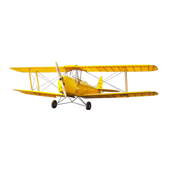
- Page 1 1:3.8 DE HAVI L LAND DH82A TIGER MOTH FULL LASER CUT BALSA KIT BUILDING INSTRUCTION...
-
Page 2: Safety Precautions
WARNING Please read this instruction manual fully and become completely familiar with the features of this product before operating. Failure to operate this product correctly could result in damage to the product, personal property and cause serious injury. This is a sophisticated hobby product and is NOT a toy. It must always be operated with caution, common sense and some basic mechanical ability. -
Page 3: Parts List
Features: • Faithfully produced flying scale model of the full size DH82A Tiger Moth • All wood state of the art lightweight construction • Includes a high quality fiberglass cowl • Includes a complete hardware pack • Includes stainless steel flying wires and metal fittings •... - Page 4 Building Sequence: A. Servo Mount Assembly. 1. Make a servo tray by laminating together parts A28, A31, A32 and their plywood doublers using epoxy glue. Hold the assemblies together using clamps as the glue sets. B. Nose Assembly. 1. Make a pair of A2 by laminating together A1 and A2 and their 2.
- Page 5 C. Fuselage Frame Assembly. 1. Make two assemblies using A25 and A26 and glue together 2. Make two side panels by glueing together the A25/A26 laminate using epoxy glue. Ensure you make a right and a left-hand side. to part A7, ensure you make a right and left-hand side. Add the pinewood strip stiffeners as shown on the plan.
- Page 6 5. When the above assembly is done, add the bottom ply sheeting 6. Then add bulkheads A8, A12, A13 and strengthening plates A37, hold in place with clamps as the glue sets. A39, use clamps to hold in place as the glue sets. 7.
- Page 7 9. Using pine wood strips, build over the plan 2 x rear fuselage assemblies, remember you are making a left and right-hand side. When done join these rear fuselage assemblies to the front fuselage assembly. Do this over the plan to ensure perfect alignment and hold with mini clamps until the glue sets.
- Page 8 11. Glue the formers to the top rear part of the fuselage, once again do this over the plan to ensure the sides pull in evenly to the rear. When the bulk- heads are in place and the glue has set, add the pine wood stringers as shown on the plan and in the picture to form the turtledeck structure. 12.
- Page 9 13. At the tail end to enable the pine wood strip to bend at the required angle you will need to make a small cut. Then join together 2 x A23 and A24, once assembled trim with a hobby knife to form the tail into the required point, glue together and hold with clamps as the glue sets. Do this over the plan to ensure the tail pulls together evenly and to the correct profile.
- Page 10 2. Trim to fit the 1mm pine wood capping strips as shown on the plan, see step 3 before fitting. 3. Make 1mm deep notches in the leading edge to accomodate the 1mm pine wood capping strips.
- Page 11 5. Bend the 4mm stainless steel tube to form the trailing edge of the elevators 4. Sand the leading edge to the section shown on the plan. according to the shape on the plan. Then drill 2 x 4mm holes for each elevator in the 10x10mm wood leading edge for the stainless steel tube to fit into.
- Page 12 E. Fin and Rudder Assembly. 1. Trim to length and sand the 8x14x300mm according to the shape on 2. Glue all the rudder ribs to the spar as shown on the plan. Add the the plan. Use a round file to form a notch on the tip to accomodate 1mm capping strips to both sides of each rib.
- Page 13 5. Assemble the ribs and cappings and spars to form the fin, see step 6. Cut 6 1mm slots (3 each side) at the tips and in the middle of the fin 6 before commencing. leading edge at the angles shown. When satisfied with the fit then glue the leading edge into place.
- Page 14 F. Upper Wing Center Section (Fuel Tank) Assembly. 1. Assemble the upper wing center section using the parts as shown. 2. Glue on the leading and trailing edges as shown, then sand to the When done sheet the assembly top and bottom with 1mm plywood. profiles shown once the glue has dried.
- Page 15 G. Upper Wing Assembly. 1. Indentify all the parts required to assemble the upper wings and construct both panels over the plan on a flat surface as shown. Pin the components down to ensure the panels stay flat as the glue sets. Note that the ribs have tabs so that they sit on the building board at the correct angle.
- Page 16 3. Use pliers to bend the metal fittings to shape, and drill holes on the wing spar as shown on the plan for the metal flying wire fittings. Use the supplied screws and nylon insert lock nuts to hold these fittings in place as shown in the sequence of pictures.
- Page 17 4. Please repeat the above sets to make the opposite side wing.
- Page 18 5. Reinforce the wing root by laminating 2 x D1 together 6. Glue to the main spar and the leading edge the half ribs which go with epoxy glue. between each of the main ribs. 7. Install an 8mm wooden dowel and the metal fittings as shown using the supplied 8.
- Page 19 9. Glue into place the wing strut mounting blocks then attach the metal fittings as shown on the plan. Thread the supplied 0.8mm diameter torsion wires through the ribs and attach them to the metal fittings inside the wing. Ensure these wires are tightened as much as possible to get the most out of the torsional strength.
- Page 20 3. Install the wing spars to the ribs. Please note that the lower 4. Use pins to hold the parts down to the plan as the glue dries to stop any wing spars are pre-shaped, the front spars are bevelled towards warping of the panels.
- Page 21 6. Shape the ends of the wing spars at the wing tip as shown, then glue into position the wing rib E9. 7. Next turn the wing over and install the 8. Use a pencil to mark the centre line of the wing 9.
- Page 22 10. Glue into place the root ribs E1. At this point install the torsional 11. Glue into place to the front spar and the leading edge the half ribs which strengthening wires as per the top wings. go between each of the main wing ribs. 12.
- Page 23 14. Glue balsa sheet to the aileron leading edge spar and sand accord- ingly. Then add the plywood capping strips 15. Install the 8mm wooden dowel as shown in the picture and on the plan. 16. Install the wing mounting metal parts with the Then screw to the trailing edge the metal flying wire fittings as shown.
- Page 24 18. Drill holes for the aileron pin hinges in the positions 17. Assemble then install the wing mounting bolts as shown on the plan, hinge the ailerons. Note: You may shown on the plan and in the pictures. wish to leave glueing the hinges until after the model has been covered.
- Page 25 J. Main landing gear assembly 1. Identify all the metal parts, screws and nuts for the assembly of the main landing gear. 2. Assemble the parts in the sequence shown, starting with the sprung oleo parts. Assemble these as shown in the picture and lock each end with the nylon insert nuts.
- Page 26 4. Join together the supporting steel tube braces as shown in the pictures and on the plan. 5. Fix the finished landing gear assembly to the fuselage. This will need to be removed when you cover the model.
-
Page 27: Cockpit Doors
K. Other Assemblies. Cockpit doors. 1. Glue the door frame ribs to the 1mm plywood sheeting 2. Add the stringers to the tops as shown. as shown, hold with clamps as the glue sets. Wing Struts. 1. Mark the profile on the inter-plane wing struts with pencil 2. -
Page 28: Rudder Servo Installation
Rudder Servo Installation. 1. Install the rudder servo and bellcrank system as shown for the external closed loop system. - Page 29 Main Wing Struts. 1. Build the assembly as shown on the plan and in the pictures. Make sure that you get the wing incidence rigging angle correct. Upper and Lower Wing Dihedral. 1. Rig the model completely and adjust the flying wires to achieve the correct dihedral angles. The top wing has a dihedral angle of 1° each side and the lower wing is 4.5°...
- Page 30 Hope you enjoyed building your H-King Tiger Moth and that you will have many pleasant flights with it.
- Page 31 List of 1:3.8 Tiger Moth Parts Item. Spec. Item. Spec. Metal Accessories Stainless steel cutting plate TM-01 M1.2 TM-21 Accessories plate Aluminum Crimp Tube TM-02 M0.8 TM-22 Accessories plate 0.8MM Steel tube for landing gear φ8mm TM-03 Needle hinge M2.6X43 TM-04 Ball stud 3XH5XL29XM3...
- Page 32 TM-28- TM-06 TM-14 TM-15- TM-31- Pictures for accessories of 1:3.8 scale Tiger Moth TM-07 TM-01- TM-19- TM-33- TM-08 TM-17 TM-10 TM-35- TM-03 TM-11 TM-21 TM-09 TM-18 TM-04 TM-12 TM-22 TM-41 TM-46 TM-51 TM-23- TM-05 TM-13 TM-42 TM-47 TM-52 TM-28- TM-06 TM-14 TM-48- TM-43...
Need help?
Do you have a question about the DH82A TIGER MOTH and is the answer not in the manual?
Questions and answers