
Subscribe to Our Youtube Channel
Related Manuals for Bailey infi 90 NIDI01


Summary of Contents for Bailey infi 90 NIDI01
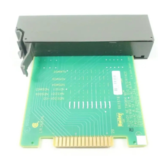
- Page 1 E96-410 ® ® Digital Input Termination Module (NIDI01) Process Control and Automation Solutions from Elsag Bailey Group...
- Page 2 The information contained in this document is subject to change without notice. Elsag Bailey, its affiliates, employees, and agents, and the authors and contributors to this publication specif- ically disclaim all liabilities and warranties, express and implied (including warranties of merchantability and...
- Page 3 Slave Output Module. • IMFCS01 Frequency Counter Slave Module. • IMHSS02 Hydraulic Servo Slave Module. • IMLMM02 Logic Master Module. This product instruction explains how to install and configure the NIDI01 termination module. ® Registered trademark of Elsag Bailey Process Automation. I-E96-410A...
- Page 4 ® List of Effective Pages Total number of pages in this manual is 46, consisting of the following: Page No. Change Date Preface Original List of Effective Pages Original iii through vii Original 1-1 through 1-5 Original 2-1 through 2-8 Original Original 4-1 through 4-2...
- Page 5 ® Safety Summary GENERAL Equipment Environment WARNINGS All components, whether in transportation, operation or storage, must be in a noncorrosive environment. Electrical Shock Hazard During Maintenance Disconnect power or take precautions to insure that contact with energized parts is avoided when servicing. SPECIFIC If input or output circuits are a shock hazard after disconnecting sys- WARNINGS...
- Page 6 Sommaire de Sécurité AVERTISSEMENTS Environment de l'equipement D’ORDRE Nes pas soumettre les composantes a une atmosphere corrosive GÉNÉRAL lors du transport, de l'entreposage ou de l'utilisation. Risques de chocs electriques lor de l'entretien S'assurer de debrancher l'alimentation ou de prende les precau- tions necessaires a eviter tout contact avec des composants sours tension lors de l'entretien.
-
Page 7: Table Of Contents
Table of Contents Page SECTION 1 - INTRODUCTION ....................1-1 OVERVIEW ........................1-1 INTENDED USER ......................1-1 INSTRUCTION CONTENT .....................1-1 HOW TO USE THIS MANUAL ..................1-2 GLOSSARY OF TERMS AND ABBREVIATIONS .............1-2 REFERENCE DOCUMENTS..................1-3 NOMENCLATURE ......................1-4 SPECIFICATIONS ......................1-4 SECTION 2 - INSTALLATION .....................2-1 INTRODUCTION......................2-1 SPECIAL HANDLING ....................2-1 UNPACKING AND INSPECTION ..................2-2... - Page 8 ® Table of Contents (continued) Page APPENDIX F - IMDSO04 DIGITAL SLAVE OUTPUT MODULE CONFIGURATION....F-1 INTRODUCTION ......................F-1 APPENDIX G - IMFCS01 FREQUENCY COUNTER SLAVE MODULE CONFIGURATION..G-1 INTRODUCTION ......................G-1 APPENDIX H - IMHSS02 HYDRAULIC SERVO SLAVE MODULE CONFIGURATION ... H-1 INTRODUCTION ......................H-1 APPENDIX I - IMLMM02 LOGIC MASTER MODULE CONFIGURATION ........I-1 INTRODUCTION ......................
- Page 9 List of Tables Title Page 1-1. Glossary of Terms and Abbreviations ..............1-3 1-2. Reference Documents ....................1-3 1-3. Nomenclature ......................1-4 1-4. Specifications......................1-4 2-1. Jumper J1 through J10 Settings ................2-3 2-2. NIDI01 Cable Applications ..................2-4 3-1. Maintenance Schedule ...................3-1 A-1. IMASO01 Switch S1 (Address Examples) ............... A-2 A-2.
-
Page 10: Section 1 - Introduction
Repair/Replacement Details how to replace an IDI module. Procedures Support Services Describes the support services (spare parts, training, docu- mentation, etc.) available from Bailey Controls Company. Appendices A through I List the quick reference information necessary to configure IMASO01, IMDSI02,... -
Page 11: How To Use This Manual
INTRODUCTION ® COMMUNICATION HIGHWAY (INFI-NET OR PLANT LOOP) COMMUNICATION MODULES CONTROLWAY OR MODULE BUS IMMFP01/02/03 IMLMM02 IMMFC03/04/05 OTHER MODULES SLAVE EXPANDER BUS IMASO01 IMDSI02 IMDSM04/05 IMDSO01/02/03/04 IMFCS01 IMHSS02 OTHER SLAVE MODULES NIDI01 NIDI01 DIGITAL I/O DIGITAL I/O T00513A Figure 1-1. Example NIDI01 Termination Module Application HOW TO USE THIS MANUAL Read this manual through in sequence. -
Page 12: Reference Documents
IMDSM05 Digital I/O Slave Module I-E96-310 IMDSO01/02/03 Digital Slave Output Module I-E96-313 IMDSO04 Digital Slave Output Module I-E96-314 IMFCS01 Frequency Counter Slave Module I-E96-315 IMHSS02 Hydraulic Servo Slave Module ® Registered trademark of Elsag Bailey Process Automation. REFERENCE DOCUMENTS I-E96-410A 1 - 3... -
Page 13: Nomenclature
INTRODUCTION ® NOMENCLATURE Table is a list of related hardware. Table 1-3. Nomenclature Nomenclature Hardware/Description NIDI01 Digital input termination module. NKTU02 Termination module cable (PVC). NKTU12 Termination module cable (non-PVC). NKTM01 Termination module cable (ribbon). NTMU01 Termination mounting unit, rear mounting. NTMU02 Termination mounting unit, front mounting. - Page 14 INTRODUCTION Table 1-4. Specifications (continued) Property Characteristic/Value Inputs and Outputs Inputs Outputs (continued) Module Analog Digital Analog Digital IMHSS02 LVDT secondary inputs servo drive outputs LVDT pri- mary drive raise, lower and trip bias signals emergency manual drive signal IMLMM02 125 VDC, 120 VAC and 24 VDC...
-
Page 15: Section 2 - Installation
SPECIAL HANDLING Observe these steps when handling electronic circuitry: NOTE: Always use Bailey's Field Static Kit (P/N 1948385A1 - con- sisting of two wrist straps, ground cord assembly, alligator clip and static dissipating work surface) when working with the modules. The... -
Page 16: Unpacking And Inspection
® UNPACKING AND INSPECTION 1. Examine the hardware immediately for shipping damage. 2. Notify the nearest Bailey Controls Company sales office of any such damage. 3. File a claim for any damage with the transportation com- pany that handled the shipment. -
Page 17: Cable Connections
INSTALLATION Table 2-1. Jumper J1 through J10 Settings Jumper Position Master/Slave Module Type IMASO01 IMDSI02/IMDSO04 IMDSM04 IMDSM05 IMDSO01/02/03 IMFCS01 IMHSS02 IMLMM02 NOTE: 0 = open or cut jumper (cut jumpers at both ends to completely remove), 1 = intact or shorted jumper. Cable Connections The NIDI01 Digital Input Termination Module terminates ana- log and digital I/O signals, and interfaces them directly to a... -
Page 18: Cable Installation
INSTALLATION ® Table 2-2. NIDI01 Cable Applications Nomenclature/ Maximum Application Connections Description Length NKTU02 PVC Connects the IDI module to the P1 of the IDI module to P3 of 61 m Termination Cable master or slave module. the master or slave module. (200 ft) NKTU12 non PVC Termination Cable... -
Page 19: Installing The Termination Module
INSTALLATION 3. Insert the J2 end (use either end of the NKTM01 cable) of the NKTU02 or NKTU12 cable into the MMU backplane slot assigned to the master or slave module. The cable should latch securely into place. Card edge connector P3 of the master or slave module connects to this end of the cable. - Page 20 INSTALLATION ® WARNING If input or output circuits are a shock hazard after disconnect- ing system power at the power entry panel, then the door of the cabinet containing these externally powered circuits must be marked with a warning stating that multiple power sources exist.
-
Page 21: Nidi01 Terminal Strip Assignments
INSTALLATION 2. All required cables are installed and verified. 3. If required, power is connected and applied to the IDI module. MODULES TERMINAL NUMBER USING NIDI01 9 10 11 12 13 14 15 16 17 18 19 20 21 22 23 24 25 26 27 28 29 30 31 32 IMDSI02 –... - Page 22 INSTALLATION ® FUSE SYSTEM POWER FIELD CONTACTS NIDI01 – – – COMMON BUS BAR IN TERMINATION MOUNTING UNIT T00517A Figure 2-4. Example System Powered Digital Input Connections – FIELD POWER FIELD CONTACTS NIDI01 – – – T00518A Figure 2-5. Example Field Powered Digital Input Connections SETUP/PHYSICAL INSTALLATION 2 - 8...
-
Page 23: Section 3 - Maintenance
SECTION 3 - MAINTENANCE INTRODUCTION The digital input termination module requires limited mainte- nance. This section contains a maintenance schedule. MAINTENANCE SCHEDULE Execute the tasks in Table at the specified intervals. Table 3-1. Maintenance Schedule Task Interval Clean and tighten all power and field wir- Every 6 months or during ing connections. -
Page 24: Section 4 - Repair/Replacement Procedures
SECTION 4 - REPAIR/REPLACEMENT PROCEDURES INTRODUCTION This section explains how to replace a failed NIDI01 Digital Input Termination Module. MODULE REPLACEMENT PROCEDURES If an IDI termination module is faulty, replace it with a new one. To replace an IDI termination module: CAUTION It is strongly recommended that all power (cabinet, I/O, etc.) be turned off before doing any termination module wiring. - Page 25 REPAIR/REPLACEMENT PROCEDURES ® 10. Apply power to the cabinet containing the replacement IDI module. MODULE REPLACEMENT PROCEDURES 4 - 2 I-E96-410A...
-
Page 26: Section 5 - Support Services
SECTION 5 - SUPPORT SERVICES INTRODUCTION Bailey Controls Company is ready to help in the use, applica- tion and repair of its products. Contact the nearest sales office to make requests for sales, applications, installation, repair, overhaul and maintenance contract services. -
Page 27: Appendix A - Imaso01 Analog Slave Output Module Configuration
APPENDIX A - IMASO01 ANALOG SLAVE OUTPUT MODULE CONFIGURATION INTRODUCTION Figure shows the location of dipswitches used to configure the IMASO01 Analog Slave Output Module (ASO). Tables give the dipswitch settings to configure the module. This information is provided as a quick reference guide for per- sonnel installing the NIDI01 termination module. - Page 28 IMASO01 ANALOG SLAVE OUTPUT MODULE CONFIGURATION ® Table A-1. IMASO01 Switch S1 (Address Examples) Switch Position (Binary Value) Address Example (128) (64) (32) (16) NOTES: 0 = CLOSED or ON, 1 = OPEN or OFF. 1. Switch positions 1 and 2 must remain CLOSED. Table A-2.
-
Page 29: Appendix B - Imdsi02 Digital Slave Input Module Configuration
APPENDIX B - IMDSI02 DIGITAL SLAVE INPUT MODULE CONFIGURATION INTRODUCTION Figure shows the location of the dipswitches and jumpers used to configure the IMDSI02 Digital Slave Input Module (DSI). Tables give the dipswitch and jumper set- tings to configure the module. This information is provided as a quick reference guide for personnel installing the NIDI01 ter- mination module. -
Page 30: Imdsi02 Digital Slave Input Module
IMDSI02 DIGITAL SLAVE INPUT MODULE CONFIGURATION ® Table B-2. IMDSI02 Jumpers J1 through J32 (Digital Input Voltage Level and DC Voltage Response Time) 24 VDC Digital Input Jumper 120 VAC 125 VDC Slow 125 VDC Fast 24 VDC Slow Fast Group A 1 - 2 2 - 3... -
Page 31: Appendix C - Imdsm04 Pulse Input Slave Module Configuration
APPENDIX C - IMDSM04 PULSE INPUT SLAVE MODULE CONFIGURATION INTRODUCTION Figure shows the location of the dipswitches, slide switches and jumpers used to configure the IMDSM04 Pulse Input Slave Module (DSM). Tables C-1, C-2, C-3, and give the dipswitch, slide switch and jumper settings to configure the module. -
Page 32: Imdsm04 Pulse Input Slave Module
IMDSM04 PULSE INPUT SLAVE MODULE CONFIGURATION ® Table C-1. IMDSM04 Switch S1 (Address Examples) Switch Position (Binary Value) Address Example (128) (64) (32) (16) NOTE: 0 = CLOSED or ON, 1 = OPEN or OFF. 1. Switch positions 1 and 2 must remain CLOSED. Table C-2. -
Page 33: Dc Voltage Response Time
IMDSM04 PULSE INPUT SLAVE MODULE CONFIGURATION Table C-4. IMDSM04 Jumpers J9 through J16 (Voltage Response Times) Jumper Position DC Voltage Response Time 8.5 msecs debounce time (slow response) No debounce time (fast response) NOTE: = Center jumper position. INTRODUCTION I-E96-410A C - 3... -
Page 34: Imdsm05 Digital I/O Module
APPENDIX D - IMDSM05 DIGITAL I/O SLAVE MODULE CONFIGURATION INTRODUCTION Figure shows the location of the dipswitches and jumpers used to configure the IMDSM05 Digital I/O Slave Module (DSM). Tables through give the dipswitch and jumper settings to configure the module. This information is provided as a quick reference guide for personnel installing the NIDI01 termination module. -
Page 35: Appendix D - Imdsm05 Digital I/O Slave Module Configuration
IMDSM05 DIGITAL I/O SLAVE MODULE CONFIGURATION ® Table D-1. IMDSM05 Switch S1 (Default Output Values) Switch Position Function 1 - 8 An output signal will be sent to the Group A output point corresponding to the switch position number during default conditions. -
Page 36: Imdsm05 Switch S4 (Address Examples
IMDSM05 DIGITAL I/O SLAVE MODULE CONFIGURATION Table D-4. IMDSM05 Switch S4 (Address Examples) Switch Position (Binary Value) Address Example (128) (64) (32) (16) NOTES: 0 =CLOSED or ON, 1 = OPEN or OFF. 1.Switch positions 1 and 2 must remain CLOSED. Table D-5. -
Page 37: Imdso01/02/03 Digital Slave Output Module
APPENDIX E - IMDSO01/02/03 DIGITAL SLAVE OUTPUT MODULE CONFIGURATION INTRODUCTION Figure shows the location of the dipswitches used to con- figure the IMDSO01, IMDSO02 and IMDSO03 Digital Slave Output Modules (DSO). Tables give the dipswitch settings to configure the module and the fuse ratings. This information is provided as a quick reference guide for person- nel installing the NIDI01 termination module. -
Page 38: Appendix E - Imdso01/02/03 Digital Slave Output Module Configuration
IMDSO01/02/03 DIGITAL SLAVE OUTPUT MODULE CONFIGURATION ® Table E-1. IMDSO01/02/03 Switch S1 (Address Examples) Switch Position (Binary Value) Address Example (128) (64) (32) (16) NOTES: 0 = CLOSED or ON, 1 = OPEN or OFF. 1. Switch positions 1 and 2 must remain CLOSED. Table E-2. -
Page 39: Appendix F - Imdso04 Digital Slave Output Module Configuration
APPENDIX F - IMDSO04 DIGITAL SLAVE OUTPUT MODULE CONFIGURATION INTRODUCTION Figure shows the location of the dipswitch used to config- ure the IMDSO04 Digital Slave Output Module (DSO). Table gives the dipswitch settings to configure the module. This information is provided as a quick reference guide for person- nel installing the NIDI01 termination module. -
Page 40: Imdso04 Digital Slave Output Module
IMDSO04 DIGITAL SLAVE OUTPUT MODULE CONFIGURATION ® Table F-1. IMDSO04 Switch S1 (Address Examples) Switch Position (Binary Value) Address Example (128) (64) (32) (16) NOTE: 0 = CLOSED or ON, 1 = OPEN or OFF. 1. Switch positions 1 and 2 must remain CLOSED. INTRODUCTION F - 2 I-E96-410A... -
Page 41: Appendix G - Imfcs01 Frequency Counter Slave Module Configuration
APPENDIX G - IMFCS01 FREQUENCY COUNTER SLAVE MODULE CONFIGURATION INTRODUCTION Figure shows the location of the dipswitches used to con- figure the IMFCS01 Frequency Counter Slave Module (FCS). Table gives the dipswitch settings to configure the module. This information is provided as a quick reference guide for per- sonnel installing the NIDI01 termination module. -
Page 42: Imfcs01 Frequency Counter Slave Module
IMFCS01 FREQUENCY COUNTER SLAVE MODULE CONFIGURATION ® Table G-1. IMFCS01 Switch S1 (Address Examples) Switch Position (Binary Value) Address Example (128) (64) (32) (16) NOTE: 0 = CLOSED or ON, 1 = OPEN or OFF. INTRODUCTION G - 2 I-E96-410A... -
Page 43: Appendix H - Imhss02 Hydraulic Servo Slave Module Configuration
APPENDIX H - IMHSS02 HYDRAULIC SERVO SLAVE MODULE CONFIGURATION INTRODUCTION Figure shows the location of dipswitches used to configure the IMHSS02 Hydraulic Servo Slave Module (HSS). Tables through give the dipswitch settings to configure the mod- ule. This information is provided as a quick reference guide for personnel installing the NIDI01 termination module. -
Page 44: Imhss02 Hydraulic Servo Slave Module
IMHSS02 HYDRAULIC SERVO SLAVE MODULE CONFIGURATION ® Table H-1. IMHSS02 Switch S1 (Address Examples) Switch Position (Binary Value) Address Example (128) (64) (32) (16) NOTES: 0 = CLOSED or ON, 1 = OPEN or OFF. 1. Switch positions 1 and 2 must remain CLOSED. Table H-2. -
Page 45: Imhss02 Switch S5 (Lvdt Excitation Voltage
IMHSS02 HYDRAULIC SERVO SLAVE MODULE CONFIGURATION Table H-4. IMHSS02 Switch S4 (Oscillator Amplitude) Switch Position Function Oscillator amplitude of 2.4 mA Oscillator frequency of 1.2 mA Oscillator disabled NOTE: 0 = CLOSED or ON, 1 = OPEN or OFF. Do not leave both switches closed. -
Page 46: Appendix I - Imlmm02 Logic Master Module Configuration
APPENDIX I - IMLMM02 LOGIC MASTER MODULE CONFIGURATION INTRODUCTION Figure shows the location of the dipswitch and jumpers used to configure the IMLMM02 Logic Master Module (LMM). Tables I-1, I-2, and give the dipswitch and jumper settings to configure the module. This information is provided as a quick reference guide for personnel installing the NIDI01 ter- mination module. -
Page 47: Imlmm02 Switch S2 (Run Mode
IMLMM02 LOGIC MASTER MODULE CONFIGURATION ® Table I-1. IMLMM02 Switch S2 (Run Mode) Switch Position Function Normal mode, normal run NOTE: 0 = CLOSED or ON, 1 = OPEN or OFF. Table I-2. IMLMM02 Switch S2 (Module Address) Switch Position (Binary Value) Address Example... - Page 48 Index Cables ..............1-4, 2-3 Jumpers ..............2-2 Configuration .............. 2-2 Maintenance schedule ..........3-1 Example applications .......... 1-2, 2-4 module replacement procedures ........4-1 Field and power wiring ..........2-5 Overview ..............1-1 Glossary ..............1-2 References..............1-3 Related equipment............1-4 Replacement parts/ordering information.....5-1 How to use this manual ..........1-2 Special handling............2-1 Specifications..............1-4 IMASO01 configuration ..........
- Page 49 Telefax 39-10-6582-941 Telephone 49-69-799-0 Telefax 65-292-9011 Telefax 49-69-799-2406 Form I-E96-410A Litho in U.S.A. 193 Copyright © 1993 by Elsag Bailey Process Automation, As An Unpublished Work ® Registered Trademark of Elsag Bailey Process Automation ™ Trademark of Elsag Bailey Process Automation...
Need help?
Do you have a question about the infi 90 NIDI01 and is the answer not in the manual?
Questions and answers