
Related Manuals for Bailey Infi 90 NTAI02


Summary of Contents for Bailey Infi 90 NTAI02
- Page 1 E96-403 ® ® Thermocouple Input Termination Unit (NTAI02) Process Control and Automation Solutions from Elsag Bailey Group...
- Page 2 The information contained in this document is subject to change without notice. Elsag Bailey, its affiliates, employees, and agents, and the authors and contributors to this publication specif- ically disclaim all liabilities and warranties, express and implied (including warranties of merchantability and...
- Page 3 This manual explains how to install and use the NTAI02 on the INFI 90 system. It has sections that describe the setup and cabling. The appendix contains information about the IMASM02. ® Registered trademark of Elsag Bailey Process Automation. I-E96-403A...
- Page 4 ® List of Effective Pages Total number of pages in this manual is 26, consisting of the following: Page No. Change Date Preface Original List of Effective Pages Original iii through vi Original 1-1 through 1-5 Original 2-1 through 2-8 Original Original 4-1 through 4-3...
- Page 5 Safety Summary GENERAL Equipment Environment WARNINGS All components, whether in transportation, operation or storage, must be in a noncorrosive environment. Electrical Shock Hazard During Maintenance Disconnect power or take precautions to insure that contact with energized parts is avoided when servicing. SPECIFIC Remove modules from their module mounting unit slots before CAUTIONS...
- Page 6 ® Sommaire de Sécurité AVERTISSEMENTS Environnement de l’équipement D’ORDRE Ne pas soumettre les composants à une atmosphère corrosive lors GÉNÉRAL du transport, de l’entreposage ou l’utilisation. Possibilité de chocs électriques durant l’entretien Débrancher l’alimentation ou prendre les précautions pour éviter tout contact avec des composants sous tension durant l’entretien.
-
Page 7: Table Of Contents
Table of Contents Page SECTION 1 - INTRODUCTION ....................1-1 OVERVIEW ........................1-1 INTENDED USER ......................1-1 TERMINATION UNIT DESCRIPTION ................1-1 FEATURES........................1-1 INSTRUCTION CONTENT .....................1-2 HOW TO USE THIS MANUAL ..................1-3 GLOSSARY OF TERMS AND ABBREVIATIONS .............1-3 REFERENCE DOCUMENTS..................1-4 SPECIFICATIONS ......................1-4 NOMENCLATURE ......................1-5 SECTION 2 - INSTALLATION .....................2-1 INTRODUCTION......................2-1 SPECIAL HANDLING ....................2-1... - Page 8 ® List of Tables Title Page 1-1. Glossary of Terms and Abbreviations ..............1-3 1-2. Reference Documents .................... 1-4 1-3. Specifications ......................1-4 1-4. Nomenclature ......................1-5 2-1. NTAI02 Cable Applications ..................2-4 3-1. Maintenance Schedule................... 3-1 5-1. Spare Parts List ..................... 5-1 A-1.
-
Page 9: Section 1 - Introduction
SECTION 1 - INTRODUCTION OVERVIEW One Thermocouple Input Termination Unit (NTAI02) can con- nect one or two Thermocouple Slave Modules (IMASM02) through separate cables. Each NTAI02 can input 16 thermo- couple or millivolt signals from field equipment to the thermo- couple input slave modules. -
Page 10: Application Example For Ntai02
INTRODUCTION ® COMMUNICATION HIGHWAY (INFI-NET OR PLANT LOOP) COMMUNICATION MODULES MODULE BUS IMAMM03 OTHER MODULES SLAVE EXPANDER BUS IMASM02 OTHER ANALOG SLAVE MODULES NTAI02 NTAI02 FIELD INPUTS T00463A Figure 1-1. Application Example for NTAI02 Input signal routing to the IMASM02. •... -
Page 11: Glossary Of Terms And Abbreviations
Thermocouple A bimetallic sensor used for temperature measurements. Termination Unit. Provides input/output connection between plant equipment and ® the INFI 90/Network 90 modules. ® Registered trademark of Elsag Bailey Process Automation. HOW TO USE THIS MANUAL I-E96-403A 1 - 3... -
Page 12: Reference Documents
Atmospheric Pressure Sea level to 3 km (1.86 miles). Air Quality Noncorrosive. Cooling Requirements No cooling is necessary when used in Bailey Controls cabinets and oper- ated within stated limits. Surge Protection Meets IEEE-472-1974 Surge Withstand Capability Test. Certification CSA certified for use as process control equipment in an ordinary (nonhaz- ardous) location. -
Page 13: Nomenclature
INTRODUCTION NOMENCLATURE Table contains the modules and equipment that can be used with the NTAI02 unit. Table 1-4. Nomenclature Nomenclature Description IMASM02 Thermocouple Input Slave Module NFTP01 Field Termination Panel NKAI01 Cable, Termination Module (Interconnect) NKTU01 Cable, Termination Module (PVC) NKTU11 Cable, Termination Module (non-PVC) NTAM01... -
Page 14: Section 2 - Installation
SPECIAL HANDLING Observe these steps when handling electronic circuitry: NOTE: Always use the Bailey Controls Field Static Kit (part number 1948385A1 - consisting of two wrist straps, ground cord assembly, alligator clip and a static dissipating work surface) when working with modules. -
Page 15: Unpacking And Inspection
These are steps to follow for general handling: 1. Examine the unit to make sure that no damage has occurred in transit. 2. Notify the nearest Bailey Controls sales office of any dam- age. 3. File a claim for any damage with the shipping company that handled the shipment. -
Page 16: Cable Connections
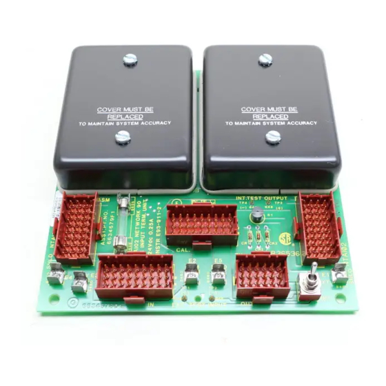
INSTALLATION TABS STANDOFF MOUNTING SCREWS FIELD TERMINATION PANEL T00464A Figure 2-1. Installation for NTAI02 Cable Connections The NTAI02 has five cable connectors. Connector P1 and P2 connect separate NKTU01/11 TU cables to two slave modules for input signal routing. Connector P3 is only used for full scale calibration of IMASM02 modules connected to P1 and P2. -
Page 17: Ntai02 Cable Applications
INSTALLATION ® NIDS01 NKAI01/11 NKTU01/11 IMAMM03 NDIS01 (PRIMARY) NKTU01/11 NTAM01 NKTU01/11 NKDS02/12 OR NKDS01/11 FOR A SINGLE NIDS01 NKAI01/11 IMAMM03 NTAI02 (REDUNDANT) PAIR A TO P4 ON NEXT INTERCONNECTED NTAI02. TO RTD PAIR B THROUGH RTD PAIR D IF REQUIRED. IMASM02 NOTES: 1. - Page 18 INSTALLATION Remove modules from their module mounting unit slots before CAUTION installing or removing a cable assigned to that slot. Failure to do so could result in damage to the module. Retirer le module de son emplacement dans le chassis de montage des modules avant d'installer ou de retirer un câble ATTENTION assigne a cet emplacement.
-
Page 19: Terminal Block Wiring
INSTALLATION ® 10. For redundant IMAMM03 master operation, connect an NKAI01 cable from P4 of the NTAI02 to P1 of the NTAM01. 11. Slide the IMMAM03 into the MMU until the module is fully seated and the faceplate is flush with the front of the rack. Terminal Block Wiring To connect field wiring, the terminal block covers must be removed. -
Page 20: Power Wiring
INSTALLATION TERMINAL BLOCKS TERMINAL BLOCKS TB2A(+) AND TB2B(–) TB1A(+) AND TB1B(–) TB2B(–) TB2A(+) TB1B(–) TB1A(+) THERMOCOUPLE –1 –1 INPUT EXAMPLE –2 –2 COLD JUNCTION –3 –3 COLD JUNCTION –4 –4 MILLIVOLT –5 –5 – INPUT –6 –6 0.25 A FUSE –7 –7 CALIBRATION... - Page 21 INSTALLATION ® The NTAI02 is ready for operation if: 1. The circuit board is mounted in the field termination panel. 2. All required cables are connected to the termination unit. 3. All required field wires are connected to the termination unit and have been verified.
-
Page 22: Section 3 - Maintenance
SECTION 3 - MAINTENANCE INTRODUCTION The NTAI02 Analog Input Termination Unit requires limited maintenance. This section contains a maintenance schedule. MAINTENANCE SCHEDULE Execute the tasks in Table at the specified intervals. Table 3-1. Maintenance Schedule Task Interval Clean and tighten all power and grounding con- nections. -
Page 23: Section 4 - Repair/Replacement Procedures
SECTION 4 - REPAIR/REPLACEMENT PROCEDURES INTRODUCTION This section explains the replacement procedures for the NTAI02 Analog Input Termination Unit. No special tools are required to replace the unit. REPLACEMENT PROCEDURES If an NTAI02 is faulty, replace it with a new one. Do not try to repair the module. -
Page 24: Replacing Fuses
IMAMM03 product instruction. Refer to Section 1 for the current manual identification number. Replacing Fuses Fuse F1 is shipped installed on the TU. It is a 0.25 amp, 250 volt (Bailey part number 194776A12500). The fuse is in fuse holder F1. REPLACEMENT PROCEDURES 4 - 2... - Page 25 REPAIR/REPLACEMENT PROCEDURES Replace the fuse by following these steps: 1. Turn off INFI 90 cabinet power. 2. Install the replacement 0.25 amp fuse into fuse holder F1. 3. Turn on power to the termination unit. REPLACEMENT PROCEDURES I-E96-403A 4 - 3...
-
Page 26: Section 5 - Support Services
SECTION 5 - SUPPORT SERVICES INTRODUCTION Bailey Controls Company is ready to help in the use, applica- tion and repair of its products. Contact the nearest sales office to make requests for sales, applications, installation, repair, overhaul and maintenance contract services. -
Page 27: Appendix A - Thermocouple/Millivolt Slave Input Module (Imasm02
APPENDIX A - THERMOCOUPLE/MILLIVOLT SLAVE INPUT MODULE (IMASM02) INTRODUCTION The Thermocouple Analog Slave Input Module (IMASM02) uses an NTAI02 for termination. Each NTAI02 accepts up to eight thermocouple/millivolt inputs IMASM02. IMASM02 slave modules can connect through separate cables to the NTAI02. Up to four NTAI02s can be interconnected together allowing eight IMASM02s to connect to the IMAMM03. - Page 28 Index NTAI02 Cable Applications .........2-4 Address select switch (SW1)........A-1 Address switch settings (SW1)........A-1 Application example for NTAI02 ......... 1-2 Reference documents..........1-4 Replacement parts............5-1 Replacement procedures..........4-1 Replacing fuses.............4-2 Cable Connections for NTAI02........2-4 Setup/physical installation...........2-2 Features ..............1-1 Cable connections..........2-3 Configuration............2-2 Fuses ..............2-2 Instalation..............2-2...
- Page 29 Telefax 39-10-6582-941 Telephone 49-69-799-0 Telefax 65-292-9011 Telefax 49-69-799-2406 Form I-E96-403A Litho in U.S.A. 692 Copyright © 1992 by Elsag Bailey Process Automation, As An Unpublished Work ® Registered Trademark of Elsag Bailey Process Automation ™ Trademark of Elsag Bailey Process Automation...
Need help?
Do you have a question about the Infi 90 NTAI02 and is the answer not in the manual?
Questions and answers