
Related Manuals for Bailey Infi 90 NICL01


Summary of Contents for Bailey Infi 90 NICL01
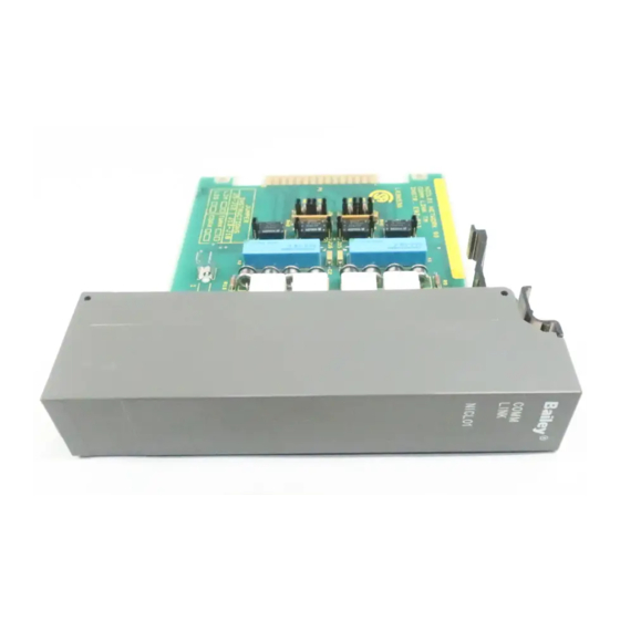
- Page 1 E96-408 ® ® Communication Termination Module (NICL01) Process Control and Automation Solutions from Elsag Bailey Group...
- Page 2 The information contained in this document is subject to change without notice. Elsag Bailey, its affiliates, employees, and agents, and the authors and contributors to this publication specif- ically disclaim all liabilities and warranties, express and implied (including warranties of merchantability and...
- Page 3 This manual explains how to install and use the NICL01. It explains how to set the jumpers, install the cables, mount the termination module and lists maximum cable lengths for the communication loop. ® Registered Trademark of Elsag Bailey Process Automation. I-E96-408A...
- Page 4 ® List of Effective Pages Total number of pages in this manual is 29, consisting of the following: Page No. Change Date Preface Original List of Effective Pages Original iii through vi Original 1-1 through 1-4 Original 2-1 through 2-7 Original Original 4-1 through 4-2...
- Page 5 Safety Summary GENERAL Equipment Environment WARNINGS All components, whether in transportation, operation, or storage must be in a noncorrosive environment. Electrical Shock Hazard During Maintenance Disconnect power or take precautions to ensure that contact with energized parts is avoided when servicing. Special Handling This module uses Electrostatic Sensitive Devices (ESD).
- Page 6 ® Sommaire de Sécurité AVERTISSEMENTS Environment de l'equipement D’ORDRE Ne pas soumettre les composants a une atmosphere corrosive lors GÉNÉRAL du transport, de l'entreposage ou de l'utilisation. Risques de chocs electriques lor de l'entretien S'assurer de debrancher l'alimentation ou de prendre les precau- tions necessaires a eviter tout conatact avec des composants sours tension lors de l'entretien.
-
Page 7: Table Of Contents
Table of Contents Page SECTION 1 - INTRODUCTION ....................1-1 INTRODUCTION......................1-1 INTENDED USER ......................1-1 HARDWARE DESCRIPTION..................1-1 FEATURES........................1-1 INSTRUCTION CONTENT .....................1-1 HOW TO USE THIS MANUAL ..................1-2 NOMENCLATURE ......................1-3 GLOSSARY OF TERMS AND ABBREVIATIONS .............1-3 REFERENCE DOCUMENTS..................1-4 SPECIFICATIONS ......................1-4 SECTION 2 - INSTALLATION .....................2-1 INTRODUCTION......................2-1 SPECIAL HANDLING ....................2-1 UNPACKING AND INSPECTION ..................2-2... - Page 8 ® List of Tables Title Page 2-1. ICL Circuit Boards Revision C Jumper Settings (for LIM or LIS Application) ... 2-3 2-2. ICL Circuit Boards Revision D or Higher Jumper Settings ........2-3 2-3. ICL Cable Applications ..................2-5 3-1. Maintenance Schedule...................
-
Page 9: Section 1 - Introduction
INSTRUCTION CONTENT This manual has five sections and two appendices. Introduction Provides an overview of the ICL. Installation Explains physical installation, wiring and cable requirements, jumper settings, etc. ® Registered trademark of Elsag Bailey Process Automation. INTRODUCTION I-E96-408A 1 - 1... -
Page 10: How To Use This Manual
Explains how to replace the fuse or the module. Procedures Support Services Explains training, documentation and how to order parts from Bailey Controls. Appendices Discuss the modules that can use the ICL and provide a cross-reference of dipswitch and jumper settings for those modules. -
Page 11: Nomenclature
INFI 90/Network 90 termination modules. Twinaxial cable A cable composed of two insulated conductors that are twisted together and are attached or bound together with a common covering. ® Registered trademark of Elsag Bailey Process Automation. NOMENCLATURE I-E96-408A 1 - 3... -
Page 12: Reference Documents
19.7 mA maximum, 15.8 mA typical Mounting Slides into a single slot in the termination mounting unit NTMU01/02. Cooling Requirements No cooling necessary when used in Bailey cabinets and operated within stated environmental limits. Operating Temperature to 70 C (32... -
Page 13: Section 2 - Installation
SPECIAL HANDLING Observe these steps when handling electronic circuitry: NOTE: Always use Bailey's Field Static Kit (P/N 1948385A1 - con- sisting of wrist straps, ground cord assembly, and alligator clip) when working with the modules. The kit connects a technician and the static dissipative work surface to the same ground point to pre- vent damage to the modules by electrostatic discharge. -
Page 14: Unpacking And Inspection
UNPACKING AND INSPECTION 1. Examine the termination module immediately for any ship- ping damage. 2. Notify the nearest Bailey Controls sales office of any dam- age. 3. File a claim for any damage with the transportation com- pany that handled the shipment. -
Page 15: Installing The Fuse
INSTALLATION Installing the Fuse Bailey ships amp/250 volt fuse (Bailey 194776A11001) with each ICL. Verify that the fuse is installed in the fuse holder marked F1. Figure shows the location of the fuse holder on the ICL circuit board. Installing the Jumpers Install the jumpers to match the impedance of the communica- tion cable. -
Page 16: Installing The Termination Module
INSTALLATION ® INSTALLING THE TERMINATION MODULE If the fuse and jumpers are in place, the termination module is ready to install. Installing the Termination Module Cables Before mounting the termination module in the TMU, install the termination cables. Table lists the cables, their applica- tion, connector assignments and length restrictions. -
Page 17: Icl Cable Applications
INSTALLATION 5. If the communication cable or power wiring have not been installed, let the termination module hang out the front of the TMU several inches. This will allow room to install the commu- nication cable and power wiring. After the cables are installed, fully insert the TM until it seats in the cable connector at the rear of the TMU. -
Page 18: Communication Cable Installation
INSTALLATION ® NICL01 NKTL01-3 LOOP 1 NKLS02 INNIS01 LOOP 2 NKCL01 NICL01 NKTL01-3 LOOP 1 LOOP 2 NKTT01 NICL01 LOOP 1 LOOP 2 T00492A Figure 2-3. ICL Cable Connections to the INNIS01 with Coaxial Communication Loop Communication Cable Installation The communication cable connects the ICL to INFI-NET, Plant Loop or to another ICL. -
Page 19: Power Wiring
INSTALLATION POWER WIRING CAUTION We strongly recommend that you turn cabinet power off before doing any termination module wiring. Failure to do so could result in equipment damage. Do not apply power until you ver- ify all wire connections. ATTENTION Il est fortement recommande, de debrancher l'alimentation electrique du cabinet avant d'effectuer toute connexion aux cartes de raccordement du chassis. -
Page 20: Section 3 - Maintenance
SECTION 3 - MAINTENANCE INTRODUCTION The communication termination module requires minimal maintenance. Doing the tasks in Table will provide long, trouble free service. Please note that only qualified personnel should perform maintenance. MAINTENANCE SCHEDULE Table is the maintenance schedule. These tasks are to be performed at the specified intervals. -
Page 21: Section 4 - Repair/Replacement Procedures
FUSE REPLACEMENT If the fuse (F1) opens, replace it with a fuse having an equiva- lent rating. Table describes the fuse and lists its Bailey part number. To replace a fuse: 1. Turn off power to the termination module. 2. Pull on the front cover of the termination module to remove 3. - Page 22 REPAIR/REPLACEMENT PROCEDURES ® CAUTION When removing and replacing an NICL01, all loop communica- tion is lost while the termination module is removed from the loop. ATTENTION Durant le demontage ou le remplacement d'une carte NICL01, toute communication avec le reseau est interrompue et ce pen- dant tout le temps ou la carte est retiree du reseau.
-
Page 23: Section 5 - Support Services
SECTION 5 - SUPPORT SERVICES INTRODUCTION Bailey Controls is ready to help in the use and repair of its products. Contact your nearest sales office to make requests for sales, applications, installation, repair, overhaul and main- tenance contract services. REPLACEMENT PARTS AND ORDERING INFORMATION When making repairs at your facility, order replacement parts from a Bailey sales office. -
Page 24: Appendix A - Network Interface Slave Module Configuration (Innis01
APPENDIX A - NETWORK INTERFACE SLAVE MODULE CONFIGURATION (INNIS01) INTRODUCTION The Network Interface Slave Module (INNIS01) uses the NICL01 to terminate its connection to an INFI-NET ring. A termination cable (NKLS02) connects the NIS to the ICL. The ICL provides a place to connect either coaxial or twinaxial cable from the com- munication loop. - Page 25 NETWORK INTERFACE SLAVE MODULE CONFIGURATION (INNIS01) ® Table A-1. SW1 Node Addresses/SW2 Ring Numbers Example Settings Switch Position Address Example Binary Value Table A-2. Loop Mode Switch (SW3) Settings Pole Setting Function IPL/IIL (Bridge or Gateway). PCU/ICI. ROM Checksum Enabled ROM Checksum Disabled.
-
Page 26: Event Counters
NETWORK INTERFACE SLAVE MODULE CONFIGURATION (INNIS01) Table A-3. Slave Address Switch (SW4) Settings Example Settings Pole Address 1 2 3 0 0 0 0 1 1 1 1 1 Table A-4. Event Counters SW4 Position Description 4 5 6 7 8 0 0 0 0 0 Number of timer interrupts. -
Page 27: Error Counters
NETWORK INTERFACE SLAVE MODULE CONFIGURATION (INNIS01) ® Table A-4. Event Counters (continued) SW4 Position Description 4 5 6 7 8 1 1 0 1 1 Number of Slave Expander Bus NIS-status requests. 1 1 1 0 0 Number of Slave Expander Bus interrupts with invalid status. -
Page 28: Appendix B - Loop Interface Module Configuration (Inlim03
APPENDIX B - LOOP INTERFACE MODULE CONFIGURATION (INLIM03) INTRODUCTION The Loop Interface Module (INLIM03) uses the NICL01 to termi- nate its connection to Plant Loop. A termination cable (NKLS04) connects the LIM to the ICL. The ICL provides a place to connect either coaxial or twinaxial cable from the communi- cation loop. - Page 29 LOOP INTERFACE MODULE CONFIGURATION (INLIM03) ® Table B-1. LIM Event Counter Addresses (S1) (continued) Switch Positions Counter (Binary Address) Description Address Address 1 2 3 4 5 6 7 8 0 0 1 1 0 1 0 0 Messages stored in BIM receive buffer. 0 0 1 1 0 1 0 1 Interrupt Requests (IRQs) sent by BIM.
- Page 30 LOOP INTERFACE MODULE CONFIGURATION (INLIM03) Table B-3. PCU Address Settings (S2) Switch Number Switch Number PCU Address PCU Address 1 2 3 4 5 6 7 8 1 2 3 4 5 6 7 8 0 0 0 0 0 0 0 1 0 0 1 0 0 0 0 1 0 0 0 0 0 0 1 0 0 0 1 0 0 0 1 0...
- Page 31 Index Cable lengths ............. 2-5 Maintenance ...............3-1 Certification ..............1-4 Mounting ..............2-4 Circuit board revision..........2-3 Coaxial cable............1-3, 2-5 Nomenclature..............1-3 Documentation ............5-1 Ordering information ...........5-1 Fuse rating ..............4-1 Fuse replacement............4-1 Power requirements............1-4 Power wiring ...............2-7 Glossary of terms and abbreviations ......1-3 Reference documents..........1-4 Repair procedure ............4-1 Hardware description ..........
- Page 32 Telefax 39-10-6582-941 Telephone 49-69-799-0 Telefax 65-292-9011 Telefax 49-69-799-2406 Form I-E96-408A Litho in U.S.A. 692 Copyright © 1992 by Elsag Bailey Process Automation, As An Unpublished Work ® Registered Trademark of Elsag Bailey Process Automation ™ Trademark of Elsag Bailey Process Automation...
Need help?
Do you have a question about the Infi 90 NICL01 and is the answer not in the manual?
Questions and answers