
Related Manuals for Bailey Infi 90 NIAI02


Summary of Contents for Bailey Infi 90 NIAI02
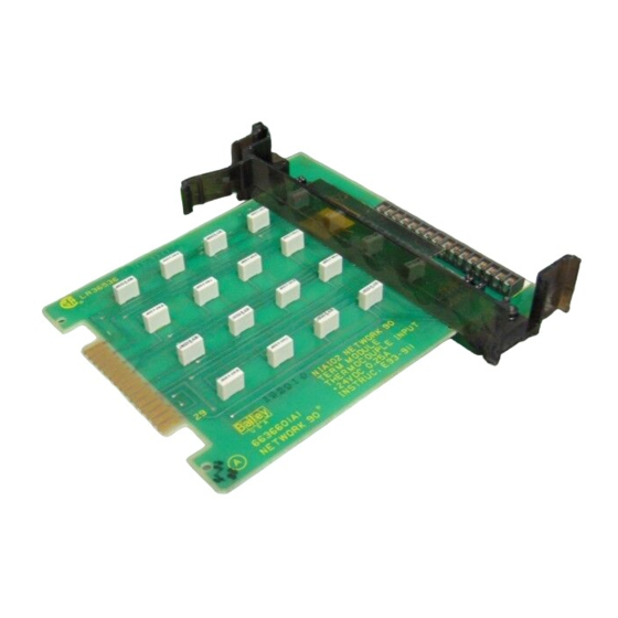
- Page 1 E96-434 ® ® Analog Input Termination Module (NIAI02) Process Control and Automation Solutions from Elsag Bailey Group...
- Page 2 The information contained in this document is subject to change without notice. Elsag Bailey, its affiliates, employees, and agents, and the authors and contributors to this publication specif- ically disclaim all liabilities and warranties, express and implied (including warranties of merchantability and...
- Page 3 This manual explains how to install and use the NIAI02 on the INFI 90 system. It has sections that describe the setup and cabling. The appendix contains information about the IMASM02 module that uses the NIAI02. ® Registered trademark of Elsag Bailey Process Automation. I-E96-434A...
- Page 4 ® List of Effective Pages Total number of pages in this manual is 22, consisting of the following: Page No. Change Date Preface Original List of Effective Pages Original iii through vi Original 1-1 through 1-4 Original 2-1 through 2-6 Original 3-1 Original 4-1 through 4-2...
- Page 5 Safety Summary GENERAL Equipment Environment WARNINGS All components, whether in transportation, operation, or storage must be in a noncorrosive environment. Electrical Shock Hazard During Maintenance Disconnect power or take precautions to ensure that contact with energized parts is avoided when servicing. SPECIFIC Remove modules from their assigned slots before installing a cable CAUTIONS...
- Page 6 ® Sommaire de Sécurité AVERTISSEMENTS Environment de l'equipement D’ORDRE Ne pas soumettre les composants a une atmosphere corrosive lors GÉNÉRAL du transport, de l'entreposage ou de l'utilisation. Risques de chocs electriques lor de l'entretien S'assurer de debrancher l'alimentation ou de prendre les precau- tions necessaires a eviter tout conatact avec des composants sours tension lors de l'entretien.
-
Page 7: Table Of Contents
Table of Contents Page SECTION 1 - INTRODUCTION ....................1-1 OVERVIEW ........................1-1 INTENDED USER ......................1-1 MODULE DESCRIPTION ....................1-1 FEATURES........................1-1 INSTRUCTION CONTENT .....................1-2 HOW TO USE THIS MANUAL ..................1-3 GLOSSARY OF TERMS AND ABBREVIATIONS .............1-3 REFERENCE DOCUMENTS..................1-3 NOMENCLATURE ......................1-4 SPECIFICATIONS ......................1-4 SECTION 2 - INSTALLATION .....................2-1 INTRODUCTION......................2-1 SPECIAL HANDLING ....................2-1 UNPACKING AND INSPECTION ..................2-2... - Page 8 ® List of Tables Title Page 1-1. Glossary of Terms and Abbreviations ..............1-3 1-2. Reference Documents .................... 1-3 1-3. Nomenclature ......................1-4 1-4. Specifications ......................1-4 2-1. NIAI02 Cable Applications ..................2-3 3-1. Maintenance Schedule................... 3-1 A-1. Address Switch Settings (SW1) ................A-1 List of Figures Title Page...
-
Page 9: Section 1 - Introduction
SECTION 1 - INTRODUCTION OVERVIEW One Thermocouple Input Termination Module (NIAI02) is required for each Thermocouple Slave Module (IMASM02). Each NIAI02 can input eight thermocouple or millivolt signals from field equipment to the thermocouple input slave module. The signals pass through the slave module to the Analog Mas- ter Module (IMAMM03). -
Page 10: Application Example For Niai02
Repair/Replacement Details how to replace a TM. Procedures Support Services Describes the support services (repair parts, training, docu- mentation, etc.) available from Bailey Controls Company. Appendix A Shows the cabling needed for the Thermocouple Slave Input Module (IMASM02). INSTRUCTION CONTENT... -
Page 11: Glossary Of Terms And Abbreviations
Analog Master Module and Analog Slave Modules (IMAMM03 and IMASM01/02/03/04) I-E96-420 Thermocouple Calibration Module (NIAC02) I-E96-437 Analog Master Termination Module (NIAM02) I-E96-500 Site Planning and Preparation ® Registered trademark of Elsag Bailey Process Automation. HOW TO USE THIS MANUAL I-E96-434A 1 - 3... -
Page 12: Nomenclature
Atmospheric Pressure Sea level to 3 km (1.86 miles). Air Quality Noncorrosive. Cooling Requirements No cooling is necessary when used in Bailey Controls cabinets and operated within stated limits. Surge Protection Meets IEEE-472-1974 Surge Withstand Capability Test Certification CSA certified for use as process control equipment in an ordinary (non- hazardous) location. -
Page 13: Section 2 - Installation
SPECIAL HANDLING Observe these steps when handling electronic circuitry: NOTE: Always use the Bailey Controls Field Static Kit (part number 1948385A1 - consisting of two wrist straps, ground cord assembly, alligator clip, and static dissipating work surface) when working with modules. -
Page 14: Unpacking And Inspection
1. Examine the module to make sure that no damage has occurred in transit. 2. Notify the nearest Bailey Controls sales office of any damage. 3. File a claim for any damage with the shipping company that handled the shipment. -
Page 15: Niai02 Cable Applications
INSTALLATION TO ADDITIONAL NDIS01 TO REDUNDANT NDIS01 NIAM02 6634408 2 NKTD02/12 NIAM02 NKTM01 NKTU02/12 IMAMM03 –3 NKTM01 TO MMU NKTU02/12 NIAC02 CALIBRATION SLOT 6634408 2 –1 6634408 2 NKTM01 NKTU02/12 NIAI02 NIAI02 IMASM02 (½ RTD A) (½ RTD C) 6634408 2 6634408 2 NKTM01 NKTU02/12... - Page 16 1. Pull the termination module several inches from the TMU backplane. 2. If round type cables are already installed in the TMU, remove the cable retaining bracket (Bailey part number 258436A1). Use NKTU02/12 or NKTMU01 cables. Round cables and ribbon cables can be mixed when installing multi- ple TMs.
-
Page 17: Termination Module Installation
INSTALLATION Termination Module Installation The NIAI02 inserts into a standard INFI 90 termination mount- ing unit (TMU) and occupies one slot. To install: 1. Verify slot assignment of the NIAI02 module. 2. Align the NIAI02 module with the guide rails in the TMU and partially insert the module. -
Page 18: Power Wiring
INSTALLATION ® Power Wiring CAUTION If input or output circuits are a shock hazard after disconnect- ing system power at the power entry panel, then the door of the cabinet containing these externally powered circuits must be marked with a warning stating that multiple power sources exist. -
Page 19: Section 3 - Maintenance
SECTION 3 - MAINTENANCE INTRODUCTION The Analog Input Termination Module (NIAI02) requires limited maintenance. This section contains a maintenance schedule. MAINTENANCE SCHEDULE Execute the tasks in Table 3-1 at the specified intervals. Table 3-1. Maintenance Schedule Task Interval Clean and tighten all power and Every 6 months or during plant grounding connections. -
Page 20: Section 4 - Repair/Replacement Procedures
SECTION 4 - REPAIR/REPLACEMENT PROCEDURES INTRODUCTION This section explains the replacement procedures for the Ana- log Input Termination Module (NIAI02). No special tools are required to replace the module. REPLACEMENT PROCEDURES If a NIAI02 is faulty, replace it with a new one. Do not try to repair the module. - Page 21 REPAIR/REPLACEMENT PROCEDURES ® 6. Connect all power and field wiring removed in Step 3. 7. Verify that wiring and cabling to the TM is correct. 8. Fully insert the termination module into the TMU. 9. Replace the termination module front cover. 10.
-
Page 22: Section 5 - Support Services
SECTION 5 - SUPPORT SERVICES INTRODUCTION Bailey Controls Company is ready to help in the use, applica- tion and repair of its products. Contact the nearest sales office to make requests for sales, applications, installation, repair, overhaul and maintenance contract services. -
Page 23: Appendix A - Thermocouple Slave Input Module (Imasm02
APPENDIX A - THERMOCOUPLE SLAVE INPUT MODULE (IMASM02) INTRODUCTION The Thermocouple Analog Slave Input Module (IMASM02) uses an NIAI02 for termination of field wiring. Each NIAI02 accepts up to eight thermocouple or millivolt inputs. This appendix contains figures and tables that show the dipswitch location on the IMASM02 and its settings. - Page 24 Index Address select switch (SW1)........A-1 Reference documents..........1-3 Address switch settings (SW1)........A-1 Replacement parts............5-1 Application example for NIAI02 ........1-2 Replacement procedures..........4-1 Cable connections for NIAI02........2-3 Setup/physical installation...........2-2 Cable connections..........2-2 Cable installation ...........2-2 Power wiring............2-6 Glossary of terms and abbreviations ......1-3 Terminal wiring............2-5 Termination module installation ......2-5 Special handling............2-1...
- Page 25 Telefax 39-10-6582-941 Telephone 49-69-799-0 Telefax 65-292-9011 Telefax 49-69-799-2406 Form I-E96-434A Litho in U.S.A. 592 Copyright © 1992 by Elsag Bailey Process Automation, As An Unpublished Work ® Registered Trademark of Elsag Bailey Process Automation ™ Trademark of Elsag Bailey Process Automation...
Need help?
Do you have a question about the Infi 90 NIAI02 and is the answer not in the manual?
Questions and answers