
Related Manuals for Bailey infi 90 NTAI05


Summary of Contents for Bailey infi 90 NTAI05
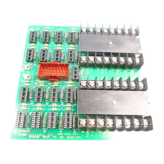
- Page 1 E96-416 ® ® Analog Input Termination Unit (NTAI05) Process Control and Automation Solutions from Elsag Bailey Group...
- Page 2 The information contained in this document is subject to change without notice. Elsag Bailey, its affiliates, employees, and agents, and the authors and contributors to this publication specif- ically disclaim all liabilities and warranties, express and implied (including warranties of merchantability and...
- Page 3 This manual explains how to install and use the NTAI05 termi- nation unit in the INFI 90 system. It contains sections that describe setup and cabling. The appendices contain data about the IMASM01, IMFBS01, and IMASI02 modules. ® - Registered trademark of Elsag Bailey Process Automation. I-E96-416B...
- Page 4 ® List of Effective Pages Total number of pages in this instruction is 28, consisting of the following: Page No. Change Date Preface Original List of Effective Pages Original iii through vi Original 1-1 through 1-5 Original 2-1 through 2-7 Original Original 4-1 through 4-2...
- Page 5 Safety Summary GENERAL Equipment Environment WARNINGS All components, whether in transportation, operation or storage, must be in a noncorrosive environment. Electrical Shock Hazard During Maintenance Disconnect power or take precautions to insure that contact with energized parts is avoided when servicing. SPECIFIC Remove modules from their module mounting unit slots before CAUTIONS...
- Page 6 ® Sommaire de Sécurité AVERTISSEMENTS Environnement de l’équipement D’ORDRE Ne pas soumettre les composants à une atmosphère corrosive lors GÉNÉRAL du transport, de l’entreposage ou l’utilisation. Possibilité de chocs électriques durant l’entretien Débrancher l’alimentation ou prendre les précautions pour éviter tout contact avec des composants sous tension durant l’entretien.
-
Page 7: Table Of Contents
Table of Contents Page SECTION 1 - INTRODUCTION ....................1-1 OVERVIEW ........................1-1 INTENDED USER ......................1-1 TERMINATION UNIT DESCRIPTION ................1-1 FEATURES........................1-1 INSTRUCTION CONTENT .....................1-3 HOW TO USE THIS MANUAL ..................1-3 REFERENCE DOCUMENTS..................1-3 GLOSSARY OF TERMS AND ABBREVIATIONS .............1-4 SPECIFICATIONS ......................1-4 NOMENCLATURE ......................1-5 SECTION 2 - INSTALLATION .....................2-1 INTRODUCTION......................2-1 SPECIAL HANDLING ....................2-1... - Page 8 ® List of Tables Title Page 1-1. Reference Documents .................... 1-3 1-2. Glossary of Terms and Abbreviations ..............1-4 1-3. Specifications ......................1-4 1-4. Nomenclature ......................1-5 2-1. Dipshunt Settings for NTAI051 Termination Unit ........... 2-3 2-2. NTAI05 Cable Applications ..................2-4 3-1.
-
Page 9: Section 1 - Introduction
The NTAI05 Analog Input Termination Unit inputs 15 or 16 channels of analog signals depending on slave module type. It connects a slave module to field equipment and Bailey Controls smart transmitters. The signals pass through slave modules to the IMMFP01, IMMFP02 and IMMFP03 INFI 90 Multi-Function Processors, IMAMM03 Analog Master Modules or NMFC03, NMFC04 and NMFC05 Multi-Function Controllers. -
Page 10: Application Example For The Ntai05 Termination Unit
INTRODUCTION ® COMMUNICATION HIGHWAY (INFI-NET OR PLANT LOOP) COMMUNICATION MODULES MODULE BUS IMMFP01/02/03 IMAMM03 OTHER MODULES SLAVE EXPANDER BUS SLAVE EXPANDER BUS IMASM01 IMASI02 STT02 IMFBS01 OTHER SLAVES NTAI05 NTAI05 NTAI05 ANALOG ANALOG ANALOG INPUTS INPUTS INPUTS T00583A Figure 1-1. Application Example for the NTAI05 Termination Unit Analog inputs routed between field devices and I/O •... -
Page 11: Instruction Content
Details how to replace an NTAI05 unit. Procedures Support Services Describes the support services (repair parts, training, docu- mentation, etc.) available from Bailey Controls Company. Appendix A Shows the IMASI02 Analog Slave Input Module. Appendix B Shows the IMASM01 Analog Slave Module. -
Page 12: Glossary Of Terms And Abbreviations
Sea level to 3 km (1.86 mi). Air Quality Noncorrosive. Cooling Requirements No cooling is necessary when used in Bailey cabinets and operated within stated limits. Certification CSA certified for use as process control equipment in an ordinary (nonhazardous) location. -
Page 13: Nomenclature
INTRODUCTION NOMENCLATURE Table contains the modules and equipment that can be used with the NTAI05 termination unit. Table 1-4. Nomenclature Nomenclature Description IMASI02 Analog Input Slave Module IMASM01 Analog Slave Module IMFBS01 Field Bus Slave Module NFTP01 Field Termination Panel NKTU01 Cable, Termination Unit (PVC) NKTU11... -
Page 14: Section 2 - Installation
SPECIAL HANDLING Observe these steps when handling electronic circuitry: NOTE: Always use the Bailey Controls Field Static Kit (part number 1948385A1 - consisting of two wrist straps, ground cord assembly, alligator clip and static dissipating work surface) when working with modules. -
Page 15: Unpacking And Inspection
These are steps to follow for general handling: 1. Examine the unit to make sure that no damage has occurred in transit. 2. Notify the nearest Bailey Controls Sales/Service Office of any damage. 3. File a claim for any damage with the shipping company that handled the shipment. -
Page 16: Installation For Ntai05 Termination Unit
INSTALLATION Table 2-1. Dipshunt Settings for NTAI05 Termination Unit Application/Signal Type Dipshunt Configuration Dipshunt Locations Connecting Cable System powered 4-20 mA ‘ Externally powered 4-20 mA XU1-XU15 on IMASI02 or IMFBS01 Single ended voltage XU1-XU16 on IMASM01 Differential voltage NKTU01/11 IMASI01, IMFBS01 IMASM01 XU17... -
Page 17: Cable Connections
INSTALLATION ® Cable Connections The NTAI05 termination unit has one cable connector (P1) to provide analog inputs to the slave module. Install the termina- tion connector cable (NKTU01) to connect the termination unit to the slave module for communication. See Figure for the termination unit cable connections. -
Page 18: Terminal Block Wiring
Connect the wiring to the termination unit terminals from the input devices sensing the process. Input devices may be: BC/ BCN series Bailey Controls Pressure Transmitters, EQ/EQN series Bailey Controls Temperature Transmitters, pH series Bailey Controls pH/TBN Transmitters or any conventional transmitter. -
Page 19: Ntai05 Typical Input Circuit
INSTALLATION ® +24 V TO SLAVE + 30 150 Ω MODULE – 29 4.7 MΩ FIELD 4.7 MΩ WIRING 9 10 11 12 13 14 15 16 XU12 8 7 6 5 4 3 2 1 250 Ω ANALOG INPUT 12 –... -
Page 20: Power Wiring
INSTALLATION Power Wiring This section explains how to connect power wiring. The NTAI05 unit has two fast-on connections for power and I/O common. Make power connections to the termination unit after it is mounted in the NFTP01 termination panel. Make sure cabinet and I/O power are turned off before connecting ground and power wiring. -
Page 21: Section 3 - Maintenance
SECTION 3 - MAINTENANCE INTRODUCTION The NTAI05 Analog Input Termination Unit requires limited maintenance. This section contains a maintenance schedule. MAINTENANCE SCHEDULE Execute the tasks in Table 3-1 at the specified intervals. Table 3-1. Maintenance Schedule Task Interval Clean and tighten all power and grounding connections. -
Page 22: Section 4 - Repair/Replacement Procedures
SECTION 4 - REPAIR/REPLACEMENT PROCEDURES INTRODUCTION This section explains the replacement procedures for the NTAI05 Analog Input Termination Unit. REPLACEMENT PROCEDURES If a termination unit is faulty, replace it with a new one. Do not try to repair the module. Replacing components may affect per- formance and certification. - Page 23 REPAIR/REPLACEMENT PROCEDURES ® 4. Label and disconnect the cable connected to the termina- tion unit. 5. Label and disconnect system I/O power and ground wires from the terminals. 6. Remove the two number 10 screws securing the termina- tion unit to the field termination panel. 7.
-
Page 24: Section 5 - Support Services
SECTION 5 - SUPPORT SERVICES INTRODUCTION Bailey Controls Company is ready to help in the use, applica- tion and repair of its products. Contact the nearest sales office to make requests for sales, applications, installation, repair, overhaul and maintenance contract services. -
Page 25: Appendix A - Imasi02 Analog Slave Input Module
IMASI02 slave accepts inputs of four to 20 milliamps, one to five VDC, zero to one VDC, zero to five VDC, zero to ten VDC and -10 VDC to +10 VDC (Bailey Controls smart transmitters). This appendix contains figures and tables that show dipswitch locations on the IMASI02 slave and its settings. -
Page 26: Introduction
APPENDIX B - IMASM01 ANALOG SLAVE MODULE INTRODUCTION The IMASM01 Analog Slave Module uses an NTAI05 unit for termination. Dipshunts on the NTAI05 termination unit config- ure the sixteen analog inputs for the IMASM01 slave. The IMASM01 slave accepts inputs of four to 20 milliamps and one to five VDC, zero to five VDC, zero to ten VDC, and -10 to +10 VDC. - Page 27 IMASM01 ANALOG SLAVE MODULE ® Table B-1. IMASM01 Address Switch Settings (SW1/SW2) Switch Position Switch Position Address Address Example Example OPEN = OFF = 1 CLOSED = ON = 0 B - 2 I-E96-416B...
- Page 28 Index Analog slave input module (IMASI02) ......A-1 Nomenclature..............1-5 Analog slave module (IMASM01) ....... B-1 NTAI05 termination unit ..........2-4 Application example for NTAI05 ......... 1-2 Cable connections..........2-4 Input circuit............2-6 Cable connections ............2-4 Overview ..............1-1 Dipshunt settings IMASI02/IMFBS in point-to-point mode ....A-1 Reference documents..........1-3 IMASM01 ..............
- Page 29 Telefax 39-10-6582-941 Telephone 49-69-799-0 Telefax 65-292-9011 Telefax 49-69-799-2406 Form I-E96-416B Litho in U.S.A. 992 Copyright © 1992 by Elsag Bailey Process Automation, As An Unpublished Work ® Registered Trademark of Elsag Bailey Process Automation ™ Trademark of Elsag Bailey Process Automation...
Need help?
Do you have a question about the infi 90 NTAI05 and is the answer not in the manual?
Questions and answers