Table of Contents
Advertisement
Quick Links
Advertisement
Table of Contents

Related Manuals for Skov DA 3800


Summary of Contents for Skov DA 3800
- Page 1 DA 3800 Flange Inlet Mounting Guide 604351 • 2021-03-17...
- Page 3 The date of change appears from the front and back pages. Note • All rights belong to SKOV A/S. No part of this manual may be reproduced in any manner whatsoever without the expressed written permission of SKOV A/S in each case.
-
Page 4: Table Of Contents
DA 3800 Flange Inlet 1 Product description............................ 5 2 Product survey ............................... 6 Flange inlet .......................... 7 Accessories.......................... 7 3 Mounting guide............................. 10 Recommended tools........................ 10 Mounting of sandwich screws.................... 11 Wall inlet positioning....................... 12 Mounting inlet .......................... 12 3.4.1 Preparing hole in wall......................... 12 3.4.2... -
Page 5: Product Description
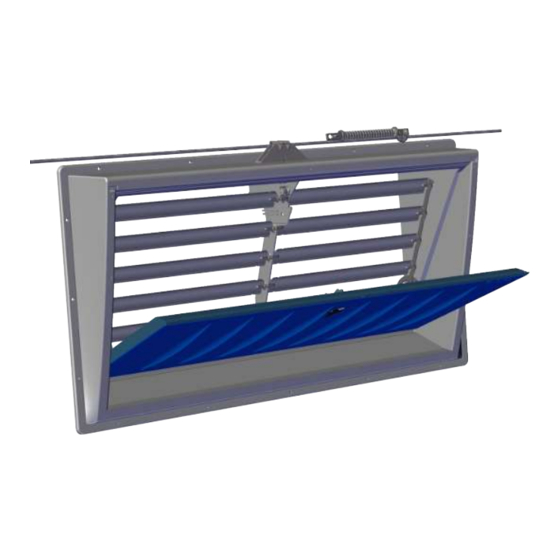
DA 3800 Flange Inlet 1 Product description The DA 3800 flange inlet is a large universal wall inlet, which is used for ventilating livestock houses with LPV or Combi-Tunnel ventilation. The flange inlet can be adapted to wall thicknesses up to 35 cm employing an extension piece. The inlet is fixed on the inside wall by screws through the flange itself. -
Page 6: Product Survey
DA 3800 Flange Inlet 2 Product survey Shield Hen net Dimmer Inlet funnel Air direction baffle Wall gasket Air intake louver kit Outside flange Extension rod Extension piece Flange inlet Mounting Guide... -
Page 7: Flange Inlet
DA 3800 Flange Inlet 2.1 Flange inlet 433354 DA 3800 AFC flange inlet w/inlet funnel It is used for ventilation of livestock buildings. The flange inlet is available with Advanced Flow Control (AFC), which provides high pressure stability and optimum airflow from minimum to maximum ventilation. - Page 8 One per inlet. 433375 DA 3800 screw kit f/outside flange Used when mounting the DA 3800 outside flange in sandwich walls. 433359 DA 3800 extension rod 40 cm The extension rod is used if you want to run the pull rod round heavy con- crete pillars or the like, where it is not possible to run the pull rod directly through the pillar by making a through-going hole.
- Page 9 One per inlet. 433381 DA 3800 wall gasket Used as a gasket between the wall and DA 3800 flange inlet. Can in most cases replace the manual point process. To be mounted on the inlet frame. One per inlet.
-
Page 10: Mounting Guide
DA 3800 Flange Inlet 3 Mounting guide Check that all ordered parts are present and undamaged prior to starting the work. Read the directions carefully before starting mounting. 3.1 Recommended tools See a list of tools recommended for the installation of the flange inlet below. -
Page 11: Mounting Of Sandwich Screws
DA 3800 Flange Inlet Item Description Chisel Ladder Jigsaw Spirit level Try square 3.2 Mounting of sandwich screws To ensure that the screw makes the right thickening and the best possible thread on the back, the correct hole must be drilled first and the screwing must be done with the correct momentum depending on the thickness of the metal in the sandwich panel. -
Page 12: Wall Inlet Positioning
The positioning of the inlet in a wall depends on the layout of the building and the house layout. The positioning may therefore only be made according to directions communicated by SKOV or representatives of the company. The inlet must be placed horizontally in the wall. The inlet flap must be pointing into the house. - Page 13 DA 3800 Flange Inlet Remember always to use a spirit level. Drill four holes of roughly 10 mm right through the wall. Cut the holes. Mounting Guide...
-
Page 14: Mounting Clamp For The Pull Rod
Parts in a bag and where they are used Picture Num- Type Application DA 3800 bracket for the pull rod. Used in section, Mounting clamp for the pull rod [} 14]. PT screw 5x16, flange, TX25. Tightenedwith 2 Nm Tunnel inlet, bushing L= 17.5. - Page 15 DA 3800 Flange Inlet Mount the holder for the pull rod using the two enclosed screws (2 Nm). Mounting Guide...
-
Page 16: Mounting Inlet In Wall
DA 3800 Flange Inlet 3.4.3 Mounting inlet in wall Make sure that the inlet flap is closed. In the case of sloping walls, make sure not to tighten the screws too much so that the inlet frame becomes oblique, preventing the inlet flap from closing tightly. See section Oblique walls [} 18]. -
Page 17: Mounting The Activation Lever
DA 3800 Flange Inlet 3.4.4 Mounting the activation lever Open inlet. 1. Mount the activation lever on the guide bar on both sides. 2. Turn the activation lever. 3. Press the activation lever into the slot. 3.4.5 Mounting safety strip Open inlet. -
Page 18: Oblique Walls
DA 3800 Flange Inlet 3.4.6 Oblique walls If the inside wall is sloping, you may have to mount a heavy-duty plate or wedges between the inlet and the wall to avoid distortion of the inlet. It is essential to adjust for the distortion when mounting in sloping walls. -
Page 19: Foaming
DA 3800 Flange Inlet 3.4.7 Foaming SKOV A/S recommends using single-component polyurethane foam or similar. Check before foaming how much the foam expands. Wet the faces with water from a mist sprayer before proceeding with the foaming. Foam around the inlet, as shown in the drawing. Foam the entire depth of the wall in the corners of the inlet and approx. -
Page 20: Pointing
DA 3800 Flange Inlet 3.4.8 Pointing SKOV A/S recommends Sikaflex AT Connection or MS polymer single-component or similar. If the wall gasket is chosen, it can in most cases re- place the manual point process. See section Wall gas- ket [} 33]. -
Page 21: Check The Mounting
DA 3800 Flange Inlet 3.4.9 Check the mounting Check that all the edges are tight and that the inlet flap closes tightly at both ends. Mounting Guide... -
Page 22: Mounting Pull Rod And Reel
DA 3800 Flange Inlet 3.5 Mounting pull rod and reel Press the sides of the holder for the pull rod to open the clamp for pull rod. Mount the pull rod in the two slots. The black arrow shows the tensile direction. - Page 23 The cord for the spring unit must be above the reel. Close the clamp for the pull rod. For mounting the actuator, see document Technical User Manual for DA 175 actuator. The tensile length for DA 3800 flange inlet is 455 mm. Mounting Guide...
-
Page 24: Release For Cord When Servicing
DA 3800 Flange Inlet 3.5.1 Release for cord when servicing It is possible to service one single inlet while the other in- lets continue to function. Turn the release lock in the spring unit. Pull the release lock out. Turn the release lock out. -
Page 25: Coil Spring
DA 3800 Flange Inlet 3.5.2 Coil spring Mount the bracket on the wall 1200 mm from the inlet. Mount the coil spring on the bracket. The actuator that opens and closes the inlet must be in the home position, and the inlet must be closed. -
Page 26: Spring Unit On Pull Rod
DA 3800 Flange Inlet 3.5.3 Spring unit on pull rod The differential switch on the flap and frame must be set (click) to standard opening before pulling the spring unit. Perhaps see section Advanced Inlet Control (AIC) [} 27] Position of the differential switch on the flap. -
Page 27: Advanced Inlet Control (Aic)
DA 3800 Flange Inlet 3.5.4 Advanced Inlet Control (AIC) 3.5.4.1 Standard opening The symbol for standard opening (factory setting). The differential switch on the frame is set for standard opening. The differential switch on the flap is set for standard opening. -
Page 28: Differential Opening
DA 3800 Flange Inlet 3.5.4.2 Differential opening The symbol for AIC (Advanced Inlet Control). Use a screwdriver to pull the differential switch on the frame slightly apart. Set the differential switch on the frame to AIC. Turn the differential switch on the flap counterclockwise (click) for AIC (Advanced Inlet Control). -
Page 29: From Differential To Standard Opening
DA 3800 Flange Inlet 3.5.4.3 From differential to standard opening Use a screwdriver to pull the differential switch on the frame slightly apart. Set the differential switch on the frame to standard opening. Turn the differential switch on the flap clockwise (click) for standard opening. -
Page 30: Mounting Accessories
DA 3800 Flange Inlet 3.6 Mounting accessories 3.6.1 Inlet funnel The arrow on the inlet funnel must face upward. Tilt the inlet funnel onto the inlet, starting at the bottom and then moving upward. Make sure that the insulation piece is attached to the inlet funnel. -
Page 31: Extension Piece
DA 3800 Flange Inlet 3.6.2 Extension piece Point the groove with a small joint sealant before mount- ing the insulation piece. For recommended sealant, see section Pointing [} 20]. Mount the insulation piece from the inlet funnel. Point the groove in the insulation piece with a small joint sealant before mounting the extension piece. - Page 32 DA 3800 Flange Inlet Adapt the insulation piece with a knife before mounting in wall. Mount the inlet funnel on the flange with three screws. Mounting Guide...
-
Page 33: Wall Gasket
DA 3800 Flange Inlet 3.6.3 Wall gasket Mount the wall gasket on the entire inlet edge before mounting the inlet in the wall. The wall gasket is assembled at the bottom of the inlet. 3.6.4 Outside flange for wall inlet Outside flange fits different wall thicknesses. - Page 34 DA 3800 Flange Inlet Press the bottom part of the flange up against the inlet. Mount the outside flange on the wall using 14 screws and washers. The screws must be mounted so that the flange can ex- pand and contract at changing temperatures. Tighten the screws lightly and then loosen half a turn.
-
Page 35: Screen
DA 3800 Flange Inlet 3.6.5 Screen If the inlet is fitted with outside cover. Mark the drill holes for the screen on both sides. Place the bracket on the guide pins on the outside cover. Mark where the two top screws should be screwed in. - Page 36 DA 3800 Flange Inlet Measure 143 mm. 143 mm Place the bracket and mark where the two top screws should be screwed in. Remove the bracket. Screw the two screws halfway. The screen sides are marked L = left and R = right.
- Page 37 DA 3800 Flange Inlet Mount five air intake louvers on the right screen side. Mount the left screen side on the air intake louvers. Mounting Guide...
- Page 38 DA 3800 Flange Inlet Mount the support of the screen. Mount the bracket of the screen. Click the bracket onto the screen support. Mount the screen, including bracket on the two screws. Mounting Guide...
- Page 39 DA 3800 Flange Inlet Mount the screen on the wall using three screws on each side and the two bottom screws of the bracket. If the inlet is fitted without outside cover, use a spirit level to ensure that the screen is level.
-
Page 40: Air Direction Baffle
DA 3800 Flange Inlet 3.6.6 Air direction baffle Drill five Ø3.5 holes according to the markings. Mount the holder and the air direction baffle using a screw. Mount the left side piece on the air direction baffle. Mounting Guide... - Page 41 DA 3800 Flange Inlet Screw the left side piece onto the inlet. Mount the right side piece in the same way as the left side piece. Place the two positioning locks in the desired position above the air direction baffle.
-
Page 42: Extension Rod
DA 3800 Flange Inlet 3.6.7 Extension rod The extension rod is applied if there are obstacles such as heavy-duty concrete pillars, or the like, up to 240/400mm and where it is not possible to run the pull rod directly through. - Page 43 DA 3800 Flange Inlet Mount the 1850 mm string on the differential switch with one double knot. Pull the string through the holder for the pull rod. See also section Mounting pull rod and reel [} 22]. Mount the string on the extension rod.
-
Page 44: Hen Net
DA 3800 Flange Inlet 3.6.8 Hen net Mount the four brackets for the hen net using screws in the existing screw holes in the inlet frame. Make sure that the screws are long enough. Mount the hen net in the four brackets. -
Page 45: Louver Kit
DA 3800 Flange Inlet 3.6.9 Louver kit Mount the guide bar on the air intake louvers on both sides. Dismantle the differential switch on the frame. Use a screwdriver to pull the differential switch on the frame slightly apart. Perhaps see section Advanced Inlet Control (AIC) [} 27]. - Page 46 DA 3800 Flange Inlet Click the air intake louver kit into the five grooves in the center pillar. Mount the air intake louver kit on the two frame sides. Mount the switch. Turn the differential switch to the required position.
-
Page 47: Dimmer
DA 3800 Flange Inlet 3.6.10 Dimmer Mount the 2 damper hooks on the front of the frame. Press the damper so that it clicks onto the back of the frame. Press the damper and see if it returns. Check that the louvers (AFC) can move freely. -
Page 48: Maintenance
DA 3800 Flange Inlet 4 Maintenance The flap must be open and then closed during cleaning. The product may be cleaned by a high-pressure cleaner without using: • solvents • corrosive/caustic agents 4.1 Recycling/Disposal Products suitable for recycling are marked with a pictogram. -
Page 49: Technical Data
Tensile force per inlet Tensile length with spring unit on pos. 1 Air output at -10 Pa, wall thickness 5-35 cm 3800 DA 3800 flange inlet w/inlet funnel + 3600 DA 3800 flange inlet w/inlet funnel + AFC and shield 3950... -
Page 50: Dimensioned Sketch
DA 3800 Flange Inlet 5.1 Dimensioned sketch In mm. 5.1.1 DA 3800 1067 Hole in wall 950 5.1.2 Inlet funnel Mounting Guide... -
Page 51: Air Direction Baffle
DA 3800 Flange Inlet 5.1.3 Air direction baffle 80° 5.1.4 Shield 1097 5.1.5 Hen net 1087 Mounting Guide... - Page 52 SKOV A/S • Hedelund 4 • Glyngøre • DK-7870 Roslev Tel. +45 72 17 55 55 • www.skov.com • E-mail: skov@skov.dk...
Need help?
Do you have a question about the DA 3800 and is the answer not in the manual?
Questions and answers