Table of Contents
Advertisement
Quick Links
Advertisement
Table of Contents

Related Manuals for Skov DOL 278AMT-1


Summary of Contents for Skov DOL 278AMT-1
- Page 1 DOL 278AT Emergency Opening Technical Manual 603923 • 2023-10-13...
- Page 2 The date of change appears from the front and back pages. Note • All rights belong to SKOV A/S. No part of this manual may be reproduced in any manner whatsoever without the expressed written permission of SKOV A/S in each case.
-
Page 3: Table Of Contents
DOL 278AT 1 Product description ............................ 4 2 Procedure................................ 5 3 Product survey ............................... 6 4 Mounting guide............................... 7 Mounting of climate sensors .................... 8 5 Installation guide............................ 9 Installation of battery......................... 9 Installation of the TEST supply separator ................ 9 Cable dimensions for 24V DC depending on length ............ -
Page 4: Product Description
DOL 278AT 1 Product description DOL 278T is an advanced emergency opening unit providing optimum safety in connection with technical fail- ures. This is achieved by means of a separate temperature sensor and manual setting of the temperature limit for emergency opening. DOL 278T opens only as much as needed. DOL 278T is specially designed for harsh livestock house environments. -
Page 5: Procedure
DOL 278AT 2 Procedure This manual describes the mounting, installation and commissioning of a DOL 278T controlled emergency opening system and is aimed primarily at the technicians and electricians who will be mounting, installing and testing the emergency opening system. The following checklist indicates the main points of the work flow regarding set up of the emergency opening system. -
Page 6: Product Survey
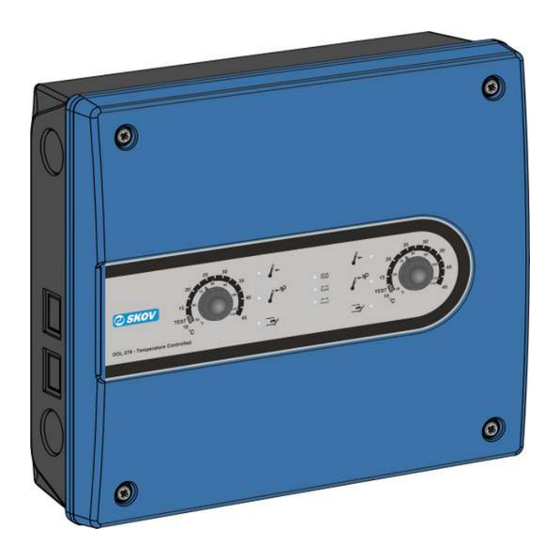
DOL 278AT 3 Product survey 134692 DOL 278AMT-1 EmergencyOpen Temp Medium 4.2A Temperature-controlled emergency opening in a one-house version. Max. power consumption: 4.2 A Battery: 4 Ah Two temperature sensors are included (1 inside temperature sensor + 1 outside temperature sensor). -
Page 7: Mounting Guide
DOL 278AT 4 Mounting guide 1. Drill holes in the bottom of the cabinet (A). 2. Place the emergency opening unit: - close enough to the house controller for the rubber sleeve supplied (B) to fit neatly between them (the emergency opening unit can be placed on either side of the house controller). -
Page 8: Mounting Of Climate Sensors
DOL 278AT 4.1 Mounting of climate sensors • Never use a plug on the DOL 12 temperature sensor as a bad connection here could have disas- trous results. • Never use shrink-on sleeves when splicing wires inside the livestock house. Use a contact box. Placing of sensors inside the house •... -
Page 9: Installation Guide
DOL 278AT 5 Installation guide Installation, servicing and troubleshooting of all electrical equipment must be carried out by quali- fied personnel in compliance with the applicable national and international standard EN 60204-1 and any other EU standards that are applicable in Europe. The installation of a power supply isolator is required for each motor and power supply to facilitate voltage-free work on the electrical equipment. -
Page 10: Cable Dimensions For 24V Dc Depending On Length
DOL 278AT 5.3 Cable dimensions for 24V DC depending on length 2 A motor 4 A motor 8 A motor 10 A motor AWG Cross Length Length Length Length section 0 - 41 m 0 - 20 m 1.5 mm 42 –... -
Page 11: Connection To The House Controller
DOL 278AT 5.5 Connection to the house controller 1. Remove the jumper plug (A) (place it in the bottom of the cabinet). 2. Connect the enclosed connecting cable (B). 3. Fasten the six conductors in the terminal block (C) Q1-Q5 and F6. 4. -
Page 12: Setting Of Jumpers
DOL 278AT 5.5.1 Setting of jumpers Jumper adjustment should be carried out while there is no voltage across the PCB. Function Jumper Setting (period for air inlet) Outside tempera- J7 (F) OFF: Outside temperature compensation not active ture compensa- ON: Outside temperature compensation active (fac- tion tory setting) Run time... -
Page 13: Setup Options At High Power Consumption
DOL 278AT 5.6 Setup options at high power consumption When the distance between the climate controller and wall fan or actuator is long, you can avoid long, thick low- power cables by placing DOL 278 ON/OFF close to the power-consuming units. An unlimited number of DOL 278 ON/OFF can be installed close to wall fans and actuators to supply 24 V DC. -
Page 14: Cable Plan
DOL 278AT 5.7 Cable plan Shady side House 2 House 1 Service room Controller Emergency opening Power supply Only two-house Technical Manual... -
Page 15: Wiring Diagrams
DOL 278AT 5.8 Wiring diagrams 5.8.1 Emergency opening - Medium Emergency opening - Medium Winch motor - chimney Winch motor - wall House controller Technical Manual... -
Page 16: Emergency Opening - Large
DOL 278AT 5.8.2 Emergency opening - Large Emergency opening - Large Winch motor - chimney Winch motor - wall House controller Technical Manual... -
Page 17: Emergency Opening - Temperature Controlled And With Dol 278 On/Off
DOL 278AT 5.8.3 Emergency opening - Temperature controlled and with DOL 278 ON/ DOL 278T placed at climate controller and DOL 278 ON/OFF placed at fan. DOL 278 ON/OFF is used as extra power supply. No. 2 No. 1 Climate controller Emergency opening Jumper in climate controller DOL 278 ON/OFF no. -
Page 18: Number Of Fans And Actuators On Emergency Opening
DOL 278AT 5.9 Number of fans and actuators on emergency opening The table states the maximum number of fans and actuators that can be connected to DOL 278 ON/OFF, when DOL 278 ON/OFF is used as additional 24 V DC power supply. DOL 278AM emergency DOL 278AL emergency DOL 278AXL emergency... - Page 19 DOL 278AT Yes: When the control fails, the air outlet is active. No: When the control fails, the air outlet is inactive. Side cooling Yes: When the control fails, side cooling is active and runs until the emergency situation is over. No: When the control fails, the side cooling is not active.
-
Page 20: Testing
DOL 278AT 6 Testing 6.1 Lamp indications Flashing sequence Cause Outdoor temperature compensation active: Switches on in the relevant side(s) (yellow). 2 sec. - endless Misplaced outside sensor: Move the outside sensor away from the sunlight. Flashes in both sides (yellow). 0.1 sec./1 sec. -
Page 21: Testing The Installation
DOL 278AT Battery status (Constant light. One of the battery lamps): Green > 80% Yellow = 80-20% Red < 20% Low battery emergency opening If the battery voltage is below approx. 16 V, all lamps turn on simultaneously and system opens constantly. 6.2 Testing the installation Test only one house at a time. -
Page 22: Testing Battery Capacity
DOL 278AT 6.3 Testing battery capacity 6.3.1 Testing battery voltage The emergency opening automatically checks the battery voltage and the 15 A fuse by briefly reducing the charging voltage (approx. 5 seconds) every 3 minutes. The check can also be carried out manually by turning the button to Test. DOL 278 ON/OFF´s battery capacity is not checked automatically if two emergency openings are connected in parallel. -
Page 23: Temperature Sensor Control Table
DOL 278AT 6.4 Temperature Sensor Control Table 6.4.1 Table relating to DOL 12 temperature sensor control °C kΩ* °C kΩ* °C kΩ* 82.50 8.08 20.71 5.29 10.72 3.73 76.84 7.96 20.09 5.22 10.45 3.67 70.60 7.83 19.48 5.15 10.19 3.61 63.97 7.68 18.90... -
Page 24: Troubleshooting Guide
DOL 278AT 7 Troubleshooting guide If two emergency openings are parallel connected the green lamp on the front of the DOL 278 ON/OFF must re- main lit during ”Testing the battery capacity with disconnected supply voltage”, as a sign that there is voltage on the battery. -
Page 25: Technical Data
DOL 278AT 8 Technical data DOL 278T-1 Medium DOL 278T-1 Large DOL 278T-2 Medium DOL 278T-2 Large Electrical [V AC] 100 – 115 / 200 – 230 ±10 % Rated voltage [V AC] 90 – 126,5 / 180 - 253 Operating voltage [Hz] 50/60... -
Page 26: Dimensioned Sketch
DOL 278AT DOL 278T-1 Medium DOL 278T-1 Large DOL 278T-2 Medium DOL 278T-2 Large Environment °C (°F) -10 to +45 (+14 to +113) Operating temperature °C (°F) -25 to +60 (-13 to +140) Storage temperature Protection class 54 (splash-proof) It is assumed that the base surface is flat, i.e. ≤ there is a 1.5 mm dif- ference in height, and the front panel screw is tightened to a minimum of 1.5 Nm. - Page 28 SKOV A/S • Hedelund 4 • Glyngøre • DK-7870 Roslev Tel. +45 72 17 55 55 • www.skov.com • E-mail: skov@skov.dk...
Need help?
Do you have a question about the DOL 278AMT-1 and is the answer not in the manual?
Questions and answers