
Related Manuals for Ferno POWER X SN-POW1001


Summary of Contents for Ferno POWER X SN-POW1001
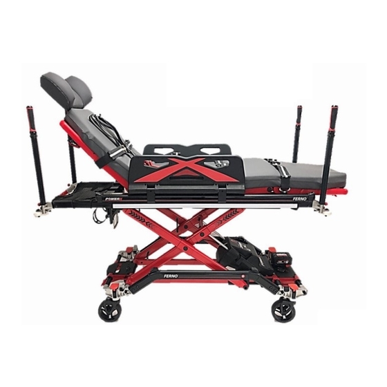
- Page 1 * Photo showing POWERX configured with optional SX cotsides Users’ Manual FERNO/MAN/0721/216-R22/UK Stock Code 2003-0148 Read this Manual and Retain for Future Reference...
- Page 2 ALL OTHER LOCATIONS For assistance or information, please contact your Ferno distributor. If you do not have a Ferno distributor, please contact your nearest Ferno Customer Services office. USA HEADQUARTERS Ferno-Washington, Inc., 70 Weil Way Wilmington, Ohio 45177-9371, U.S.A.
-
Page 3: Table Of Contents
6.31 Surface eXtending (SX) Cotside (option) _________ 24 6.32 Adjusting SX Cotside Position _________________ 25 6.33 SX Cotside Positioning for Patient Lateral Transfer _ 26 6.34 Using SX Cotsides for Bariatric Transfers _________ 26 6.35 Attachment of SX Cotsides ___________________ 27 FERNO/MAN/0721/216-R22/UK... -
Page 4: Safety Information
However, Ferno trolleys are designed to be compatible with trolley only as described in this manual. either the Ferno range of Two-Part locking devices or competitors equivalent locking devices, giving full compatibility and Improper parts and service can cause injury. Use only interchangeability across your vehicle fleet. -
Page 5: Safety And Instruction Labels
Safety and instruction labels place important information from The symbols defined below are used on the trolley and/or in this the user manual on the trolley. user manual. Ferno uses symbols recognised by the International Standards Organisation (ISO). Read and follow label instructions. Replace worn or damaged labels immediately. -
Page 6: Operator Skills And Training
WARNING Untrained operators can cause injury or be injured. Permit only trained personnel to operate the trolley. WARNING Improper use of the trolley can cause injury. Use the trolley only for the purpose described in this manual. FERNO/MAN/0721/216-R22/UK... -
Page 7: About Powerx
Fixed, detachable push poles at foot-end and head-end, 55 st 63 st utilising a hidden release lock LOAD LIMIT IN RAISED POSITION LOAD LIMIT IN LOWERED POSITION • Push poles stored within trolley frame when not being used, to prevent loss or abuse FERNO/MAN/0721/216-R22/UK... -
Page 8: Battery Information
To charge the battery, remove the battery pack from the dock on the trolley's battery dock. the foot end of the trolley by depressing the red release levers at each side of the battery and slide the battery pack towards you to remove. Battery release mechanism Removing battery pack FERNO/MAN/0721/216-R22/UK... -
Page 9: Battery Charge Indicator
Charging of batteries can be carried out at station using the mount is used. Both wall-mount and iNTRAXX-mountable supplied 240v mains battery charger, or in-vehicle using the brackets are available from Ferno for both types of charger. optional 12v battery charger. Important... -
Page 10: Powerx Operation
LED will also illuminate, confirming power is ON. of each shift. The LCD display shows the current number of lifts and the battery charge status. FERNO/MAN/0721/216-R22/UK... -
Page 11: Raising And Lowering The Trolley
Note that for safety purposes when POWERX is fixed into a the trolley, near the head-end. Ferno 2-part lock, the integrated interlock function within the trolley prevents the trolley from being raised up. Location of manual override handle at head-end... -
Page 12: Operating The Trolley Features
Then squeezing the outer lever, push down on the leg platform to bring it fully down. Once in lowest position, using centre lever to bend platform fully down so it touches the frame. Levers to adjust leg position FERNO/MAN/0721/216-R22/UK... -
Page 13: Detachable Headrest
Push frame whilst squeezing both levers patient's head size and clinical condition. It is made from the same foam and materials as the ABPR mattress Ensure telescoping frame is locked by pulling slightly towards you after shortening Adjustable winged Headrest FERNO/MAN/0721/216-R22/UK... -
Page 14: Shortening Trolley (Nov 20 Onwards)
1450 mm. However the head-end frame intentionally does not lock at this position and should only be used when manoeuvring through lifts/tight spaces. The trolley should not be loaded in a vehicle when fully shortened to 1450 mm. FERNO/MAN/0721/216-R22/UK... -
Page 15: Ab-Pr Mattress
The mattress is attached to the trolley top utilising a clinically- developed anti-bacterial AB-VELCRO®, making removal of mattress for cleaning both quick and easy, whilst maintaining infection control standards. Sidepad attached onto SX cotside Fixing straps on back of SX sidepad AB-VELCRO® fixing pads on AB-PR mattress FERNO/MAN/0721/216-R22/UK... -
Page 16: Wheel Brake
Disengaging wheel brake push forward and down 6.12 - Anti Static Wheel To prevent static build-up within the trolley whilst moving, POWERX is fitted with one anti-static wheel. Wheel brake disengaged, pedal raised Anti Static wheel Wheel brake engaged, pedal points down FERNO/MAN/0721/216-R22/UK... -
Page 17: Foot-Operated Directional Wheel Lock (Pre Nov 20)
Directional wheel lock pin drops when engaged and locks into to of wheel fork once trolley is moved forward FERNO/MAN/0721/216-R22/UK... -
Page 18: Side-Lighting (Option)
The siderail interface on POWERX is the same as is used on To change the default mode of lighting to use, press and hold the Ferno's iNX patient transportation system, meaning that all clip- white button for about 2 seconds until the lights flash red rapidly, on accessories are interchangeable between units and systems. -
Page 19: 3-Stage Iv Pole (Option)
Manual, reference 00271-AU-V01, which is risk that oil with oxygen under pressure can pose, in the available from Ferno. (unlikely) event of an incident and the O2 cylinder getting ruptured. FERNO/MAN/0721/216-R22/UK... -
Page 20: Head-End Storage Net (Option)
CEN complaint crash-tested bracket, such Storage net on head-end trolley frame as Ferno's IPTS iNTRAXX wall track and equipment bracket system. For more information on the head-end storage net please also refer to the Storage Net User Manual, reference 234-3590-01, which is available from Ferno. -
Page 21: Pacrac+ (Option)
PacRac+, attached using transported in the ambulance with medical equipment remained Ferno's CEN compliant iNTRAXX bracket system, or temporarily attached. Dynamically tested to 10G, PacRac+ is certified and strapped using the supplied straps and buckles. -
Page 22: Lateral Transfer With Pacrac
Push poles are then automatically locked in place once stored. To remove, lift the end-cap and pull out the pole, ensuring that fingers are kept away from the trolley frame. FERNO/MAN/0721/216-R22/UK... -
Page 23: Push Pole Locking (Pre-Nov 2020)
Pull towards end of trolley to unlock, then pull towards you to unfold Insert push pole until it Release by pulling out the Unfold fully until clicks in place locks into place locking pin located behind the push pole holder Side handles ready for use Release pin FERNO/MAN/0721/216-R22/UK... -
Page 24: Surface Extending (Sx) Cotside (Option)
SX cotsides in near-vertical position - (10 SX cotsides ratchet position 3 - (62.5 SX cotsides ratchet position 1 - (27.5 SX cotsides in near-horizontal position - (80 SX cotsides ratchet position 2 - (45 SX cotsides folded fully down FERNO/MAN/0721/216-R22/UK... -
Page 25: Adjusting Sx Cotside Position
A click will be heard when the cotside locks into place. Release lever and move SX cotside back up to required position Moving the SX cotside to the required position FERNO/MAN/0721/216-R22/UK... -
Page 26: Sx Cotside Positioning For Patient Lateral Transfer
Move the cotside fully down Fixing point of SX Surface Xtenders For more information on the SX ratcheting SX cotside fully down cotsides, please also refer to the SX Surface Xtenders User Manual, reference 00334-AU*UK, which is available from Ferno. FERNO/MAN/0721/216-R22/UK... -
Page 27: Attachment Of Sx Cotsides
Split Scoop kit has been dynamically crash tested and certified to EN 1789 when used with Ferno trolleys with a side interface rail, i.e. POWERX, iNX and Mondial. Load tested with 200 kg on each side of trolley with Scoop attached, to ensure same SWL of trolley is maintained when used with or without Split Scoop kit. -
Page 28: Attaching Split Scoop Extended Surface Kit
Position it as far towards the foot-end as possible on the siderail. Two halves of Scoop laid on top of fixing brackets Attaching fixing bracket to siderail interface FERNO/MAN/0721/216-R22/UK... - Page 29 Scoop. Recheck to ensure Scoop still positioned such that hand-hold holes are in line with locking arms on foot- end bracket Ensure Scoop fins are under the holding plates FERNO/MAN/0721/216-R22/UK...
- Page 30 Note that when using the Split-Scoop module the Scoop sides MUST be supported underneath when moving a patient on/off the trolley to ensure there is no imbalance of trolley and should always be carried out with the trolley in the lowest possible position. FERNO/MAN/0721/216-R22/UK...
-
Page 31: Preparing To Transport A Patient
BS EN 1789, the patient must be fully restrained at all times using the supplied 4-point chest harness and 2 leg straps or other Ferno- approved alternative patient harness system. 1. Before using the trolley the harness and both leg straps should be checked to ensure they are present, correctly attached and not damaged in any way. -
Page 32: Deploying 4-Point Harness And Chest/Leg Straps
(feed and pull). To loosen strap, pull the lower strap whilst feeding the strap above through the buckle. Buckle for adjustment of strap on shoulders & waist 4-point harness,chest strap and leg straps applied FERNO/MAN/0721/216-R22/UK... -
Page 33: Unfastening 4-Point Harness And Straps
The harness system utilises a tri-glide system that ensures that the ends of harness do not Squeeze the two bronze clips to open the leg strap hang below the trolley, an extra safety feature buckles to reduce the straps from catching and getting dirty FERNO/MAN/0721/216-R22/UK... -
Page 34: Deploying Cross-Strap Harness
Take one of the Crossover straps (red or blue) and cross it over Crash tested and CEN complaint as with all Ferno trolley patient the patient's body, clipping it into the buckle with corresponding harness systems, the Cross-Strap system for POWERX offers same-coloured strap on the other side of the trolley. -
Page 35: Unfastening Cross-Strap Harness
Next attach the leg strap, again ensuring that it is tightened If the strap has been adjusted longer, it can be clipped into the sufficiently. buckle on that side to avoid it hanging down to the floor FERNO/MAN/0721/216-R22/UK... -
Page 36: Lateral Transfer Of Patients To Chair
With chair and trolley at similar height, this makes transfer from into place. chair and trolley minimal risk, as there is minimal incline when moving the patient across the transfer board Lift firmly until tang clicks in the stud FERNO/MAN/0721/216-R22/UK... - Page 37 Ensure the tang is indeed attached. Do this also on the other side of the trolley. FERNO/MAN/0721/216-R22/UK...
-
Page 38: Attaching 3Rd Party Child Harness (Acr Etc.)
POWERX was not designed or tested for the attachment of third there is no movement. party harnesses. However there is available from Ferno a set of 4 fixing tangs to facilitate attachment of other child harnesses, such as the ACR harness, where the upper fixing straps do not... - Page 39 After the ACR has been used, disconnect the tangs from each attachment point on the trolley. Note that the tangs can be kept connected to the ACR fixing straps whilst the harness is not in use and being stored. FERNO/MAN/0721/216-R22/UK...
-
Page 40: Strap Attachment Points (4-Point Harness)
1. Attachment point for ACR lower fixing straps 2. Attachment point for buckle for crossover strap 3. Attachment point for bottom end of crossover strap. End of Crossover strap also incorporates loop for attaching Pedimate. 4. Not used 5. Attachment point for lower-leg strap FERNO/MAN/0721/216-R22/UK... -
Page 41: Preparing To Move The Trolley
Secure the trolley into the Ferno 2 part-lock for transportation. The trolley is recommended to be operated by at least two people at all times. -
Page 42: Unloading A Trolley From A Vehicle With A Tail-Lift
All have been dynamically crash-tested to BS EN 1789 and Operate the tail-lift as per the manufactures instructions. CEN certified when used in conjunction with Ferno UK's range of ambulance trolleys, Falcon, Pegasus, Megasus, Harrier and Lower the tail-lift to the ground and move trolley forward POWERX. -
Page 43: Locking Devices
Ferno SlideLock (150) Ferno SlideLock is a 2-position ambulance trolley lock system, allowing the position of the trolley lock to be moved from side to centre (C to B) quickly and easily, without the need to remove the... -
Page 44: Slidelock
Greasing of the rail will only attract build-up of dirt and debris. Further detains on cleaning and maintenance are included in the SlideLock Installation and Maintenance guide (0859-0006 & 0859- 0003) Removal of cover plates for cleaning linear slide rail and enclosure FERNO/MAN/0721/216-R22/UK... -
Page 45: Maintenance
Ferno recommends you inspect the trolley for damage as the manufacturer’s guidelines, and that the equipment is you clean and disinfect it. See note regarding disinfectants to use. -
Page 46: Lubricating The Trolley
12.1 - Accessories for POWERX 10.5 - Lubrication of parts Ferno offers a full line of accessories and products for use with Disinfect and clean the trolley before applying lubricant. Use POWERX, many of which are outlined in this user manual. -
Page 47: Inspection
Check that the trolley cotsides raise, lower and lock in position. Check that the ambulance has a properly installed, approved locking device and that the trolley locks in securely. ● Check the operation of the push/pull handles and push poles ● FERNO/MAN/0721/216-R22/UK... - Page 48 FERNO/MAN/0721/216-R22/UK...
-
Page 49: Servicing
14 - SERVICING SCHEDULE It is recommended in addition to the regular inspection and cleaning interventions that Ferno POWERX is serviced at least once every 12 months. Below is a service schedule sheet where servicing dates and activities can be recorded. Ferno UK offers a range of cost-effective servicing programmes, helping to keep your equipment in good condition and keeping whole life time costs to a minimum. - Page 50 FERNO/MAN/0721/216-R22/UK...
Need help?
Do you have a question about the POWER X SN-POW1001 and is the answer not in the manual?
Questions and answers