Table of Contents

Related Manuals for SCHUNK WBL 22.03


Summary of Contents for SCHUNK WBL 22.03
- Page 1 Pantograph Type: WBL 22.03 Dwg. -No.: SB-035320 Spare Part No.: 10864159 SB-038485_RS_Blatt1 Pneumatic Control Dwg. -No.: 1-V15.15750 / 1-V15.16074 Spare Part No.: 10601221 / 10609604 Description Maintenance and Operating Instructions...
- Page 2 First Edition 7.2.2019 / MSO 11.2.2019 /FRB Copyright by Schunk Bahn- und Industrietechnik GmbH Salzburg. All rights reserved. This publication may not be reproduced, stored in a retrieval system, translated into another language, or transmitted in whole or in part, in any form or by any means, electronic, mechanical, photocopying, recording, or otherwise, without the prior written permission of Schunk Bahn- und Industrietechnik GmbH.
-
Page 3: Table Of Contents
Schunk Bahn- und Industrietechnik GmbH TABLE OF CONTENTS Introduction .................. 9 General Information ..................9 Usage Instructions .................... 9 Safety Instructions ..............10 Classification of Safety Instructions ..............10 Possible Risk Types and Risk Sources ............11 Possible Consequences of Risks ..............11 Care of the Operator .................. - Page 4 Schunk Bahn- und Industrietechnik GmbH Storage..................38 Storage inside Transportation Package ............38 Storage outside Transportation Package ............38 Transportation ................39 Assembly ..................41 Attachment to Vehicle Roof ................41 Attachment of High Voltage Connection ............43 Attachment of Pneumatic Equipment .............. 44 Start Up ..................
- Page 5 Schunk Bahn- und Industrietechnik GmbH Replacement of Wear Parts ................69 Cable with Terminals ................69 Parallel Guide Bar ................... 71 Pan Head ....................72 Shock Absorber ..................74 Shunts ....................75 Troubleshooting ................. 81 Safety Instructions ..................81 Trouble List ..................... 82 Disassembly ................
- Page 6 Schunk Bahn- und Industrietechnik GmbH Spare Parts ................109 General Information ..................109 Pantograph ....................110 Base Frame ..................115 Lower Frame ..................116 Upper Frame ..................118 Air Bellow Drive ..................119 Cable with Terminals ................121 Coupling Rod ..................122 Parallel Guide ..................
- Page 7 Schunk Bahn- und Industrietechnik GmbH ILLUSTRATIONS Illustration 1: Components ..................19 Illustration 2: Base frame ................... 20 Illustration 3: Lower frame ..................21 Illustration 4: Upper frame ..................22 Illustration 5: Air bellow drive ..................23 Illustration 6: Valve unit ADD ..................24 Illustration 7: Lock cock OPEN - ADD ACTIVATED ..........
- Page 8 Schunk Bahn- und Industrietechnik GmbH Illustration 33: Mounting angle ................... 77 Illustration 34: Shunts between base frame and coupling rod ........78 Illustration 35: Mounting angle ................... 78 Illustration 36: Shunts between lower frame and upper frame ........79 Illustration 37: Mounting angle ................... 79 Illustration 38: Shunts between upper frame and rocker box / sliding strip ....
-
Page 9: Introduction
Schunk Bahn- und Industrietechnik GmbH Introduction Introduction General Information The main objective was to produce a weight as light as possible and simple in structure, and thus low-maintenance pantograph. With these criteria was to achieve an equally good contact behavior, even in the simplest driving lines connected to the maximum operating safety. -
Page 10: Safety Instructions
Schunk Bahn- und Industrietechnik GmbH Safety Instructions Safety Instructions Classification of Safety Instructions S I G N A L W O R D Warning sign Type and source of danger Possible consequences for individuals, pantograph, tools and work piece Procedure to avoid the danger... -
Page 11: Possible Risk Types And Risk Sources
Schunk Bahn- und Industrietechnik GmbH Safety Instructions Possible Risk Types and Risk Sources • Unsecured shearing and crushing. • High voltage (catenary). • Falling from high altitude. • Injuries due to falling items. Possible Consequences of Risks • Death or injuries (squeezing, amputation, etc.) of involved and not-involved persons. -
Page 12: Care Of The Operator
Schunk Bahn- und Industrietechnik GmbH Safety Instructions Care of the Operator W A R N I N G Untrained staff operating Death injuries, damage due to improper work. • Only QUALIFIED and EXPERIENCED staff is allowed to perform operation, repairs, maintenance and other work. -
Page 13: Intended Use
Schunk Bahn- und Industrietechnik GmbH Safety Instructions Intended Use Your pantograph is exclusively used for collecting and carrying current for electric vehicles using a catenary. The current from the overhead line is passed to the actuator by the vehicle. The pantograph is mounted on the vehicle roof, and it is electrically insulated by insulators. -
Page 14: Not-Intended Use
Schunk Bahn- und Industrietechnik GmbH Safety Instructions Not-intended Use The operating and maintenance staff is required to pay attention to proper use. Safety devices may never be deactivated or bypassed. Maintenance instructions have to be followed. D A N G E R... -
Page 15: General Safety Instructions
Schunk Bahn- und Industrietechnik GmbH Safety Instructions General Safety Instructions D A N G E R High voltage while operation of pantograph Death, injuries, burn-up No person is allowed around the pantograph during operation. Electrical current in Catenary Death, burn-up Catenary –... -
Page 16: Technical Data
Schunk Bahn- und Industrietechnik GmbH Technical Data Technical Data Standard ....................IEC 60494-1/2 Static contact force ..................80 ± 5 N Rated current ...................... 400 A Nominal voltage ................25 kV AC (50 Hz) Resting position ..................585 ±10 mm Insulating distance resting pos. - Page 17 Schunk Bahn- und Industrietechnik GmbH Technical Data Automatic dropping device With air-monitored sliding strips Air bellow drive Compressed air connection........High voltage insulation hose Compressed air supply ..........min. 5 bar – max. 10 bar Dry and oil-free air (insulating characteristics) Compressed air acc.
-
Page 18: Pantograph Components
Schunk Bahn- und Industrietechnik GmbH Pantograph Components Pantograph Components General Information Main features of the Pantograph are: • function-oriented design • minimum maintenance • excellent dynamic contact behavior • maximum operating safety This is mainly achieved through: • Proven bearing techniques •... -
Page 19: Pantograph
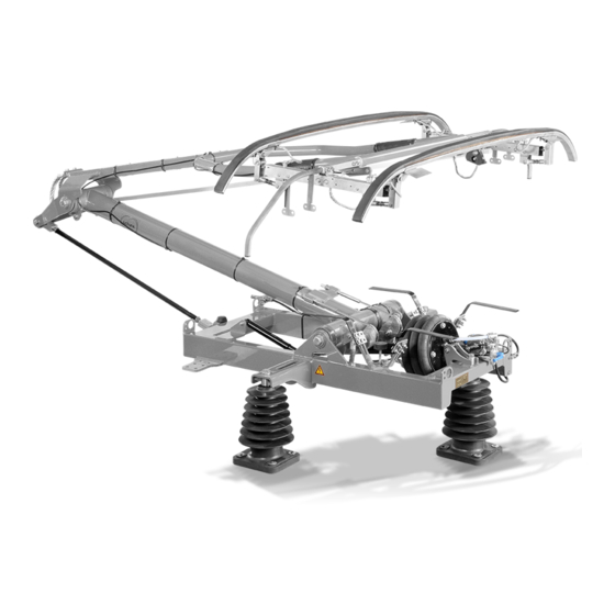
Schunk Bahn- und Industrietechnik GmbH Pantograph Components Pantograph SB-038485_RS_Blatt2 Illustration 1: Components Base frame compl. Lower frame Upper frame compl. Air bellow drive Valve unit ADD Coupling rod Parallel guide bar compl. Pan head Shock absorber Cable with terminals Overreach detection Insulator compl. -
Page 20: Base Frame
Schunk Bahn- und Industrietechnik GmbH Pantograph Components Base Frame The welded structure of the base frame is the basis of the pantograph. The component is coated for protection of environmental influences. The base frame is mechanically attached to the vehicle roof with insulators. The current is led from catenary to vehicle by the current connection at the base frame and the cabling from the vehicle. -
Page 21: Lower Frame
Schunk Bahn- und Industrietechnik GmbH Pantograph Components Lower Frame The lower frame is a welded structure which is rotary mounted to the base frame. The component is coated for protection of environmental influences. The cams assure that the static contact force is constantly over the whole working range of the pantograph. -
Page 22: Upper Frame
Schunk Bahn- und Industrietechnik GmbH Pantograph Components Upper Frame The upper frame is a welded structure made of steel tubes. The component is coated for protection of environmental influences. SB-038688_RS_Blatt1 Illustration 4: Upper frame All components of the Upper Frame are listed in the Spare Parts – List (... -
Page 23: Air Bellow Drive
Schunk Bahn- und Industrietechnik GmbH Pantograph Components Air Bellow Drive The pantograph is raised with the air bellow drive. The air bellow drive is mounted between base frame and lower frame. The force of the bellow is transmitted by cables which are running in cams. The air bellow drive is connected with the valve unit ADD with a compressed air hose. -
Page 24: Valve Unit Add
Schunk Bahn- und Industrietechnik GmbH Pantograph Components Valve Unit ADD The valve unit ADD (automatic dropping device) is used for monitoring the sliding strips to minimize damage of catenary and pantograph due to damaged sliding strips. If a sliding strip is damaged, a control pipe is opened and compressed air is releasing. -
Page 25: Illustration 7: Lock Cock Open - Add Activated
Schunk Bahn- und Industrietechnik GmbH Pantograph Components ADD Activated The valve unit ADD is in ACTIVATED state when the pantograph is delivered. Therefore, monitoring of the sliding strips is enabled. D A N G E R Pantograph raised PNEUMATICALLY. Valve unit ADD responds, pantograph lowers. -
Page 26: Illustration 8: Lock Cock Closed - Add Deactivated
Schunk Bahn- und Industrietechnik GmbH Pantograph Components ADD Deactivated The valve unit ADD is in ACTIVATED state when the pantograph is delivered. Therefore, monitoring of the sliding strips is enabled. Activate ADD ( Chapter #4.2.5.1). A T T E N T I O N ADD ACTIVATED when performing leaking test. -
Page 27: Coupling Rod
Schunk Bahn- und Industrietechnik GmbH Pantograph Components Coupling Rod The coupling rod consists of a connection tube made of a stainless-steel round-tube and two bearing houses (equipped with grooved ball bearings) with left-hand-thread and right-hand-thread. By turning of the connection tube, the geometry of the pantograph will be adjusted and fine-tuned. -
Page 28: Parallel Guide
Schunk Bahn- und Industrietechnik GmbH Pantograph Components Parallel Guide The parallel guide bar prevents the pan head from distorting, while the pantograph is raised or lowered. The turning capacity of the pan head is adjusted by screwing-in and screwing-out the rod end of the parallel guide bar. This achieves equal wear on both sliding strips. -
Page 29: Pan Head
Schunk Bahn- und Industrietechnik GmbH Pantograph Components Pan Head The Pan Head is mounted onto a shaft, which in turn is located inside the cross tube of the upper frame. Leaf springs are used for the suspension of the sliding strips. The pan head springs (leaf springs) are affixed in the rocker boxes and they carry the sliding strips. -
Page 30: Shock Absorber
Schunk Bahn- und Industrietechnik GmbH Pantograph Components Shock absorber The shock absorber between lower frame and base frame compensates vibrations of the pantograph. The stages of compression and tension are designed to assure best contact behavior between sliding strips and catenary. -
Page 31: Cable With Terminals
Schunk Bahn- und Industrietechnik GmbH Pantograph Components Cable with Terminals The cables with terminals consist of round braids with secured terminals at both ends. The cables are secured against twisting at these secured terminals when detaching / attaching cables. The cables with terminals are guided by the cable guide of the air bellow drive and at the cams of the lower frame. -
Page 32: Overreach Detection
Schunk Bahn- und Industrietechnik GmbH Pantograph Components Overreach detection The overreach detection is used to detect a lifting height. Function: The overreach detection is supplied with compressed air from the air bellow drive. When the lifting height is reached, the stop switches the 3/2-way valve and compressed air flows to the pressure safeguard. -
Page 33: Insulator
Schunk Bahn- und Industrietechnik GmbH Pantograph Components Insulator The pantograph is mounted on supporting insulators. The supporting insulators provide the electrical insulation between the live pantograph and the roof of the vehicle. SB-038777_RS_Blatt1 SB-038483-EN.docx Datum: 13.02.2018 33 / 147 SAP.Nr.10901359... -
Page 34: Shunts
Schunk Bahn- und Industrietechnik GmbH Pantograph Components Shunts All bearing locations are bypassed with shunts. This prevents current from flowing through the bearings. The shunts are composed of a copper wire which is provided on both sides with a tubular lug (1). -
Page 35: Type Tag
Schunk Bahn- und Industrietechnik GmbH Pantograph Components Type Tag The type tag is located on the base frame. For questions about your pantograph please indicate TYPE (4), DWG NO (5) and REV.NO (6). SB-028704_RS.idw - Blatt 1 - Rev. - Illustration 15: Type tag SERIAL NO. -
Page 36: Pneumatic Control
Schunk Bahn- und Industrietechnik GmbH Pantograph Components Pneumatic Control The pneumatic plan can be found Appendix A. The main functions of the pneumatic control are: • Control of static contact force • Control of raising and lowering time •... -
Page 37: Packaging
Schunk Bahn- und Industrietechnik GmbH Packaging Packaging A T T E N T I O N Improper packaging Damages • The pan head must be UPSIDE. • All components must be INSIDE the packaging. • Open components (e. g. sockets, hoses) must be protected against ingress of moisture. -
Page 38: Storage
Schunk Bahn- und Industrietechnik GmbH Storage Storage A T T E N T I O N Improper storage Damages • Always store the pantograph with the proper side up, the pan head has to be upside. • Never store other components onto the pantograph or its package. -
Page 39: Transportation
Schunk Bahn- und Industrietechnik GmbH Transportation Transportation D A N G E R Unsecured transportation Death, injuries and / or damage of pantograph Transportation of pantograph only when it is LOWERED. Fix upper frame to base frame during transportation (e. g. with belt). -
Page 40: Illustration 16: Lifting Eye Nuts
Schunk Bahn- und Industrietechnik GmbH Transportation SB-038935_RS_Blatt1 Illustration 16: Lifting eye nuts Transportation and lifting of pantograph outside the package ONLY at the marked lifting eye nuts. SB-038483-EN.docx Datum: 13.02.2018 40 / 147 SAP.Nr.10901359 Index: -... -
Page 41: Assembly
Schunk Bahn- und Industrietechnik GmbH Assembly Assembly Attachment to Vehicle Roof The base frame must be mounted tension free onto the vehicle roof. The base tube of the lower frame must be horizontal. If needed washers may be placed underneath the insulators to act as shims. -
Page 42: Illustration 17: Example: Base Tube Of Lower Frame
Schunk Bahn- und Industrietechnik GmbH Assembly The base tube of the lower frame must be horizontal. If necessary, washers have to be placed underneath the insulators, to act as shims. SB-035494_RS.idw - Blatt 4 - Rev.- Illustration 17: EXAMPLE: Base tube of lower frame 8. -
Page 43: Attachment Of High Voltage Connection
Schunk Bahn- und Industrietechnik GmbH Assembly Attachment of High Voltage Connection D A N G E R Dirty, coated and / or ungreased shunt connections Inaccurate current flow, injuries, damages Clean and grease shunt connections and connection boards. SB-038935_RS_Blatt2 Illustration 18: High voltage connection The High Voltage Connection has to be mounted at the connection boards (1), which is attached to the base frame. -
Page 44: Attachment Of Pneumatic Equipment
Schunk Bahn- und Industrietechnik GmbH Assembly Attachment of Pneumatic Equipment The compressed air supply is connected to the pantograph with insulating hoses. After assembly, the air connections have to be checked for tightness (e. g. with a leak detection spray Chapter #11.3.1). -
Page 45: Start Up
Schunk Bahn- und Industrietechnik GmbH Start Up Start Up Safety Instructions D A N G E R High voltage while operation of pantograph Death, injuries, burn-up No person is allowed around the pantograph during operation. Tools and / or items reducing insulating distance Current flashover, injuries, burn-up •... -
Page 46: Check List
Schunk Bahn- und Industrietechnik GmbH Start Up Check List Before start up check the following: 1. Check if insulating distance according to technical data ( Chapter #3). 2. Assure that the screw connection of the high voltage connection is properly fastened and well-greased (... -
Page 47: Operation
Schunk Bahn- und Industrietechnik GmbH Operation Operation D A N G E R Blocked or invalid safety units Injuries Never block safety units or make them invalid. Manual unavailable Death, injuries, damages due to lack of information Read manual before start-up. -
Page 48: Maintenance
Schunk Bahn- und Industrietechnik GmbH Maintenance Maintenance Safety Instructions D A N G E R Electrical current in Catenary Death, burn-up Catenary – Switch off and ground current. Secure against reset. Unsecured squeezing points at raised pantograph Squeezing, Amputation Lower pantograph before cleaning, maintenance, repairs or other work. -
Page 49: Maintenance Intervals
Schunk Bahn- und Industrietechnik GmbH Maintenance Maintenance Intervals The single arm pantograph requires a minimum of maintenance. The required maintenance is influenced by the environmental and operational conditions, so the operator has accordingly to adapt. Interval 1 – Every Week (max. 7000 km) •... -
Page 50: Interval 3 - Every Year (Max. 250.000 Km)
Schunk Bahn- und Industrietechnik GmbH Maintenance Interval 3 – Every Year (max. 250.000 km) • Checkup Static contact force ( Chapter #14.8). Raising and lowering time acc. to technical data ( Chapter #3). Screw connections for proper torque and tight fit ( Chapter #11.3.2). -
Page 51: Interval 4 - Every 2 Years (Max. 500.000 Km)
Replacement of all shunts ( Chapter #11.5.5). Interval 5 – Every 8 Years (max. 2.000.000 km) • Detach pantograph and pneumatic control from vehicle roof. • Overhaul at Schunk Bahn- und Industrietechnik GmbH. • Attach pantograph to vehicle roof. SB-038483-EN.docx Datum: 13.02.2018 51 / 147 SAP.Nr.10901359... -
Page 52: Maintenance Instructions
W A R N I N G Injuries due to lack of protective clothing Skin irritation, burn of respiratory system When handling with consumables wear safety gloves and respiratory protection. Schunk Bahn- und Industrietechnik recommend the following consumables: Description Product Manufacturer... -
Page 53: Screw Connections
Schunk Bahn- und Industrietechnik GmbH Maintenance Screw Connections D A N G E R Attachment of unsecured and / or used screw connections Loosened screw connections, damages Hex nuts according ISO 10511 and conical spring washers according BN 208010-8 must be replaced by new ones after dismounting. - Page 54 Schunk Bahn- und Industrietechnik GmbH Maintenance Torque for Screw Connections A2-70 Torques are valid by using an assembly lubricant. Categorization of the screw connection according to DIN 25201-2-B Fastening torque Fastening torque Thread [mm] Thread [mm] [Nm] [Nm] 30,0 70,0...
-
Page 55: Greasing
Schunk Bahn- und Industrietechnik GmbH Maintenance Greasing Consumables Chapter #11.3.1 W A R N I N G Injuries due to lack of safety equipment. Skin irritation, burn of respiratory system When handling with consumables wear safety gloves and respiratory protection. - Page 56 Schunk Bahn- und Industrietechnik GmbH Maintenance ASSEMBLY LUBRICANT All screw connections at outer thread and at contact surface of the tightened component (nut-surface or head-surface of screw). THREAD SEALANT All pneumatic screw connections which are not self-locking. SB-038483-EN.docx Datum: 13.02.2018 56 / 147 SAP.Nr.10901359...
-
Page 57: Checkup
Schunk Bahn- und Industrietechnik GmbH Maintenance Checkup Cable with Terminals The cable with terminals has to be checked for breaks of wires and braids. The cable with terminals has to be replaced: • within the scheduled maintenance intervals ( Chapter #11.2). -
Page 58: Parallel Guide
Schunk Bahn- und Industrietechnik GmbH Maintenance Parallel Guide Rod End The rod end of the parallel guide has to be checked for deformation. Procedure: 1. Check rod end for deformation. 2. Replace damaged rod end ( Chapter #11.5.2). SB-038483-EN.docx Datum: 13.02.2018... -
Page 59: Pan Head
Schunk Bahn- und Industrietechnik GmbH Maintenance Pan Head Sliding Strip D A N G E R Dirty, coated and / or ungreased contact surface Incorrect current flow, injuries, damages Clean and grease contact surfaces. Pantograph raised PNEUMATICALLY. Valve unit ADD responds, pantograph lowers. -
Page 60: Illustration 21: Minimum Thickness
Schunk Bahn- und Industrietechnik GmbH Maintenance Sliding strips must be replaced: • Damage (break) • Minimum thickness acc. to illustration (wear). Illustration 21: Minimum thickness Replace damaged components ( Chapter #11.5.3). After replacement of sliding strips: • Check static contact force ( Chapter #14.8). - Page 61 Schunk Bahn- und Industrietechnik GmbH Maintenance Pan Head Suspension The pan head suspension (leaf springs and parallel guide of rocker boxes) must be checked for function, easy motion, deformation and corrosion. Procedure: Raise and fix pantograph at medium working height.
-
Page 62: Shock Absorber
Schunk Bahn- und Industrietechnik GmbH Maintenance Shock Absorber The shock absorber must be checked for leakage. Leaking Test: 1. Detach shock absorber ( Chapter #11.5.4). 2. Extend shock absorber to maximum length. 3. Hold shock absorber vertically. 17293ipn_Blatt1 Illustration 22: Checkup of shock absorber 4. -
Page 63: Valve Unit Add
Schunk Bahn- und Industrietechnik GmbH Maintenance Valve Unit ADD Checkup of Function The valve unit ADD must be checked for correct function. Procedure: 1. Lower pantograph pneumatically. NEVER attach belt at parts of the pan head. 2. Raise pantograph pneumatically and hold it by hand just over resting position. -
Page 64: Illustration 24: Open Test Valve
Schunk Bahn- und Industrietechnik GmbH Maintenance b. Release belt: The pantograph stays in resting position. c. Shut – off compressed air supply. d. Fix belt between base frame and upper frame. SB-036450_RS.idw - Blatt 4 - Rev.- Illustration 24: OPEN test valve 6. -
Page 65: Illustration 26: Lock Test Valve
Schunk Bahn- und Industrietechnik GmbH Maintenance 7. LOCK Test Valve: a. Detach nut (1). b. Detach lever (2) and turn it 180° degrees. c. Attach lever (2) to the valve unit ADD and fix it with the nut (1). 8. Switch – on compressed air supply. -
Page 66: Shunts
Schunk Bahn- und Industrietechnik GmbH Maintenance Shunts Shunts must be checked for damage. Shunts must be replaced within the scheduled maintenance intervals Chapter #11.2 Damaged shunts must be replaced. Current connections and tubular lugs of shunts must be free from coating, blank and clean. -
Page 67: Leak Detection
Schunk Bahn- und Industrietechnik GmbH Maintenance Leak Detection All compressed air connections must be checked for leakage (e.g. with a leak – detection spray ( Chapter #11.3.1). Procedure: 1. Check air connection from vehicle to valve unit ADD. 2. Check air connection from vehicle to pneumatic control. -
Page 68: Overreach Detection
Schunk Bahn- und Industrietechnik GmbH Maintenance Overreach detection The lifting height limitation must be checked annually for function and damage. • Lower the pantograph. • Activate lifting height limitation. • Lift the pantograph pneumatically. • Lift the pantograph only up to the specified height (Chapter #3). -
Page 69: Replacement Of Wear Parts
Schunk Bahn- und Industrietechnik GmbH Maintenance Replacement of Wear Parts Cable with Terminals SB-026314_RS.idw - Blatt 5 - Rev. - Illustration 27: Example Replace cable with terminals Detachment: NEVER raise pantograph pneumatically when replacing cable with terminals. 1. Assure that compressed air supply is shut-off. - Page 70 Schunk Bahn- und Industrietechnik GmbH Maintenance Attachment: 1. Grease cable with terminals at the contact surfaces to lower frame (4), cam (3) and cable guide (5) ( Chapter #11.3.3). 2. Place check nuts and washer (3) to cable with terminals (1).
-
Page 71: Parallel Guide Bar
Schunk Bahn- und Industrietechnik GmbH Maintenance Parallel Guide Bar Rod End SB-035907_RS.idw - Blatt 1 - Rev. - Illustration 28: Replace rod end Detachment: 1. Loosen check nut (2). 2. Screw-out rod end (1). Attachment: 1. Grease rod end and check nut (2) ( Chapter #11.3.3). -
Page 72: Pan Head
Schunk Bahn- und Industrietechnik GmbH Maintenance Pan Head Sliding Strip D A N G E R Pantograph raised pneumatically at replacement of sliding strips Valve unit ADD responds, pantograph lowers NEVER raise pantograph pneumatically when replacing sliding strips. After replacement of sliding strips: Check if all air pressure hoses are connected properly to the sliding strips. - Page 73 Schunk Bahn- und Industrietechnik GmbH Maintenance Detachment: NEVER raise pantograph pneumatically when replacing sliding strips. 1. Assure that compressed air supply is SHUT-OFF. 2. Detach air pressure hose (2) from sliding strip and secure it against ingress of dirt (e. g. by taping).
-
Page 74: Shock Absorber
Schunk Bahn- und Industrietechnik GmbH Maintenance Shock Absorber SB-026341_RS.idw - Blatt 1 - Rev. A Illustration 30: EXAMPLE: Replace damper Detachment: 1. Detach screw set (2) from lower frame. 2. Detach screw set (3) from base frame. 3. Detach shock absorber (1) ... -
Page 75: Shunts
Schunk Bahn- und Industrietechnik GmbH Maintenance Shunts 17189ipn_Blatt1 Illustration 31: Replacement of shunts Before detaching shunts take a close look, how the shunts are attached (e. g. taking a photo, measuring a certain angle, etc.). Attachment: Shunt connections (2) and tubular lugs of shunts (1) must be uncoated, blank and clean. - Page 76 Schunk Bahn- und Industrietechnik GmbH Maintenance 6. Adjust shunts to following criteria: a. Shunts may never TOUCH EACH OTHER. b. Shunts may never TOUCH OTHER COMPONENTS of the pantograph. c. Shunts may never BE TENSIONED. d. Shunts MUST always HANG LOOSELY.
-
Page 77: Illustration 32: Shunts Between Base Frame And Lower Frame
Schunk Bahn- und Industrietechnik GmbH Maintenance Base Frame to Lower Frame SB-038205_RS.idw - Blatt 11 Illustration 32: Shunts between base frame and lower frame SB-038205_RS.idw - Blatt 12 Illustration 33: Mounting angle SB-038483-EN.docx Datum: 13.02.2018 77 / 147 SAP.Nr.10901359 Index: -... -
Page 78: Illustration 34: Shunts Between Base Frame And Coupling Rod
Schunk Bahn- und Industrietechnik GmbH Maintenance Base Frame to Coupling Rod SB-038935_RS_Blatt6 Illustration 34: Shunts between base frame and coupling rod SB-035449_RS.idw - Blatt 7 - Rev.- Illustration 35: Mounting angle SB-038483-EN.docx Datum: 13.02.2018 78 / 147 SAP.Nr.10901359 Index: -... -
Page 79: Illustration 36: Shunts Between Lower Frame And Upper Frame
Schunk Bahn- und Industrietechnik GmbH Maintenance Upper Frame to Lower Frame SB-038205_RS.idw - Blatt 17 Illustration 36: Shunts between lower frame and upper frame SB-038205_RS.idw - Blatt 18 Illustration 37: Mounting angle SB-038483-EN.docx Datum: 13.02.2018 79 / 147 SAP.Nr.10901359 Index: -... -
Page 80: Illustration 38: Shunts Between Upper Frame And Rocker Box / Sliding Strip
Schunk Bahn- und Industrietechnik GmbH Maintenance Upper Frame to Rocker Box / Sliding Strip SB-038935_RS_Blatt4 Illustration 38: Shunts between upper frame and rocker box / sliding strip SB-038483-EN.docx Datum: 13.02.2018 80 / 147 SAP.Nr.10901359 Index: -... -
Page 81: Troubleshooting
Schunk Bahn- und Industrietechnik GmbH Troubleshooting Troubleshooting Safety Instructions D A N G E R Electrical current in Catenary Death, burn-up Catenary – Switch off and ground current. Secure against reset. Unsecured squeezing points at raised pantograph Squeezing, Amputation Lower pantograph before cleaning, maintenance, repairs or other work. -
Page 82: Trouble List
Schunk Bahn- und Industrietechnik GmbH Troubleshooting Trouble List DEFECT REASON(S) CORRECTION CHECKUP: Static contact force Chapter #14.8 Static contact force is poorly adjusted. ADJUSTMENT: Static contact force Chapter #14.9 CHECKUP: Air bellow drive for damage Air bellow drive defective. - Page 83 Schunk Bahn- und Industrietechnik GmbH Troubleshooting DEFECT REASON(S) CORRECTION CHECKUP: Static contact force Chapter #14.8 Static contact force is poorly adjusted. ADJUSTMENT: Static contact force Chapter #14.9 CHECKUP: Static contact force ( Chapter #14.8) CHECKUP: Inner friction of...
- Page 84 Schunk Bahn- und Industrietechnik GmbH Troubleshooting DEFECT REASON(S) CORRECTION FASTEN: Loosened screw Loosened screw connections connections. Chapter #11.3.2 CHECKUP: Leaking test Chapter #11.4.7 Air bellow drive Leaking air line. defective. REPLACEMENT: Air line Chapter #4.2.5 REPLACEMENT: Bellow cylinder leaking.
-
Page 85: Disassembly
Schunk Bahn- und Industrietechnik GmbH Disassembly Disassembly General Information Prior to disassembling pantograph components, please study the spare parts catalogue and inform yourself about the relationship of the individual component parts ( Chapter #17). Safety Instructions D A N G E R... -
Page 86: Detachment From Vehicle
Schunk Bahn- und Industrietechnik GmbH Disassembly Detachment from Vehicle Electrical current in catenary. From inside vehicle: 1. Switch off current in catenary. 2. Secure against reset. 3. Ground catenary. 4. Lower pantograph to resting position. Unexpected pressure of pneumatic system. -
Page 87: Adjustment Procedures
Schunk Bahn- und Industrietechnik GmbH Adjustment Procedures Adjustment Procedures Safety Instructions D A N G E R Electrical current in Catenary Death, burn-up Catenary – Switch off and ground current. Secure against reset. Unsecured squeezing points at raised pantograph Squeezing, Amputation Lower pantograph before cleaning, maintenance, repairs or other work. -
Page 88: General Information
Schunk Bahn- und Industrietechnik GmbH Adjustment Procedures General Information Detach shock absorber while performing adjustment procedures ( Chapter #11.5.4). Otherwise results will be falsified. Each pantograph has been properly adjusted by the manufacturer. After repair, replacement of components or disassembly the following adjustment procedures have to be executed: 1. -
Page 89: Checkup Of Resting Position
Schunk Bahn- und Industrietechnik GmbH Adjustment Procedures Checkup of Resting Position Procedure: 1. Lower pantograph. 2. Attach spirit level over the whole length of the pantograph. 3. Adjust spirit level at highest point of the pantograph. 4. Measurement of resting position. -
Page 90: Adjustment Of Resting Position
Schunk Bahn- und Industrietechnik GmbH Adjustment Procedures Adjustment of Resting Position Resting position is adjusted according to the value of technical data ( Chapter #3). SB-035494_RS.idw - Blatt 5 - Rev.- Illustration 39: EXAMPLE: Adjustment of resting position (h Procedure: ): ... - Page 91 Schunk Bahn- und Industrietechnik GmbH Adjustment Procedures Change Length of Coupling Rod: 1. Loosen check nuts (6). 2. Lengthen coupling rod: a. Turn rod (7) until lower frame (5) loses contact to the limit stop (4). 3. Shorten coupling rod: a.
-
Page 92: Adjustment Of Support Springs
Schunk Bahn- und Industrietechnik GmbH Adjustment Procedures Adjustment of Support Springs SB-035494_RS.idw - Blatt 6 - Rev.- Illustration 40: EXAMPLE: Adjust support springs Procedure: 1. Loosen screw connection (2). 2. Adjust support springs (1) by sliding: Both sliding strips (3) must rest on support springs (1) horizontal and at same height. -
Page 93: Adjustment Of Air Bellow Drive
Schunk Bahn- und Industrietechnik GmbH Adjustment Procedures Adjustment of Air Bellow Drive 5mm 17132_Blatt 0 Illustration 41: Adjustment of air bellow drive Procedure: Secure cable against twisting ONLY at the secured ends of the cable. 1. Secure cable (1) against twisting. -
Page 94: Adjustment Of Blow-Off Valve
Schunk Bahn- und Industrietechnik GmbH Adjustment Procedures Adjustment of Blow-Off Valve The pressure limiting valve (PLV1 Chapter #Appendix A) is properly adjusted by the manufacturer. The blow-off valve must be adjusted if there is a change of operating pressure or if the blow-off valve has been replaced. -
Page 95: Checkup Of Static Contact Force
Schunk Bahn- und Industrietechnik GmbH Adjustment Procedures Checkup of Static Contact Force The static contact force has to be checked after every replacement of the sliding strips. The static contact force can be checked with a spring scale or the Schunk KM 11 unit. - Page 96 Schunk Bahn- und Industrietechnik GmbH Adjustment Procedures When using a spring scale: 1. Raise and lower pantograph three times. a. Take down value1 when raising. b. Take down value 2 when lowering. 2. Calculate result: Measuring of static contact force when slowly raising to highest Value 1 position.
-
Page 97: Adjustment Of Static Contact Force
Schunk Bahn- und Industrietechnik GmbH Adjustment Procedures Adjustment of Static Contact Force The value of the median static contact force has been adjusted by the manufacturer. The adjustment has to be checked and re-adjusted if necessary ( Chapter #3). The static contact force is adjusted with the pressure regulation valve (PRV1 ... -
Page 98: Adjustment Of Trend Of Static Contact Force
Schunk Bahn- und Industrietechnik GmbH Adjustment Procedures Adjustment of Trend of Static Contact Force The static contact force must be almost constantly over the whole working height. This is achieved by the adjustment of cam. For adjustment procedures, the damper must be removed or else results will be falsified. - Page 99 2250 2750 SB-025440_RS.dwg - Blatt 1 5. Check static contact force with a spring scale or the Schunk KM11 device ( Chapter #14.8). 6. Screw – in hexagon socket set screw (5) until it touches screw set (3). 7. Fix check nut (2).
- Page 100 Schunk Bahn- und Industrietechnik GmbH Adjustment Procedures 8. Fix screw connection (3) of cam (4). If the result is not satisfactory, the adjustment can be fine- tuned by adjusting the length of the coupling rod ( Chapter #14.10.2). SB-038483-EN.docx Datum: 13.02.2018...
-
Page 101: Adjustment Of Length Of Coupling Rod
Schunk Bahn- und Industrietechnik GmbH Adjustment Procedures Adjustment of Length of Coupling Rod You only need to perform this adjustment procedure if the trend of static contact force is not satisfactory after adjustment of cam. ( Chapter #14.10.1) SB-035494_RS.idw - Blatt 7 - Rev.- Illustration 46: EXAMPLE: Adjust length of coupling rod SB-038483-EN.docx... - Page 102 Schunk Bahn- und Industrietechnik GmbH Adjustment Procedures Procedure: 1. Assure pantograph is in resting position. 2. Loosen check nuts (2) at base frame and at upper frame. 3. Adjustment is done by turning the coupling rod tube (1): Perform adjustment in ¼-turnings.
-
Page 103: Adjustment Of Raising And Lowering Time
Schunk Bahn- und Industrietechnik GmbH Adjustment Procedures Adjustment of Raising and Lowering Time Raising and lowering time are adjusted with the throttle relief valve (TRV1) and the throttle silencer (TV1) of the pneumatic control. Valve and silencer are properly adjusted by the manufacturer. -
Page 104: Illustration 47: Adjustment Of Trv1 And Tv1
Schunk Bahn- und Industrietechnik GmbH Adjustment Procedures 3. Adjust lowering time: 4. Adjust throttle silencer (TV1) until pantograph lowers within the desired time ( Chapter #3). SB-027444_RS_Blatt 12 Illustration 47: Adjustment of TRV1 and TV1 Screw-IN adjustment screw (6) Raising / Lowering time INCREASES... -
Page 105: Adjustment Of Turning Capacity Of Pan Head
Schunk Bahn- und Industrietechnik GmbH Adjustment Procedures Adjustment of Turning Capacity of Pan Head The pan head has to turn freely from horizontal position in both directions and over the whole working range. The turning capacity is mechanically restricted by the length of the parallel guide bar. -
Page 106: Cleaning
Schunk Bahn- und Industrietechnik GmbH Cleaning Cleaning W A R N I N G Injuries due to lack of safety equipment. Skin irritation, burn of respiratory system When handling with consumables wear safety gloves and respiratory protection. A T T E N T I O N... -
Page 107: General Cleaning Instructions
Schunk Bahn- und Industrietechnik GmbH Cleaning General Cleaning Instructions • Only use clean water, with slight additives of neutral washing agents (pH 7), additionally use soft, non-abrasive cloths, rags or industrial cotton. Avoid Strong rubbing. • Greasy, oily or sooty substances can be removed with white spirit which is free of aromatic compounds or with isopropyl alcohol (IPA). -
Page 108: Disposal
Schunk Bahn- und Industrietechnik GmbH Disposal Disposal The pantograph does not contain forbidden or declarable substances. The pantograph does not contain batteries or accumulators. There are not restrictions in transportation due to hazardous substances. After disassembling the components can be separated by material and disposed. -
Page 109: Spare Parts
Schunk Bahn- und Industrietechnik GmbH Spare Parts Spare Parts General Information In the spare parts catalogue, you can find detailed information relating to maintenance. Illustration 49: Maintenance intervals mentioned in spare part catalogue Each row represents one maintenance interval: Interval 1 Every Week (max.7000 km) -
Page 110: Pantograph
Schunk Bahn- und Industrietechnik GmbH Spare Parts Pantograph 45 44 SB-038873_RS_Blatt1 40 35 5 SB-038483-EN.docx Datum: 13.02.2018 110 / 147 SAP.Nr.10901359 Index: -... - Page 111 Schunk Bahn- und Industrietechnik GmbH Spare Parts SPARE PART DESCRIPTION SPARE 1 2 3 4 5 PART NO Pantograph WBL SB-035320 10864159 32.05 Pantograph WBL SB-035685 10873448 32.05 Base frame compl. 1-G01.15058 10598903 Lower frame compl. 1-UN02.6422 10602975 Upper frame 1-3913.5326...
- Page 112 Schunk Bahn- und Industrietechnik GmbH Spare Parts SPARE PART DESCRIPTION SPARE 1 2 3 4 5 PART NO 22.2 Washer plain 6 ISO 7089 A2 10513390 Prevailing torque type 22.3 M6 ISO 10511 A2-70 10467185 hex nut Screw set 4-SV00.14967...
- Page 113 Schunk Bahn- und Industrietechnik GmbH Spare Parts SPARE PART DESCRIPTION SPARE 1 2 3 4 5 PART NO d6/4 13000600 Tube 10467179 Dekabon 1300 d12 G1/2"A GE 12- PL/R1/2 Male connector 10510639 St/Acier/Acero/Acciaio d10/6,8 13001000 Tube 10513202 Dekabon 1300 d6/4 R1/4" 1500 6/4-...
- Page 114 Schunk Bahn- und Industrietechnik GmbH Spare Parts 22.3 22.2 SB-038935_RS_Blatt11 21.1 21.2 21.3 22.1 SB-038935_RS_Blatt7 SB-038935_RS_Blatt12 SB-038935_RS_Blatt9 23.1 24.3 24.1 24.2 24.2 23.2 24.1 24.3 23.2 23.3 SB-038935_RS_Blatt10 24.1 24.2 50.1 24.3 SB-038935_RS_Blatt8 50.2 50.3 SB-038483-EN.docx Datum: 13.02.2018 114 / 147 SAP.Nr.10901359...
-
Page 115: Base Frame
Schunk Bahn- und Industrietechnik GmbH Spare Parts Base Frame 3 - 5 3 - 5 3, 4, 6 SB-038488_RS_Blatt2 SPARE SPARE PART DESCRIPTION 1 2 3 4 5 PART NO 1-G01.15058 10598903 Base frame compl. Base frame WA 1-G01.15723 10598674 Base bearing 3-L01.4206... -
Page 116: Lower Frame
Schunk Bahn- und Industrietechnik GmbH Spare Parts Lower Frame SB-038490_RS_Blatt2 SPARE SPARE PART DESCRIPTION 1 2 3 4 5 PART NO Lower frame compl. 1-UN02.6422 10602975 Lower frame WA 1-UN02.15825 10514790 2-UN12.4288 10512091 Screw set 4-SV00.14891 10560929 M12x40 ISO 4017 -... - Page 117 Schunk Bahn- und Industrietechnik GmbH Spare Parts SPARE SPARE PART DESCRIPTION 1 2 3 4 5 PART NO Prevailing torque type M8 ISO 10511 - A2-70 10508666 hex nut Washer 8 EN ISO 7089 - A2 10513391 Hexagon socket set...
-
Page 118: Upper Frame
Schunk Bahn- und Industrietechnik GmbH Spare Parts Upper Frame SB-038688_RS_Blatt1 SPARE SPARE PART DESCRIPTION 1 2 3 4 5 PART NO Upper frame compl. 1-3919.5326 10512576 SB-038483-EN.docx Datum: 13.02.2018 118 / 147 SAP.Nr.10901359 Index: -... -
Page 119: Air Bellow Drive
Schunk Bahn- und Industrietechnik GmbH Spare Parts Air Bellow Drive Loctite 577 for all pneumatic connections. SB-038689_RS_Blatt2 SPARE SPARE PART DESCRIPTION 1 2 3 4 5 PART NO Air bellow drive 1-B04.15759 1059740 Air bellow SPA/16010 10509491 Guide unit 1-B14.4510... - Page 120 Schunk Bahn- und Industrietechnik GmbH Spare Parts SPARE SPARE PART DESCRIPTION 1 2 3 4 5 PART NO M10x18 ISO 4017 Hexagon head screw 10764935 A2-70 Limit stop 4-B14.4511 10509207 Curved spring lockwasher 10 DIN 128 A2 10204409 M10x25 ISO 4762...
-
Page 121: Cable With Terminals
Schunk Bahn- und Industrietechnik GmbH Spare Parts Cable with Terminals SB-038762_RS_Blatt1 SPARE PART SPARE PART DESCRIPTION 1 2 3 4 5 1.10 Cable with terminals 3-B14.4338 10513756 SB-038483-EN.docx Datum: 13.02.2018 121 / 147 SAP.Nr.10901359 Index: -... -
Page 122: Coupling Rod
Schunk Bahn- und Industrietechnik GmbH Spare Parts Coupling Rod SB-037949_RS_Blatt2 SPARE PART SPARE PART DESCRIPTION 1 2 3 4 5 2-K16.4276 10512015 Coupling rod compl. Bearinghouse 1 3-K16.9649 10466985 Bearinghouse 2 3-K16.9650 10466986 Turnbuckle 3-K16.9648 10514057 M22x1,5L ISO Hexagon thin nut... -
Page 123: Parallel Guide
Schunk Bahn- und Industrietechnik GmbH Spare Parts Parallel Guide SB-038697_RS_Blatt2 SPARE SPARE PART DESCRIPTION 1 2 3 4 5 PART NO Parallel guide bar 2-P07.5333 10512730 compl. Parallel guide bar WA 2-P07.14436 10721190 Bellow AW 1407 10448626 7,8x240 701133 PA... - Page 124 Schunk Bahn- und Industrietechnik GmbH Spare Parts SPARE SPARE PART DESCRIPTION 1 2 3 4 5 PART NO Prevailing torque type hex nut M8 ISO 10511 A2-70 10508666 Washer plain 8 ISO 7089 A2 10513391 M8x55 ISO 4014 A2- Hexagon head bolt 10508826 SB-038483-EN.docx...
-
Page 125: Pan Head
Schunk Bahn- und Industrietechnik GmbH Spare Parts Pan Head Loctite 577 for all pneumatic connections. SB-038703_RS_Blatt2 SPARE SPARE PART DESCRIPTION 1 2 3 4 5 PART NO Pan head SB-035115 10871881 Apex tube compl. SB-035120 10871873 Rocker box compl. SB-035853... - Page 126 Schunk Bahn- und Industrietechnik GmbH Spare Parts SPARE SPARE PART DESCRIPTION 1 2 3 4 5 PART NO Prevailing torque type M4 ISO 10511 - A2-70 10508665 hex nut Screw set 4-SV00.15777 10600280 M8x25 ISO 4017 - A2- Hexagon head screw...
- Page 127 Schunk Bahn- und Industrietechnik GmbH Spare Parts SB-038707_RS_Blatt1 5, 7 SB-038703_RS_Blatt3 SB-038703_RS_Blatt4 SB-038483-EN.docx Datum: 13.02.2018 127 / 147 SAP.Nr.10901359 Index: -...
- Page 128 Schunk Bahn- und Industrietechnik GmbH Spare Parts Rocker box compl. SB-038711_RS_Blatt1 1 2 3 4 5 SPARE PART SPARE PART DESCRIPTION 2-W08.15435 10593037 Rocker box Leaf spring compl. SB-031704 10818162 Support 3-W08.15436 10593085 Underlaying plate 4-W08.15440 10593202 Leaf spring compl.
- Page 129 Schunk Bahn- und Industrietechnik GmbH Spare Parts Leaf spring compl. SB-038729_RS_Blatt1 1 2 3 4 5 SPARE PART SPARE PART DESCRIPTION Leaf spring SB-031704 10818162 Leaf spring SB-031701 10818154 Clamp 4-W08.1969 10466996 Spacer 4-W08.15430 10592941 Plain bearing w. flange GFM-1214-12...
- Page 130 Schunk Bahn- und Industrietechnik GmbH Spare Parts Leaf spring compl. SB-038741_RS_Blatt1 1 2 3 4 5 SPARE PART SPARE PART DESCRIPTION Leaf spring compl. SB-031703 10818157 Leaf spring SB-031701 10818154 Clamp 4-W08.1969 10466996 Eccentric 4-W08.15433 10592973 Plain bearing w. GFM-1214-12...
- Page 131 Schunk Bahn- und Industrietechnik GmbH Spare Parts Bearing house compl. SB-038748_RS_Blatt1 1 2 3 4 5 SPARE PART SPARE PART DESCRIPTION Bearing house SB-035855 10871199 compl. Bearing house SB-035850 10871157 Plain bearing w. flange GFM-1214-12 10204415 Axle 4-L08.1952 10477637 M6X75 ISO 4014 -...
- Page 132 Schunk Bahn- und Industrietechnik GmbH Spare Parts Limit stop SB-038750_RS_Blatt1 1 2 3 4 5 SPARE PART SPARE PART DESCRIPTION SB-031775 10819037 Limit stop Spring support SB-031774 10819032 Screw set 4-SV00.15306 10577412 M6x50 ISO 4014 A2- Hexagon head bolt 10508809...
- Page 133 Schunk Bahn- und Industrietechnik GmbH Spare Parts Horn SB-038751_RS_Blatt1 1 2 3 4 5 SPARE PART SPARE PART DESCRIPTION Horn SB-029093 10780474 Horn compl. SB-029072 10780463 Wear strip SB-029094 10780473 Washer plain large 6 ISO 7093 A2 10467193 series Countersunk screw...
-
Page 134: Shock Absorber
Schunk Bahn- und Industrietechnik GmbH Spare Parts Shock Absorber SB-038761_RS_Blatt1 1 2 3 4 5 SPARE PART SPARE PART DESCRIPTION Shock absorber 3-7432 10514084 SB-038483-EN.docx Datum: 13.02.2018 134 / 147 SAP.Nr.10901359 Index: -... -
Page 135: Overreach Detection
Schunk Bahn- und Industrietechnik GmbH Spare Parts Overreach detection SB-038774_RS_Blatt2 1 2 3 4 5 SPARE PART SPARE PART DESCRIPTION Overreach detection 2-V15.15775 10600396 3/2 Way valve CL-104A 10508598 Angle 3-V15.15764 10600300 Male elbow connector Camozzi_1020_6-1_8 10515388 Clamp P1 2-V05.12169... - Page 136 Schunk Bahn- und Industrietechnik GmbH Spare Parts 1 2 3 4 5 SPARE PART SPARE PART DESCRIPTION Washer 8 EN ISO 7089 - A2 10513391 Prevailing torque type M8 ISO 10511 - A2-70 10508666 hex nut SB-038483-EN.docx Datum: 13.02.2018 136 / 147 SAP.Nr.10901359...
-
Page 137: Insulator
Schunk Bahn- und Industrietechnik GmbH Spare Parts Insulator SB-038777_RS_Blatt2 SPARE SPARE PART DESCRIPTION 1 2 3 4 5 PART NO Insulator compl. 2-G01.15986 10608332 Insulator 2-G01.15722 10511519 Screw set 4-SV00.14447 10548027 M16x50 ISO 4017 - Hexagon head screw 10508717 A2-70... -
Page 138: Valve Unit Add
Schunk Bahn- und Industrietechnik GmbH Spare Parts Valve Unit ADD Loctite 577 for all pneumatic connections. SB-038693_RS_Blatt2 SPARE SPARE PART DESCRIPTION 1 2 3 4 5 PART NO Valve unit ADD 2-V15.16191 10611489 Quick exhaust valve 10467259 Female to male reducer 10513076 cyl. - Page 139 Schunk Bahn- und Industrietechnik GmbH Spare Parts SPARE SPARE PART DESCRIPTION 1 2 3 4 5 PART NO Male connector straight 10467160 Air pressure hose 10510051 Reinforcement 10515123 SB-038483-EN.docx Datum: 13.02.2018 139 / 147 SAP.Nr.10901359 Index: -...
-
Page 140: Shunts
Schunk Bahn- und Industrietechnik GmbH Spare Parts Shunts The individual shunts and their mounting angles are listed in Chapter #11.5.5. SB-038485_RS_Blatt3 SPARE SPARE PART DESCRIPTION 1 2 3 4 5 PART NO Shunt 4-S00.3575 10467362 C C R Screw set 4-SV00.14276... -
Page 141: Pneumatic Control
Schunk Bahn- und Industrietechnik GmbH Spare Parts Pneumatic Control 1-V15.15750 Loctite 577 for all pneumatic connections. 26 39 Zuleitung / feed line Abgang / outlet 12 13 1-V15.15750 SB-038483-EN.docx Datum: 13.02.2018 141 / 147 SAP.Nr.10901359 Index: -... - Page 142 Schunk Bahn- und Industrietechnik GmbH Spare Parts SPARE SPARE PART DESCRIPTION 1 2 3 4 5 PART NO Pneumatic control SB-028194 10769992 Mounting plate SB-026780 Filter AF30-F02-2-X430 G1/4" P2LBX512ESHDDA72 5/2 Way valve G1/4" 110VDC Pressure regulation IR3020-F02-L G1/4" 0,1-8 valve...
- Page 143 Schunk Bahn- und Industrietechnik GmbH Spare Parts SPARE SPARE PART DESCRIPTION 1 2 3 4 5 PART NO 2531 1/2 - 1/4 G1/2"a 1.28 Reducer adapter G1/4"i Elbow male 1.29 1020 10-1/4 d10 R1/4" connector Female to male 1.30 LV42.2018 a1/4-i1/4 reducer adapter 1.31...
- Page 144 Schunk Bahn- und Industrietechnik GmbH Spare Parts SB-038483-EN.docx Datum: 13.02.2018 144 / 147 SAP.Nr.10901359 Index: -...
-
Page 145: 1-V15.16074
Schunk Bahn- und Industrietechnik GmbH Spare Parts 1-V15.16074 Von Umbruchsicherung Druckluftversorgung From auto drop device Air supply Von Hubhöhenerkennung From overreach detection Zum Balg To bellow SB-038780_RS_Blatt3 40 36 37 38 SB-038780_RS_Blatt5 SB-038483-EN.docx Datum: 13.02.2018 145 / 147 SAP.Nr.10901359 Index: -... - Page 146 Schunk Bahn- und Industrietechnik GmbH Spare Parts SB-038780_RS_Blatt4 SB-038780_RS_Blatt2 SB-038483-EN.docx Datum: 13.02.2018 146 / 147 SAP.Nr.10901359 Index: -...
-
Page 147: Pneumatic Scheme
Schunk Bahn- und Industrietechnik GmbH Pneumatic Scheme Pneumatic Scheme SB-038483-EN.docx Datum: 13.02.2018 147 / 147 SAP.Nr.10901359 Index: -...
Need help?
Do you have a question about the WBL 22.03 and is the answer not in the manual?
Questions and answers