Mitsubishi Electric A800 Instruction Manual
Hide thumbs
Also See for A800:
- Programming manual (212 pages) ,
- Instruction manual (154 pages) ,
- Function manual (60 pages)
Table of Contents
Advertisement
INVERTER
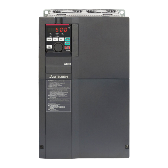
A800
FR-A802-P (SEPARATED CONVERTER TYPE FOR PARALLEL OPERATION)
INSTRUCTION MANUAL (HARDWARE)
High functionality and high performance
FR-A842-09620(400K) to 12120(500K)-P
INTRODUCTION
INSTALLATION AND WIRING
PRECAUTIONS FOR USE OF
THE INVERTER
PROTECTIVE FUNCTIONS
PRECAUTIONS FOR
MAINTENANCE AND
INSPECTION
SPECIFICATIONS
1
2
3
4
5
6
Advertisement
Table of Contents

Related Manuals for Mitsubishi Electric A800


Summary of Contents for Mitsubishi Electric A800
- Page 1 INVERTER A800 FR-A802-P (SEPARATED CONVERTER TYPE FOR PARALLEL OPERATION) INSTRUCTION MANUAL (HARDWARE) High functionality and high performance FR-A842-09620(400K) to 12120(500K)-P INTRODUCTION INSTALLATION AND WIRING PRECAUTIONS FOR USE OF THE INVERTER PROTECTIVE FUNCTIONS PRECAUTIONS FOR MAINTENANCE AND INSPECTION SPECIFICATIONS...
- Page 2 (separated converter type for parallel operation) that are different from the FR-A800. Information about the software, such as basic operations and parameters, is described in the FR-A800 Instruction Manual (Detailed) in the CD-ROM enclosed with the product. Also, for information about the parameters and restrictions on the parallel operation specifications, refer to the Parallel Operation Function Manual in the enclosed CD-ROM.
- Page 3 CAUTION CAUTION Transportation and Mounting Usage The storage temperature (applicable for a short time, e.g. during The electronic thermal relay function does not guarantee transit) must be between -20 and +65°C. Otherwise the inverter protection of the motor from overheating. It is recommended to may be damaged.
-
Page 4: Table Of Contents
CONTENTS 1 INTRODUCTION Product checking and accessories Inverter component names About the related manuals 2 INSTALLATION AND WIRING Peripheral devices 2.1.1 Inverter and peripheral devices ........................12 2.1.2 Peripheral devices ............................13 Removal and reinstallation of the operation panel or the front covers Installation of the inverter and enclosure design 2.3.1 Inverter installation environment........................17... - Page 5 Electro-magnetic interference (EMI) and leakage currents 3.1.1 Leakage currents and countermeasures......................62 3.1.2 Countermeasures against inverter-generated EMI ..................65 3.1.3 Converter unit built-in EMC filter ........................68 Power supply harmonics 3.2.1 Power supply harmonics ..........................69 3.2.2 Harmonic Suppression Guidelines in Japan ....................70 Power-OFF and magnetic contactor (MC) Countermeasures against deterioration of the 400 V class motor insulation Checklist before starting operation...
- Page 6 6 SPECIFICATIONS Inverter rating Common specifications Outline dimension drawings APPENDIX Appendix 1 Instructions for compliance with the EU Directives............106 Appendix 2 Instructions for UL and cUL ....................109 Appendix 3 Instructions for EAC......................111 Appendix 4 Restricted Use of Hazardous Substances in Electronic and Electrical Products ... 112 CONTENTS...
- Page 7 MEMO...
-
Page 8: Introduction
INTRODUCTION This chapter contains the descriptions that must be read before using this product. Always read the instructions before using the equipment. 1.1 Product checking and accessories.........8 1.2 Inverter component names ............9 <Abbreviations> DU........... Operation panel (FR-DU08) Operation panel ......Operation panel (FR-DU08) and LCD operation panel (FR-LU08) Parameter unit ........ -
Page 9: Product Checking And Accessories
Product checking and accessories Product checking and accessories Unpack the product and check the rating plate and the capacity plate of the inverter to ensure that the model agrees with the order and the product is intact. Applicable inverter model ∗1 Symbol Description... -
Page 10: Inverter Component Names
Cooling fan Cools the inverter. Switches for manufacturer setting ─ Do not change the initial setting (OFF (SW3 and SW4) Refer to the FR-A800 Instruction Manual (Detailed). The Vector control compatible options cannot be used with the slave. INTRODUCTION... -
Page 11: About The Related Manuals
About the related manuals About the related manuals The manuals related to this inverter are shown below. Manual name Manual number Parallel Operation Function Manual IB-0600654ENG FR-A800 Instruction Manual (Detailed) IB-0600503ENG FR-CC2-P Instruction Manual IB-0600657ENG INTRODUCTION... -
Page 12: Installation And Wiring
INSTALLATION AND WIRING This chapter explains the "installation" and the "wiring" of this product. Always read the instructions before using the equipment. 2.1 Peripheral devices ..............12 2.2 Removal and reinstallation of the operation panel or the front covers ................15 2.3 Installation of the inverter and enclosure design ....17 2.4 Terminal connection diagrams ..........24... -
Page 13: Peripheral Devices
Peripheral devices Peripheral devices 2.1.1 Inverter and peripheral devices • For operating two inverters in parallel One circuit breaker and one magnetic contactor in total in a system (c) Three-phase AC (d) Molded case circuit (e) Magnetic power supply breaker (MCCB) or fuse contactor (MC) (f) Noise filter... -
Page 14: Peripheral Devices
Peripheral devices Refer Symbol Name Overview page The life of the inverter and the converter unit is influenced by the surrounding air temperature. Inverter (FR-A802-P) The surrounding air temperature should be as low as possible within the permissible range. This must be noted especially when the inverter is installed in an enclosure. - Page 15 Peripheral devices Selecting the breaker/magnetic contactor Check the model of the inverter and the converter unit you purchased. Appropriate peripheral devices must be selected according to the capacity. Refer to the table below to prepare appropriate peripheral devices. • One circuit breaker and one magnetic contactor in total in a system Motor Molded case circuit breaker (MCCB) ...
-
Page 16: Removal And Reinstallation Of The Operation Panel Or The Front Covers
Removal and reinstallation of the operation panel or the front covers Removal and reinstallation of the operation panel or the front covers Removal and reinstallation of the operation panel • Loosen the two screws on the operation panel. • Push the upper part of the operation panel and pull the (These screws cannot be removed.) operation panel to remove. - Page 17 Removal and reinstallation of the operation panel or the front covers Removal of the front cover (upper side) Loosen Loosen Loosen With the front cover (lower side) removed, loosen the mounting screws on the front cover (upper side). These screws cannot be removed.
-
Page 18: Installation Of The Inverter And Enclosure Design
Installation of the inverter and enclosure design Installation of the inverter and enclosure design When designing or manufacturing an inverter enclosure, determine the structure, size, and device layout of the enclosure by fully considering the conditions such as heat generation of the contained devices and the operating environment. An inverter uses many semiconductor devices. - Page 19 Installation of the inverter and enclosure design Humidity Operate the inverter within the ambient air humidity of usually 45 to 90% (up to 95% with circuit board coating). Too high humidity will pose problems of reduced insulation and metal corrosion. On the other hand, too low humidity may cause a spatial electrical breakdown.
-
Page 20: Amount Of Heat Generated By The Inverter
Installation of the inverter and enclosure design Vibration, impact The vibration resistance of the inverter is up to 2.9 m/s at 10 to 55 Hz frequency and 1 mm amplitude for the directions of X, Y, Z axes. Applying vibration and impacts for a long time may loosen the structures and cause poor contacts of connectors, even if those vibration and impacts are within the specified values. -
Page 21: Cooling System Types For Inverter Enclosure
Installation of the inverter and enclosure design 2.3.3 Cooling system types for inverter enclosure From the enclosure that contains the inverter, the heat of the inverter and other equipment (transformers, lamps, resistors, etc.) and the incoming heat such as direct sunlight must be dissipated to keep the in-enclosure temperature lower than the permissible temperatures of the in-enclosure equipment including the inverter. -
Page 22: Inverter Installation
Installation of the inverter and enclosure design 2.3.4 Inverter installation Inverter placement • Install the inverter on a strong surface securely with screws. • Leave enough clearances and take cooling measures. • Avoid places where the inverter is subjected to direct sunlight, high temperature and high humidity. •... -
Page 23: Protruding The Heatsink
Installation of the inverter and enclosure design Encasing multiple inverters and converter units When multiple inverters and converter units are placed in the same enclosure, generally arrange them horizontally as shown in the figure on the right. Converter Converter Inverter Inverter unit unit... - Page 24 Installation of the inverter and enclosure design Removal of the rear installation frame Two installation frames are attached to each of the upper and lower parts of the inverter. Remove the rear side installation frame on the top Upper installation and bottom of the inverter as shown on the right.
-
Page 25: Terminal Connection Diagrams
Terminal connection diagrams Terminal connection diagrams FM type Sink logic Main circuit terminal Control circuit terminal Converter unit R/L1 S/L2 To motor T/L3 Jumper R1/L11 S1/L21 Earth Main circuit (Ground) Control circuit Control input signals Relay output (No voltage input allowed) Forward rotation start Relay output 1 Reverse rotation start... - Page 26 Terminal connection diagrams Terminals R1/L11 and S1/L21 are connected to terminals P/+ and N/- with a jumper respectively. When using separate power supply for the control circuit, remove the jumpers from R1/L11 and S1/L21. The function of these terminals can be changed with the input terminal assignment (Pr.178 to Pr.189). ...
- Page 27 Terminal connection diagrams CA type Source logic Main circuit terminal Control circuit terminal Converter unit R/L1 S/L2 To motor T/L3 Jumper R1/L11 S1/L21 Earth Main circuit (Ground) Control circuit Control input signals Relay output (No voltage input allowed) Forward rotation start Relay output 1 Reverse rotation start...
- Page 28 Terminal connection diagrams Terminals R1/L11 and S1/L21 are connected to terminals P/+ and N/- with a jumper respectively. When using separate power supply for the control circuit, remove the jumpers from R1/L11 and S1/L21. The function of these terminals can be changed with the input terminal assignment (Pr.178 to Pr.189). ...
- Page 29 Terminal connection diagrams System configuration (for operating two inverters in parallel) • Install wiring of the RS-485 terminals in between the converter units and between the inverters as shown in the figure in page 29. (For the details of wiring of the RS-485 terminals, refer to page 50.) •...
- Page 30 Terminal connection diagrams • Terminal connection diagram for two inverters in parallel FR-CC2-P (master) FR-A802-P (master) Three-phase R/L1 AC power S/L2 supply T/L3 R1/L11 R1/L11 S1/L21 S1/L21 MRS(X10) TXD1+ TXD1+ TXD1- TXD1- TXD2+ TXD2+ TXD2- TXD2- RXD1+ RXD1+ RXD1- RXD1- RXD2+ RXD2+ RXD2-...
- Page 31 Terminal connection diagrams System configuration (for operating three inverters in parallel) • Install wiring of the RS-485 terminals in between the converter units and between the inverters as shown in the figure in page 31. (For the details of wiring of the RS-485 terminals, refer to page 50.) •...
- Page 32 Terminal connection diagrams • Terminal connection diagram for three inverters in parallel FR-CC2-P (master) FR-A802-P (master) Three-phase R/L1 AC power S/L2 supply T/L3 R1/L11 R1/L11 S1/L21 S1/L21 MRS(X10) TXD1+ TXD1+ TXD1- TXD1- TXD2+ TXD2+ TXD2- TXD2- RXD1+ RXD1+ RXD1- RXD1- RXD2+ RXD2+ RXD2-...
- Page 33 Terminal connection diagrams Wiring between the converter units and the inverters Main circuit terminal • Wire terminal P (+) on the converter unit to terminal P on the inverter, and do likewise for terminal N (-). Pair the masters or the slaves (1 with 1 or 2.with 2).
-
Page 34: Main Circuit Terminals
Main circuit terminals Main circuit terminals 2.5.1 Details on the main circuit terminals of the inverter Terminal Refer Terminal name Terminal function description symbol to page U, V, W Inverter output Connect these terminals to a three-phase squirrel cage motor. Connected to terminals P/+ and N/-. - Page 35 Main circuit terminals 2.5.3 Terminal layout of the main circuit terminals, wiring of power supply and the motor FR-CC2-H400K to H560K-P FR-A842-09620(400K) to 12120(500K)-P R1/L11 S1/L21 R1/L11 S1/L21 Charge lamp Charge lamp Jumper Jumper R/L1 T/L3 S/L2 To converter To motor To inverter Power supply unit...
-
Page 36: Applicable Cables And Wiring Length
Main circuit terminals 2.5.4 Applicable cables and wiring length Select a recommended cable size to ensure that the voltage drop will be 2% or less. If the wiring distance is long between the inverter and motor, the voltage drop in the main circuit will cause the motor torque to decrease especially at a low speed. - Page 37 Main circuit terminals Total wiring length The total wiring length between the inverters in parallel connection and a motor must be 500 m or less. It is determined by calculating the sum of length of "a" (a cable from the master inverter to the node point), "a' " (a cable from each slave inverter to the node point), and "b"...
-
Page 38: Earthing (Grounding) Precautions
Main circuit terminals 2.5.5 Earthing (grounding) precautions • Always earth (ground) the motor, the inverter, and the converter unit. Purpose of earthing (grounding) Generally, an electrical apparatus has an earth (ground) terminal, which must be connected to the ground before use. An electrical circuit is usually insulated by an insulating material and encased. -
Page 39: Control Circuit
Details on the control circuit terminals of the inverter The input signal function of the terminals in can be selected by setting Pr.178 to Pr.196 (I/O terminal function selection). For the parameter details, refer to the FR-A800 Instruction Manual (Detailed). Input signal Terminal Rated Terminal name... - Page 40 Applying a voltage with the voltage/current input switch ON (current input is selected) or a current with the switch OFF (voltage input is selected) could cause component damage of the inverter or analog circuits of output devices. (For the details, refer to the FR-A800 Instruction Manual (Detailed).)
- Page 41 Control circuit Terminal Rated Terminal name Terminal function description symbol Specification Switched to LOW when the inverter output frequency is equal to or Inverter running higher than the starting frequency (initial value 0.5 Hz). Switched to Permissible load 24 HIGH during stop or DC injection brake operation. VDC (maximum 27 Switched to LOW when the output frequency VDC) 0.1 A...
-
Page 42: Details On The Control Circuit Terminals Of The Converter Unit
Control circuit Terminals for manufacturer setting Terminal Terminal function description symbol Terminals S1, S2, SIC, So (SO), and SOC are for manufacturer setting. Do not connect anything to these. Doing so may cause an inverter failure. Do not remove the shorting wires across terminals S1 and PC, terminals S2 and PC, and terminals SIC and SD. So (SO) Removing either shorting wire disables the inverter operation. -
Page 43: Control Logic (Sink/Source) Change
Control circuit Output signal Terminal Terminal name Terminal function description Rate Specification symbol 1 changeover contact output that indicates that the protective function of Contact capacity Relay output 1 (fault the converter unit has been activated and the outputs are stopped. 230 VAC 0.3 A output) Fault: discontinuity across B and C (continuity across A and C), Normal:... - Page 44 Control circuit Sink logic and source logic • In the sink logic, a signal switches ON when a current flows from the corresponding signal input terminal. Terminal SD is common to the contact input signals. Terminal SE is common to the open collector output signals. •...
-
Page 45: Wiring Of Inverter Control Circuit
Control circuit 2.6.4 Wiring of inverter control circuit Control circuit terminal layout ∗1 1 F/C +24 SD So SOC S1 S2 PC 5 10E 10 SE SE IPF OL FU PC RL RM RH RT AU STP MRS SD SD STF STR JOG ∗4 ∗2... - Page 46 Control circuit NICHIFU Co., Ltd. Cable gauge Blade terminal Insulation cap Crimping tool product number product number product number 0.3 to 0.75 BT 0.75-11 VC 0.75 NH 69 (3) Insert the wires into a socket. When using a single wire or stranded wires without a blade terminal, push the open/close button all the way down with a flathead screwdriver, and insert the wire.
-
Page 47: Wiring Precautions
Control circuit Signal inputs by contactless switches The contact input terminals of the inverter (STF, STR, STOP, RH, RM, RL, JOG, RT, MRS, RES, AU, CS) can be controlled using a transistor instead of a contact switch as shown below. Inverter +24 V +24 V... -
Page 48: When Using Separate Power Supplies For The Control Circuit And The Main Circuit
Control circuit 2.6.6 When using separate power supplies for the control circuit and the main circuit Cable size for the control circuit power supply (terminals R1/L11 and S1/ L21) • Terminal screw size: M4 • Cable gauge: 0.75 mm to 2 mm •... -
Page 49: When Supplying 24 V External Power To The Control Circuit
Control circuit 2.6.7 When supplying 24 V external power to the control circuit Connect the 24 V external power supply across terminals +24 and SD. The 24 V external power supply enables I/O terminal ON/OFF operation, operation panel displays, control functions, and communication during communication operation even during power-OFF of inverter's main circuit power supply. - Page 50 Control circuit Operation while the 24 V external power is supplied • Faults history and parameters can be read and parameters can be written (when the parameter write from the operation panel is enabled) using the operation panel keys. • During the 24 V external power supply operation, monitored items and signals related to inputs to main circuit power supply, such as output current and converter output voltage, are invalid.
-
Page 51: Communication Connectors And Terminals
Communication connectors and terminals Communication connectors and terminals 2.7.1 RS-485 terminal block Connecting between the RS-485 terminals of the master/slave inverters enables communication for the parallel operation. For wiring, refer to page RS-485 terminal layout Terminating resistor switch Name Description Initially-set to "OPEN". - Page 52 Communication connectors and terminals RS-485 terminal wiring method • For operating two inverters in parallel Ferrite core ∗1 Master station Slave station • For operating three inverters in parallel Ferrite core Ferrite core ∗1 Master station Slave station 1 Slave station 2 ...
-
Page 53: Pu Connector
FA or other computer by a communication cable, a user program can run to monitor the inverter or read and write parameters. Communication can be performed with the Mitsubishi inverter protocol (computer link operation). (For details, refer to the FR-A800 Instruction Manual (Detailed).) INSTALLATION AND WIRING... -
Page 54: Usb Connector
• Do not connect devices other than a USB memory device to the inverter. • If a USB device is connected to the inverter via a USB hub, the inverter cannot recognize the USB memory device properly. • For the details of usage, refer to the FR-A800 Instruction Manual (Detailed). INSTALLATION AND WIRING... -
Page 55: Connection Of Motor With Encoder (Vector Control)
Connection of motor with encoder (Vector control) Connection of motor with encoder (Vector control) Using encoder-equipped motors together with a vector control compatible option enables speed, torque, and positioning control operations under orientation control, encoder feedback control, and full-scale vector control. (The Vector control compatible options can be installed only to the master inverter.) This section explains wiring for use of the FR-A8AP. - Page 56 Connection of motor with encoder (Vector control) Switches of the FR-A8AP • Encoder type selection switch (SW3) Differential line Selects either the differential line driver or complementary setting. driver (initial status) It is initially set to the differential line driver. Switch its position according to the output circuit.
- Page 57 • Shield earthing P-clip is Model Length L (m) Model Length L (m) included. FR-JCBL5 FR-V7CBL5 FR-JCBL15 FR-V7CBL15 FR-JCBL30 FR-V7CBL30 FR-A800 FR-A800 (FR-A8AP) (FR-A8AP) Positioning keyway Positioning keyway D/MS3106B20-29S D/MS3106B20-29S (As viewed from wiring side) (As viewed from wiring side) 2 mm 2 mm ...
- Page 58 Connection of motor with encoder (Vector control) • Connection terminal compatibility table Encoder cable FR-V7CBL FR-JCBL Do not connect anything to this. Do not connect anything to this. FR-A8AP terminal Do not connect anything to this. Wiring example • Speed control Vector control dedicated motor, Standard motor with encoder, 5 V differential line driver 12 V complementary...
- Page 59 Connection of motor with encoder (Vector control) • Position control Vector control dedicated motor, 12 V complementary Positioning unit Vector control MELSEC-Q QD75P[]N/QD75P[] dedicated motor MELSEC-L LD75P[] Inverter To converter unit Earth (ground) STOP Forward stroke end FR-A8AP Reverse stroke end ∗1 Pre-excitation/servo on ∗7...
- Page 60 To protect the cables from noise, run them away from any source of noise (such as the main circuit and power supply voltage). Example of parallel connection with two cables (with complementary encoder output) FR-A800 (FR-A8AP) Encoder 2 mm Wiring length...
-
Page 61: Parameter Settings For A Motor With Encoder
Number of Constant-torque motor Rated motor current 1 (13) Motor capacity motor poles Offline auto tuning is required (Refer to the FR-A800 Instruction Manual (Detailed)) Set this parameter according to the motor. INSTALLATION AND WIRING... -
Page 62: Precautions For Use Of The Inverter
PRECAUTIONS FOR USE OF THE INVERTER This chapter explains the precautions for use of this product. Always read the instructions before using the equipment. 3.1 Electro-magnetic interference (EMI) and leakage currents ..62 3.2 Power supply harmonics ............69 3.3 Power-OFF and magnetic contactor (MC) ......72 3.4 Countermeasures against deterioration of the 400 V class motor... -
Page 63: Electro-Magnetic Interference (Emi) And Leakage Currents Leakage Currents And Countermeasures
Electro-magnetic interference (EMI) and leakage currents Electro-magnetic interference (EMI) and leakage currents 3.1.1 Leakage currents and countermeasures Capacitances exist between the inverter I/O cables, other cables and earth and in the motor, through which a leakage current flows. Its value depends on the static capacitances, etc. Take the following countermeasures. To select the earth leakage circuit breaker, refer to its rated sensitivity current. - Page 64 Electro-magnetic interference (EMI) and leakage currents Selecting the rated sensitivity current for the earth leakage circuit breaker When using the earth leakage circuit breaker with the inverter circuit, select its rated sensitivity current as follows. • Breaker designed for harmonic and surge suppression Ig1, Ig2: Leakage currents in wire path during commercial Rated sensitivity current...
- Page 65 Electro-magnetic interference (EMI) and leakage currents NOTE • Install the earth leakage circuit breaker (ELB) on the input side of the converter unit. • In the connection earthed-neutral system, the sensitivity current is blunt against a ground fault in the inverter output side. Earthing (Grounding) must conform to the requirements of national and local safety regulations and electrical codes.
-
Page 66: Countermeasures Against Inverter-Generated Emi
Electro-magnetic interference (EMI) and leakage currents 3.1.2 Countermeasures against inverter-generated Some electromagnetic noises enter the inverter or the converter unit to cause its malfunction, and others are radiated by the inverter or the converter unit to cause the peripheral devices to malfunction. Though the inverter or the converter unit is designed to have high immunity performance, it handles low-level signals, so it requires the following basic techniques. - Page 67 Electro-magnetic interference (EMI) and leakage currents Noise Countermeasure propagation path When devices that handle low-level signals and are liable to malfunction due to electromagnetic noises, e.g. instruments, receivers and sensors, are contained in the enclosure that contains the inverter or the converter unit, or when their signal cables are run near the inverter, the devices may malfunction due to by air-propagated electromagnetic noises.
- Page 68 Electro-magnetic interference (EMI) and leakage currents EMI countermeasure example Enclosure Install filter on inverter output side. Inverter Line noise Converter power Inverter Motor filter filter unit supply Use 4-core cable for motor Separate inverter, power cable and use one cable converter unit and as earth (ground) cable.
-
Page 69: Converter Unit Built-In Emc Filter
Electro-magnetic interference (EMI) and leakage currents 3.1.3 Converter unit built-in EMC filter The converter unit (FR-CC2) is equipped with a built-in EMC filter (capacitive filter). These filters are effective in reducing air-propagated noise on the input side of the converter unit. Two EMC filter ON/OFF connectors are provided. -
Page 70: Power Supply Harmonics Power Supply Harmonics
Power supply harmonics Power supply harmonics 3.2.1 Power supply harmonics The inverter may generate power supply harmonics from its converter circuit to affect the power generator, power factor correction capacitor etc. Power supply harmonics are different from noise and leakage currents in source, frequency band and transmission path. -
Page 71: Harmonic Suppression Guidelines In Japan
Power supply harmonics 3.2.2 Harmonic Suppression Guidelines in Japan Inverters have a converter section (rectifier circuit) and generate a harmonic current. The Harmonic Suppression Guidelines was established to protect other consumers from these outgoing harmonic currents. The three-phase 200 V input specifications 3.7 kW or lower were previously covered by "the Harmonic Suppression Guidelines for Household Appliances and General-purpose Products"... - Page 72 Power supply harmonics • Calculation of equivalent capacity P0 of harmonic generating equipment "Equivalent capacity" is the capacity of a 6-pulse converter converted from the capacity of consumer's harmonic generating equipment and is calculated by the following equation: If the sum of equivalent capacities is higher than the limit in (refer to page 70), harmonics must be calculated with the following procedure: P0 = ∑...
-
Page 73: Power-Off And Magnetic Contactor (Mc)
Power-OFF and magnetic contactor (MC) Power-OFF and magnetic contactor (MC) Converter unit input side magnetic contactor (MC) On the converter unit input side, it is recommended to provide an MC for the following purposes: (Refer to page 13 for selection.) •... -
Page 74: Countermeasures Against Deterioration Of The 400 V Class Motor Insulation
Countermeasures against deterioration of the 400 V class motor insulation Countermeasures against deterioration of the 400 V class motor insulation In the PWM type inverter, a surge voltage attributable to wiring constants is generated at the motor terminals. Especially in a 400 V class motor, the surge voltage may deteriorate the insulation. -
Page 75: Checklist Before Starting Operation
Checklist before starting operation Checklist before starting operation The FR-A800 series inverter and converter unit are highly reliable products, but incorrect peripheral circuit making or operation/handling method may shorten the product life or damage the products. Before starting operation, always recheck the following points. - Page 76 Checklist before starting operation Refer Check Checkpoint Countermeasure to page by user Application of a voltage higher than the permissible voltage to the I/O signal The voltage applied to the I/O signal circuits of the inverter and the converter unit or opposite polarity may circuits of the inverter and the damage the I/O devices.
- Page 77 Checklist before starting operation Refer Check Checkpoint Countermeasure to page by user When performing frequent starts/stops by the inverter, rise/fall in the temperature of the transistor element of the inverter will repeat due to a repeated flow of large current, shortening the life from thermal fatigue.Since thermal fatigue is related to the amount of current, the life can be increased A countermeasure is provided for an by reducing current at locked condition, starting current, etc.
-
Page 78: Failsafe System Which Uses The Inverter
Failsafe system which uses the inverter Failsafe system which uses the inverter When a fault is detected by the protective function, the protective function is activated and outputs a fault signal. However, a fault signal may not be output at an inverter's fault occurrence when the detection circuit or output circuit fails, etc. Although Mitsubishi assures the best quality products, provide an interlock which uses inverter status output signals to prevent accidents such as damage to the machine when the inverter fails for some reason. - Page 79 • Changing the terminal assignment using Pr.190 and Pr.196 (Output terminal function selection) may affect the other functions. Set parameters after confirming the function of each terminal. • For the details of the parameters and signals, refer to the FR-A800 Instruction Manual (Detailed). Backup method outside the inverter Even if the interlock is provided by the inverter status signal, enough failsafe is not ensured depending on the failure status of the inverter itself.
-
Page 80: Protective Functions
PROTECTIVE FUNCTIONS This chapter explains the "PROTECTIVE FUNCTIONS" that operates in this product. Always read the instructions before using the equipment. 4.1 Inverter fault and alarm indications ........80 4.2 Reset method for the protective functions......80 4.3 Check and clear of the faults history ........81 4.4 List of fault displays ..............83... -
Page 81: Inverter Fault And Alarm Indications
A protective function is activated to shut off the inverter output and output a Fault (ALM) signal. NOTE • For the details of fault displays and other malfunctions, refer to the FR-A800 Instruction Manual (Detailed). • The past eight faults can be displayed on the operation panel. (Faults history) (For the operation, refer to page 81.) -
Page 82: Check And Clear Of The Faults History
Check and clear of the faults history Check and clear of the faults history The operation panel stores the fault indications which appears when a protective function is activated to display the fault record for the past eight faults. (Faults history) Check for the faults history Monitor mode Parameter setting mode... - Page 83 Check and clear of the faults history Faults history clearing procedure POINT POINT • Set Err.CL Fault history clear = "1" to clear the faults history. Operation Screen at power-ON The monitor display appears. Parameter setting mode Press to choose the parameter setting mode. (The parameter number read previously appears.) Selecting the parameter number Turn until "...
-
Page 84: List Of Fault Displays
Availability of the protective function for the master and the slave during the parallel operation are as follows. indicates that the protective function is enabled. indicates that the protective function is disabled. For the details of each protective function, refer to the Instruction Manual (Detailed) of the FR-A800 or the Parallel Operation Function Manual. - Page 85 List of fault displays Master Slave Operation panel indication Name station station E.OLT Stall prevention stop E.GF Output side earth (ground) fault overcurrent E.LF Output phase loss E.OHT External thermal relay operation E.PTC PTC thermistor operation ...
- Page 86 List of fault displays Master Slave Operation panel indication Name station station E---- Faults history 24 V external power supply operation Backup in progress Restoration in progress SLV.1 Parallel operation slave 1 ...
- Page 87 MEMO...
-
Page 88: Precautions For Maintenance And Inspection
PRECAUTIONS FOR MAINTENANCE AND INSPECTION This chapter explains the "PRECAUTIONS FOR MAINTENANCE AND INSPECTION" for this product. Always read the instructions before using the equipment. 5.1 Inspection item................88 5.2 Measurement of main circuit voltages, currents and powers ..................94 PRECAUTIONS FOR MAINTENANCE AND INSPECTION... -
Page 89: Inspection Item Daily Inspection
Inspection item The inverter is a static unit mainly consisting of semiconductor devices. Daily inspection must be performed to prevent any fault from occurring due to the adverse effects of the operating environment, such as temperature, humidity, dust, dirt and vibration, changes in the parts with time, service life, and other factors. -
Page 90: Daily And Periodic Inspection
Contact the manufacturer. deformation trace. Aluminum electrolytic (2) Visual check and judge by the life check of the capacitor control circuit capacitor. (Refer to the FR-A800 Instruction Manual (Detailed)). (1) Check for unusual vibration and noise. Replace the fan. ... -
Page 91: Checking The Inverter And Converter Modules
Inspection item 5.1.4 Checking the inverter and converter modules Preparation • Disconnect the external power supply cables (R/L1, S/L2, T/L3) and motor cables (U, V, W). (The cables between the inverter and the converter unit, between the inverters, and between the converter units does not need to be removed.) •... -
Page 92: Cleaning
Parts Judgment level Control circuit capacitor Estimated remaining life 10% Cooling fan Approx. less than 1700 r/min NOTE • Refer to the FR-A800 Instruction Manual (Detailed) to perform the life check of the inverter parts. PRECAUTIONS FOR MAINTENANCE AND INSPECTION... - Page 93 Inspection item Replacement procedure of the cooling fan The replacement interval of the cooling fan used for cooling the parts generating heat such as the main circuit semiconductor is greatly affected by the surrounding air temperature. When unusual noise and/or vibration are noticed during inspection, the cooling fan must be replaced immediately.
-
Page 94: Inverter Replacement
• Check for external crack, discoloration, liquid leakage, etc. Judge that the capacitor has reached its life when the measured capacitance of the capacitor reduced below 80% of the rating. NOTE • The inverter diagnoses the control circuit capacitor by itself and can judge its life. (Refer to the FR-A800 Instruction Manual (Detailed)) Relays •... -
Page 95: Measurement Of Main Circuit Voltages, Currents And Powers
Measurement of main circuit voltages, currents and powers Measurement of main circuit voltages, currents and powers Since the voltages and currents on the inverter power supply and output sides include harmonics, measurement data depends on the instruments used and circuits measured. When instruments for commercial frequency are used for measurement, measure the following circuits with the instruments given on the next page. - Page 96 Measurement of main circuit voltages, currents and powers Measuring points and instruments Item Measuring point Measuring instrument Remarks (reference measured value) Power supply Across R/L1 and S/L2, Commercial power supply voltage S/L2 and T/L3, Moving-iron type AC voltmeter Within permissible AC voltage fluctuation (Refer ...
-
Page 97: Measurement Of Powers
Measurement of main circuit voltages, currents and powers Use an FFT to measure the output voltage accurately. A tester or general measuring instrument cannot measure accurately. When the setting of Pr.195 ABC1 terminal function selection is the positive logic ... -
Page 98: Measurement Of Currents
Measurement of main circuit voltages, currents and powers 5.2.3 Measurement of currents Use moving-iron type meter on the input side of the converter unit and the output side of the inverter. Since current on the converter unit input side tends to be unbalanced, measurement of three phases is recommended. Correct value cannot be obtained by measuring only one or two phases. -
Page 99: Measurement Of Inverter Output Frequency
5 VDC is indicated at the maximum frequency. For detailed specifications of the pulse train output terminal FM, refer to the FR-A800 Instruction Manual (Detailed). In the initial setting of the CA-type inverter, a pulse train proportional to the output frequency is output across the analog current output terminals CA and 5 of the inverter. -
Page 100: Specifications
SPECIFICATIONS This chapter explains the "SPECIFICATIONS" of this product. Always read the instructions before using the equipment. 6.1 Inverter rating................100 6.2 Common specifications ............101 6.3 Outline dimension drawings............103 SPECIFICATIONS... -
Page 101: Inverter Rating
However, the maximum point of the voltage waveform at the inverter output side is the power supply voltage multiplied by about ND rating reference value For the power voltage exceeding 480 V, set Pr.977 Input voltage mode selection. (For details, refer to the FR-A800 Instruction Manual (Detailed).) FR-DU08: IP40 (except for the PU connector section) ... -
Page 102: Common Specifications
Common specifications Common specifications Soft-PWM control, PWM control (selectable among V/F control, Advanced magnetic flux vector control, Real sensorless Control method vector control), and vector control Output frequency range 0.2 to 120 Hz 0.015 Hz/60 Hz (terminal 2, 4: 0 to 10 V/12 bits) Frequency Analog input 0.03 Hz/60 Hz (0 to 5 V/11 bits or 0 to 20 mA/approx. - Page 103 Common specifications Surrounding air -10°C to +50°C (non-freezing) temperature 95% RH or less (non-condensing) (With circuit board coating (conforming to IEC60721-3-3 3C2/3S2)) Surrounding air humidity 90% RH or less (non-condensing) (Without circuit board coating) Storage temperature -20°C to +65°C Atmosphere Indoors (without corrosive gas, flammable gas, oil mist, dust and dirt, etc.) Altitude/vibration...
-
Page 104: Outline Dimension Drawings
Outline dimension drawings Outline dimension drawings FR-A842-09620(400K), 10940(450K), 12120(500K)-P 3-φ12 hole 8-φ25 hole (100) (Unit: mm) Operation panel (FR-DU08) Outline drawing Panel cutting dimension drawing 120 or more ∗1 Panel 3.2max 27.8 Operation panel FR-DU08 connection cable (FR-CB2[ ] )(option) Air-bleeding hole Operation panel... - Page 105 MEMO...
-
Page 106: Appendix
APPENDIX APPENDIX provides the reference information for use of this product. Refer to APPENDIX as required. Appendix 1 Instructions for compliance with the EU Directives ..106 Appendix 2 Instructions for UL and cUL .........109 Appendix 3 Instructions for EAC .............111 Appendix 4 Restricted Use of Hazardous Substances in Electronic and Electrical Products ......112... -
Page 107: Appendix 1 Instructions For Compliance With The Eu Directives
CE marking. • The authorized representative in the EU The authorized representative in the EU is shown below. Company name: Mitsubishi Electric Europe B.V. Address: Mitsubishi-Electric-Platz 1, 40882 Ratingen, Germany • Note We declare that this inverter conforms with the EMC Directive in industrial environments and affix the CE marking on the inverter. - Page 108 Low Voltage Directive We have self-confirmed our inverters as products compliant to the Low Voltage Directive (Conforming standard EN 61800-5- 1) and affix the CE marking on the inverters. Outline of instructions • Do not use an earth leakage current breaker as an electric shock protector without connecting the equipment to the earth.
- Page 109 However, the maximum point of the voltage waveform at the inverter output side is the power supply voltage multiplied by about FR-DU08: IP40 (except for the PU connector section) For the power voltage exceeding 480 V, set Pr.977 Input voltage mode selection. (For details, refer to the FR-A800 Instruction Manual (Detailed).) APPENDIX...
-
Page 110: Appendix 2 Instructions For Ul And Cul
Appendix 2 Instructions for UL and cUL (Standard to comply with: UL 508C, CSA C22.2 No.14) General Precaution CAUTION - Risk of Electric Shock - The bus capacitor discharge time is 10 minutes. Before starting wiring or inspection, switch power off, wait for more than 10 minutes, and check for residual voltage between terminal P/+ and N/- with a meter etc., to avoid a hazard of electrical shock. - Page 111 However, the maximum point of the voltage waveform at the inverter output side is the power supply voltage multiplied by about FR-DU08: IP40 (except for the PU connector section) For the power voltage exceeding 480 V, set Pr.977 Input voltage mode selection. (For details, refer to the FR-A800 Instruction Manual (Detailed).) APPENDIX...
-
Page 112: Appendix 3 Instructions For Eac
• Authorized sales representative (importer) in the CU area The authorized sales representative (importer) in the CU area is shown below. Name: Mitsubishi Electric (Russia) LLC Address: 52, bld 1 Kosmodamianskaya Nab 115054, Moscow, Russia Phone: +7 (495) 721-2070... -
Page 113: Appendix 4 Restricted Use Of Hazardous Substances In Electronic And Electrical Products
Appendix 4 Restricted Use of Hazardous Substances in Electronic and Electrical Products The mark of restricted use of hazardous substances in electronic and electrical products is applied to the product as follows based on the “Management Methods for the Restriction of the Use of Hazardous Substances in Electrical and Electronic Products”... - Page 114 WARRANTY When using this product, make sure to understand the warranty described below. 1. Warranty period and coverage We will repair any failure or defect (hereinafter referred to as "failure") in our FA equipment (hereinafter referred to as the "Product") arisen during warranty period at no charge due to causes for which we are responsible through the distributor from which you purchased the Product or our service provider.
- Page 115 • The copyright and other rights of the enclosed CD-ROM all belong to Mitsubishi Electric Corporation. • No part of the enclosed CD-ROM may be copied or reproduced without the permission of Mitsubishi Electric Corporation. • Specifications of the enclosed CD-ROM are subject to change for modification without notice.
- Page 116 MEMO...
- Page 117 REVISIONS *The manual number is given on the bottom left of the back cover. Print Date *Manual Number Revision Nov. 2016 IB(NA)-0600651ENG-A First edition For Maximum Safety • Mitsubishi inverters are not designed or manufactured to be used in equipment or systems in situations that can affect or endanger human life.
- Page 118 HEAD OFFICE: TOKYO BUILDING 2-7-3, MARUNOUCHI, CHIYODA-KU, TOKYO 100-8310, JAPAN IB(NA)-0600651ENG-A(1611)MEE Printed in Japan Specifications subject to change without notice.
Need help?
Do you have a question about the A800 and is the answer not in the manual?
Questions and answers