
Related Manuals for ADTRAN HDSL 3192 HTU-C


Summary of Contents for ADTRAN HDSL 3192 HTU-C
- Page 1 ® HDSL 3192 HTU-C Installation and Maintenance Practice Document Number: 61247004L1-5A CLEI: T1I3AAPA_ _ April 2008...
- Page 2 In no event will ADTRAN be liable for any special, incidental, or consequential damages or for commercial losses even if ADTRAN has been advised thereof as a result of issue of this document.
- Page 3 Revision History Revision Date Description April 2008 Initial release Conventions The following typographical conventions are used in this document: This font indicates a cross-reference link. indicates screen menus, fields, and parameters. This font indicates keyboard keys ( ). Keys that are to be pressed simultaneously HIS FONT NTER are shown with a plus sign (...
- Page 4 HDSL 3192 HTU-C Installation and Maintenance Practice Training ADTRAN offers training courses on our products. These courses include overviews on product features and functions while covering applications of ADTRAN product lines. ADTRAN provides a variety of training options, including customized training and courses taught at our facilities or at customer sites.
-
Page 5: Table Of Contents
Contents Introduction ................1 Description. - Page 6 ADTRAN Technical Support ........
- Page 7 ADTRAN Noise Margin Guidelines ........
- Page 8 HDSL 3192 HTU-C Installation and Maintenance Practice This page is intentionally blank. viii 61247004L1-5A...
-
Page 9: Introduction
HDSL 3192 HTU-C INTRODUCTION This practice is an installation and maintenance guide for the ADTRAN HDSL 3192 HTU-C ® (3192 HTU-C). The 3192 HTU-C (P/N 1247004L1) is used to deploy an HDSL T1 circuit using 4-wire metallic facilities. The unit occupies one slot in a 3192 shelf. -
Page 10: Description
DSX 1 signals are provided to and received from the network while 2B1Q HDSL signals are provided to the local loop. The 3192 HTU-C works in conjunction with the ADTRAN HDSL Transceiver Unit for Remote Office (HTU-R) and HDSL Range Extender (HRE) to provide a DS1 service up to 36,000 feet on the local loop. -
Page 11: Compliance
2. This device must accept any interference received, including interference that may cause undesired operation. Changes or modifications not expressly approved by ADTRAN could void the user’s authority to operate this equipment. The compliance codes for the 3192 HTU-C are listed in Table Table 2. - Page 12 HDSL 3192 HTU-C Installation and Maintenance Practice CAUTION Per GR-1089-CORE Section 9, the 3192 HTU-C does not have an internal DC connection between battery return and frame ground. As such, it may be installed in a DC-I (isolated) or DC-C (common) installation.
-
Page 13: Hdsl Deployment Guidelines
HDSL Deployment Guidelines HDSL DEPLOYMENT GUIDELINES The ADTRAN HDSL system is designed to provide DS1 based services over loops designed to comply with carrier service area (CSA) guidelines. CSA deployment guidelines are given below. • All loops are non-loaded only. -
Page 14: Table 3. Hdsl Loss Values
HDSL 3192 HTU-C Installation and Maintenance Practice Table 3. HDSL Loss Values (200 kHz cable loss in dB/kft at 135 Ω) Temperature: Cable Gauge Cable Type 68° 90° 120° 3.902 4.051 4.253 Pulp 4.030 4.179 4.381 2.863 2.957 3.083 Pulp 3.159... -
Page 15: Installation
After unpacking the 3192 HTU-C, inspect it for damage. If damage has occurred, file a claim with the carrier then contact ADTRAN Customer Service. Refer to “Appendix C, Warranty” further information. If possible, keep the original shipping container for returning the 3192 HTU-C for repair or for verification of shipping damage. -
Page 16: Line Build Out Switch
HDSL 3192 HTU-C Installation and Maintenance Practice Line Build Out Switch The line build out switch is located on the printed circuit board. Manual configuration should be performed prior to installing the 3192 HTU-C. The available settings are shown in Table Table 5. -
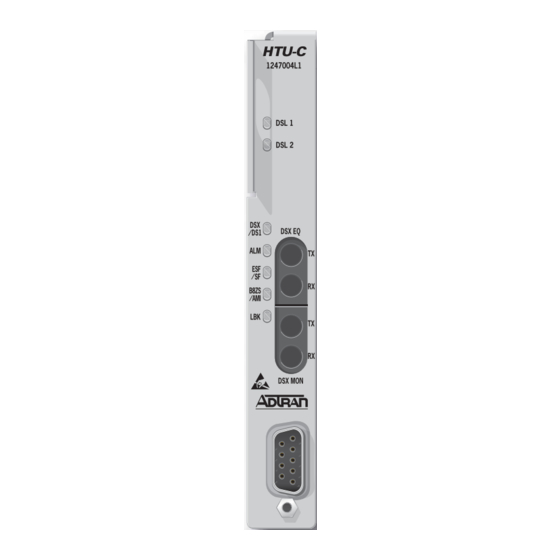
Page 17: Front Panel Leds
Installation Front Panel LEDs The 3192 HTU-C provides front panel LEDs to display status information. The 3192 HTU-C LEDs and status descriptions are shown in Table Table 6. Front Panel LEDs Label Status Description No sync between the HTU-C and HTU-R on Loop 1/Loop 2 DSL 1/ DSL 2 Green Signal quality is good (4 to 9) -
Page 18: Provisioning
HDSL 3192 HTU-C Installation and Maintenance Practice PROVISIONING Upon initial installation, the 3192 HTU-C is provisioned according to the factory default settings. The provisioning settings can be viewed and manipulated through management access via the front panel RS-232 port. Table 7 lists the available provisioning options and their factory default settings. -
Page 19: Connections
Connections CONNECTIONS The 3192 HTU-C occupies one card slot in a CI Wescom 3192 Office Repeater Bay. Power and alarm signals are provided to the card through the backplane of the shelf. DSX-1 and HDSL loop signals are connected to the wire-wrap pins or mass termination shelf connectors corresponding to the slot the unit occupies. -
Page 20: Alarm Connections
HDSL 3192 HTU-C Installation and Maintenance Practice The span powering voltage is –190 volts with Loop 1 providing the negative voltage and Loop 2 the return (see Figure T (K) Loop 1 R (9) 2B1Q HDSL Span Power Regulator Span Current... -
Page 21: Control Port Operation
Control Port Operation CONTROL PORT OPERATION The 3192 HTU-C provides a faceplate-mounted DB9 connector that supplies an RS-232 interface for connection to a controlling terminal. The pinout of the DB9 is illustrated in Figure Pin 5 - Signal Ground (SGN) Pin 3 - Receive Data (RXD) Pin 2 - Transmit Data (TXD) Figure 5. -
Page 22: User Interface
HDSL 3192 HTU-C Installation and Maintenance Practice USER INTERFACE This section provides detailed information on the following: • Menu Structure • Menu Navigation • Screen Abbreviations Menu Structure The menu structure for the 3192 HTU-C is a layered menu tree. Each layer of the menu tree is displayed as a menu or a screen. -
Page 23: Screen Abbreviations
User Interface Screen Abbreviations Table 9 lists the abbreviations used in the screen examples shown in Figures 6 through 18. Table 9. Screen Abbreviations Abbreviation Definition Errored Seconds • DSX/DS1 – SF: Second in which a BPV or frame bit error occurs –... -
Page 24: Menu Descriptions
Figures 6 through apply to an HDSL circuit deployed with ADTRAN’s HDSL technology, using an 3192 HTU-C, an HTU-R, and two HREs. This sample configuration was chosen in order to illustrate as much functionality as possible; however, other configurations are possible and their displays will vary slightly from those shown in this section. -
Page 25: Hdsl Main Menu
Menu Descriptions HDSL Main Menu From the Introductory menu, select the ADTRAN HDSL Main Menu by pressing “ .” Various Operation, Administrative, Maintenance, and Provisioning (OAM&P) screens may be accessed from the Main Menu (Figure Circuit ID:HNTSVLALHDSL MM/DD/YY hh:mm:ss ADTRAN HDSL MAIN MENU... - Page 26 HDSL 3192 HTU-C Installation and Maintenance Practice Table 10. HDSL Main Menu Options (Continued) Option Description Function Alarm History This option displays the “Alarm History Screen” on page 28. Set Time/Date/Circuit ID This option displays the “Set Time/Date/Circuit ID Screen”...
-
Page 27: Current System Status Screens
Menu Descriptions Current System Status Screens The Current System Status screen, illustrated in Figure 8, provides quick access to status information for both the 3192 HTU-C and the HTU-R. Circuit ID:HNTSVLALHDSL MM/DD/YY hh:mm:ss LOOP #1 <NETWORK> LOOP #2 CURRENT SYSTEM STATUS LOOP #1 <CUSTOMER>... -
Page 28: Table 11. Hdsl, Ds1, And Dsx-1 Key Definitions
2B1Q signal than the insertion loss measured at a single frequency. ADTRAN HDSL can operate on cables with an excess of 30 dB LOSS. 2. The first number is for the current 15-minute period and the second is the current 24-hour period (Loop 1 and Loop 2 numbers are displayed). -
Page 29: Table 13. Hdsl Loop Signal Quality
0 or higher supports a bit error rate or better the 10 . ADTRAN defined guidelines that correspond to the operation of the 3192 HTU-C faceplate LEDs labeled LP1 and LP2 are listed in Table Table 14. ADTRAN Noise Margin Guidelines Margin LP1/LP2 LED Loop Quality Margin = 0 Poor Loop Quality 0 <... -
Page 30: Current System Status - Hre Screen
HDSL 3192 HTU-C Installation and Maintenance Practice Current System Status - HRE Screen From the Current System Status screen, press once to view current system status for HRE#1. Press “ ” a second time to view current system status for HRE#2. See... -
Page 31: Performance History Screen
Menu Descriptions Performance History Screen The Performance History screen (Figure 10) displays the historical HDSL and T1 performance data in several different registers. At each 15-minute interval, the performance information is transferred to the previous 15-minute performance data register. This 3192 HTU-C stores performance data in 15-minute increments for the last 24-hour period. -
Page 32: Performance History - Hre Screen
HDSL 3192 HTU-C Installation and Maintenance Practice Performance History - HRE Screen From the Performance History screen, press “ ” once to view the Performance History screen for HRE#1. Press “ ” a second time to view the Performance History screen for HRE#2. -
Page 33: Loopbacks Options Menu
Menu Descriptions Loopbacks Options Menu The Loopback Options menu, illustrated in Figure 12, displays and allows the changing of loopback settings throughout the HDSL circuit. Circuit ID:HNTSVLALHDSL MM/DD/YY hh:mm:ss LOOPBACK OPTIONS _____ _____ _____ _____ |HTU-C| |HRE 1| |HRE 2| |HTU-R| -->|-----|<=====>|-----|<=====>|-----|<=====>|-----|<-- NET |... -
Page 34: Self Test Options Screen
HDSL 3192 HTU-C Installation and Maintenance Practice Self Test Options Screen The Self Test Option screens, illustrated in Figure 13, allows the initiation of self tests of the 3192 HTU-C and HTU-R by pressing “ .” Circuit ID:HNTSVLALHDSL MM/DD/YY hh:mm:ss SELF-TEST Press “S”... -
Page 35: Troubleshooting Display Screen
Menu Descriptions Troubleshooting Display Screen The Troubleshooting Display screen, illustrated in Figure 15, graphically depicts an HDSL circuit. The 3192 HTU-C reviews red, yellow, and blue alarm conditions in the circuit to automatically predict where a fault is located. Once a fault location is suspected, the corresponding portion of the circuit on the screen is highlighted and a message describing the failure appears. -
Page 36: Alarm History Screen
HDSL 3192 HTU-C Installation and Maintenance Practice Alarm History Screen The Alarm History screen illustrated in Figure 16 provides detailed information on the alarm history of the HDSL and T1 spans. Information provided includes alarm location, type, first and last time/date, current status, and count. -
Page 37: Set Time/Date/Circuit Id Menu
Menu Descriptions Set Time/Date/Circuit ID Menu The Set Time/Date/Circuit ID menu, illustrated in Figure 17, provides additional provisioning options. Enter the time parameters as military time (for example, enter 3:15 p.m. as 15:15:00). Enter the date parameters in MM/DD/YY format. Enter the Circuit ID as a 25–character alphanumeric string. -
Page 38: Default Options Screen
HDSL 3192 HTU-C Installation and Maintenance Practice Default Options Screen The Default Options screen, illustrated in Figure 18 allows the setting of all provisioning options to the factory defaults. Circuit ID:HNTSVLALHDSL MM/DD/YY hh:mm:ss RESET PROVISIONING OPTIONS TO FACTORY DEFAULTS This screen will allow you to reset the provisioning of this HDSL circuit back to the factory defaults. -
Page 39: Hdsl System Testing
HDSL System Testing HDSL SYSTEM TESTING The ADTRAN HDSL system provides the ability to monitor the status and performance of the DSX-1 signals, DS1 signals, and HDSL loop signals. Detailed performance monitoring is provisioned by the faceplate-mounted RS-232 Control Port. These features are valuable in troubleshooting and isolating any system level problems that may occur at installation or during operation of the HDSL system. -
Page 40: 3192 Htu-C Loopbacks
HDSL 3192 HTU-C Installation and Maintenance Practice 3192 HTU-C Loopbacks The 3192 HTU-C responds to two different loopback activation processes. First, loopbacks may be commanded manually using the control port interface. Table 12 depicts the Loopback Options Screen which provides for 3192 HTU-C, HTU-R, and HRE loopbacks. - Page 41 HDSL System Testing HTU-C Network-Side Loopback LOCAL DSX-1 LOOP HTU-C HTU-R HTU-R Network-Side Loopback and/or HTU-R NIU Loopback LOCAL DSX-1 LOOP HTU-R X HTU-C HTU-R Customer-Side Loopback LOCAL LOOP HTU-R HTU-C HTU-C Customer-Side Loopback LOCAL LOOP HTU-C HTU-R HTU-R Bilateral Loopback LOCAL LOOP HTU-C...
-
Page 42: Troubleshooting Procedures
DB9 RS-232 terminal interface to help in troubleshooting the source of the problem. ADTRAN does not recommend that repairs be performed in the field. Repair services may be obtained by returning the defective 3192 HTU-C to the ADTRAN Customer Service RMA Department. -
Page 43: Specifications
Specifications SPECIFICATIONS The 3192 HTU-C specifications are detailed in Table Table 16. 3192 HTU-C Specifications Specification Description Loop Interface: Modulation Type: 2B1Q Mode: Full Duplex; Echo Cancelling Number of Pairs: Bit Rate: 784 kbps per pair Baud Rate: 392 k baud per pair Service Range: Defined by CSA Guidelines Loop Loss:... - Page 44 Table 16. 3192 HTU-C Specifications (Continued) Specification Description Power: Tested with the ADTRAN HRE (P/N 1247045L1) and HTU-R (P/N 1247026L1) Total Power: –48 VDC at 200 mA with HTU-R; –48 VDC at 330 mA with HTU-R and one HRE; –48 VDC at 560 mA with HTU-R and two HREs 3192 HTU-C Power Dissipation: 5.1 watts with HTU-R;...
-
Page 45: Hdsl Loopbacks
This Appendix describes operation of the HDSL system with regard to detection of in-band and ESF facility data link loopback codes. The operation of the loopback commands in the ADTRAN HDSL system is compliant with the recommendation to ANSI recorded in T1E1.4/92. The HDSL network loopback points described below are shown in Figure A-1. -
Page 46: Loopback Process Description
HDSL 3192 HTU-C Installation and Maintenance Practice Loopback Process Description In general, the loopback process for the HDSL system elements is modeled on the corresponding DS1 system process. Specifically, the 3192 HTU-C loopback is similar to an Intelligent Office Repeater loopback and the HTU-R loopbacks are similar to an inline T1 Repeater loopback. -
Page 47: Hdsl Loopback Codes
Appendix A, HDSL Loopbacks - HDSL Maintenance Modes In-band control code sequences are transmitted over the DS1 link by either the unframed or overwrite method. The HDSL elements respond to either method. The unframed method produces periodic control sequences and the normal DS1 framing bit is omitted. - Page 48 HDSL 3192 HTU-C Installation and Maintenance Practice Table A-1. HDSL Loopback Control Codes (Continued) Function Code (Binary/Hex) Response Activation (HTU-C) 1111110 (6 in 7) Signal sent in-band. HTU-C loops back the T1 data to the customer equipment. Source: Customer Activation (HTU-C) 0111 1111 0001 1110/ Signal sent in-band.
-
Page 49: Ds0 Blocking
If a customer of a Fractional T1 service fills any of the unused DS0 channels with information other than an all 1s idle code, the ADTRAN HDSL system blocks this information from reaching the remote end of the circuit. This forces information in those DS0 channels to be an all 1s idle code. - Page 50 HDSL3192 HTU-C Installation and Maintenance Practice This page is intentionally blank. 61247004L1-5A...
-
Page 51: Warranty
Appendix C Warranty WARRANTY AND CUSTOMER SERVICE ADTRAN will replace or repair this product within the warranty period if it does not meet its published specifications or fails while in service. Warranty information can be found at www.adtran.com/warranty. Refer to the following subsections for sales, support, Customer and Product Service (CAPS) requests, or further information. - Page 52 ® Carrier Networks Division 901 Explorer Blvd. Huntsville, AL 35806...
Need help?
Do you have a question about the HDSL 3192 HTU-C and is the answer not in the manual?
Questions and answers