
Related Manuals for Nilfisk-Advance AS1050R


Summary of Contents for Nilfisk-Advance AS1050R
- Page 1 AS1050R Service Manual AS1050R 50000593/ 50000594/ 50000595/ 50000596 English 04/2021 (Rev.02) Form No. VR41020...
-
Page 2: Table Of Contents
Service Manual-AS1050R Table of Contents i Table of Contents Table of Contents ................................. i 03 General Information ..............................5 Machine General Description ..........................5 Service Manual Purpose and Field of Application ....................5 Other Reference Manuals ............................5 Conventions ................................5 Service and Spare Parts ............................6 Serial Number Label ...............................6... - Page 3 Service Manual-AS1050R Table of Contents ii Component Locations (continues) ........................50 Removal and Installation ............................. 51 Troubleshooting ..............................54 Specifications ............................... 56 24 Electrical System ..............................57 Functional Description ............................57 Wiring Diagram ..............................58 Component Locations ............................59 Maintenance and Adjustment ..........................60 Setting Installed Battery Type ..........................
- Page 4 Service Manual-AS1050R Table of Contents iii Functional Description ............................90 Wiring Diagram ..............................90 Component Locations ............................91 Maintenance and Adjustment ..........................92 Removal and Installation ............................. 96 Troubleshooting ..............................98 Specifications ............................... 98 40 Recovery System..............................99 Functional Description ............................99 Wiring Diagram ..............................
-
Page 5: General Information
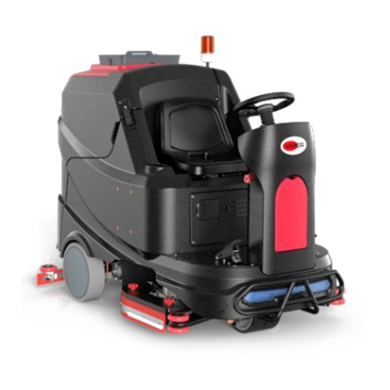
Machine General Description The AS1050R is a ride-on commercial floor scrubbing machine designed to wash and dry commercial floors. The machine is powered by on-board batteries. The machine is equipped with two single disc scrubbing brushes, a rear squeegee with vacuum suction. -
Page 6: Service And Spare Parts
Service Manual-AS1050R 03 General Information 6 Service and Spare Parts Service and repairs must be performed only by authorized personnel or Service Centers. The authorized personnel must be trained directly by the manufacturer and use original spare parts and accessories. Customers can find the Model No. -
Page 7: Safety
Service Manual-AS1050R 03 General Information 7 Safety Symbols It is important to read this manual before servicing the machine. It contains information for safety protection and preventive action. The symbols below are used to help you recognize this information. Warning:... -
Page 8: Lifting Machine
Service Manual-AS1050R 03 General Information 8 Property Damage Messages – Storage and operation temperature must be above 0° C and humidity between 30% and 95%, non-condensing. – Before use, all doors and hoods should be properly latched. – This machine is not approved for use on public paths or roads. -
Page 9: Technical Data
Service Manual-AS1050R 03 General Information 9 Technical Data Parameter Type AS1050R Voltage 36 V Rated power (input) 125A/4500W IP protection class IP24 Solution tank capacity 200L / 53 Gal. Recovery tank capacity 200L / 53 Gal. Scrubbing width 980mm / 38.58 Inches... -
Page 10: Maintenance Schedule
Service Manual-AS1050R 03 General Information 10 Maintenance Schedule CAUTION! The procedure marked with (1) must be performed when machine is used after 8 hours for the first time. The procedure marked with (2) must be done by Service Center qualified by our company. -
Page 11: Machine Structure
Service Manual-AS1050R 03 General Information 11 Machine Structure Figure 2... -
Page 12: Machine Structure (Continues)
Service Manual-AS1050R 03 General Information 12 Machine Structure (continues) Figure 3... -
Page 13: Control Panel
Service Manual-AS1050R 03 General Information 13 Control Panel Figure 4... -
Page 14: Service And Diagnostic Equipment
Service Manual-AS1050R 03 General Information 14 Service and Diagnostic Equipment Besides a complete set of standard meters, the following instruments are necessary to perform quick check and repairs on machines: Digital Voltmeter (DVM) Amp clamp with possibility of making DC measurements... -
Page 15: Dimensions (Continues)
Service Manual-AS1050R 03 General Information 15 Dimensions (continues) -
Page 16: Control System
Service Manual-AS1050R 04 Control System 16 04 Control System Functional Description • The machine utilizes a Dash Board (EB1) to turn on Battery type setting • various machine functions and a Main Controller (EB2) LED headlight (LED1&LED2) to control outputs. When Dash Board (EB1) receives... - Page 17 CAN Bus see the message but pay attention only to those messages they need to know about. The AS1050R has 2 CAN Bus Nodes as Dash Board (EB1) and Main Controller (EB2). Dash Board (EB1) receives commands from operator and then transmit this information to Main Controller (EB2) through CAN Bus to perform them accordingly.
-
Page 18: Component Locations
Service Manual-AS1050R 04 Control System 18 Component Locations • Dash Board (EB1) • Main contactor (K1) • Main Controller (EB2) • Warning lamp • USB charger (EB3) • Main ground lug Main Controller (EB2) Dash Board (EB1) Figure 2 Figure 3... -
Page 19: Removal And Installation
Service Manual-AS1050R 04 Control System 19 Removal and Installation Warning! This procedure must be performed by qualified personnel only. Park machine on level ground. Switch off machine. Dash Board (EB1) 1. Prepare necessary tools, cross screwdriver and socket spanner. 2. Remove 7 screws on Dash Board, detach Dash Board (Figure 8). - Page 20 Service Manual-AS1050R 04 Control System 20 Main Controller (EB2) 1. Prepare necessary tools, cross screwdriver. 2. Remove 4 screws on cover of electric control box, then take off cover (Figure 12). 3. Disconnect all harnesses connected to Main Controller (Figure 13).
-
Page 21: Troubleshooting
Service Manual-AS1050R 04 Control System 21 Troubleshooting Access to Panel Parameter Setting 1. Power off the machine. Press “scrub pressure +” and “scrub pressure -” button at the same time and power up the machine (Figure 1). 2. LCD will display “Input password” in 4 seconds, then release the two buttons (Figure 2). - Page 22 Service Manual-AS1050R 04 Control System 22 Confirm the password by pressing the button Figure 6 Figure 5 Press the button Figure 7...
- Page 23 Service Manual-AS1050R 04 Control System 23 Error Code List When an error message is detected by system, the LCD monitor on Dash Board will display the corresponding error number and description. After the problem is corrected, the display will be cancelled automatically. There is no history function to display error history at present.
- Page 24 Service Manual-AS1050R 04 Control System 24 1. “Error 1”: Solenoid valve short circuit or overload • Possible causes: Solenoid valve or Main Controller (EB2) or wiring short circuit. Main Controller (EB2) Solenoid valve 2. “Error 2”: Brush motor short circuit or overload •...
- Page 25 Service Manual-AS1050R 04 Control System 25 4. “Error 4”: Traction motor short circuit or overload • Possible causes: • 1. Traction motor or Main Controller (EB2) or wiring short circuit. • 2. Physical resistance to machine movement such as a dragging brake or going up a steep incline.
- Page 26 Service Manual-AS1050R 04 Control System 26 Circuit breaker (30A) (F3, F4) Brush motor Brush motor wires Brush motor wires 8. “Error 8”: Vacuum motor wiring open circuit • Check wire harness in vacuum motor and Main Controller (EB2). • Check circuit breaker (F5, F6).
- Page 27 Service Manual-AS1050R 04 Control System 27 11. “Error 11”: Need to replace traction motor carbon brush • Replace traction motor carbon brush or traction motor. • Reset traction motor runtime. 1. Refer to steps in “Access to Panel Parameter Setting” (Page 21) .
- Page 28 Service Manual-AS1050R 04 Control System 28 13. “Error 13”: Need to replace vacuum motor carbon brush • Replace vacuum motor carbon brush or vacuum motor. • Reset vacuum motor runtime. Refer to steps in “Access to Panel Parameter Setting”(Page 21).
- Page 29 Service Manual-AS1050R 04 Control System 29 16. “Error 16”: Communication wiring broken • Check if CAN communication lines are broken. • Check if order of connection of CAN communication lines is correct. • Check if Main Controller (EB2) or panel is working properly.
- Page 30 Service Manual-AS1050R 04 Control System 30 23. “Error 27”: Water pump short circuit or overload • Check if water pump wiring is short circuit. • Check if water pump is working properly. • Replace water pump. 24. “Error 28”: Squeegee actuator motor short circuit or overload •...
- Page 31 Service Manual-AS1050R 04 Control System 31 32. “Error 36”: Electromagnetic brake wiring open circuit • Check if electromagnetic brake wiring is broken. • Check if electromagnetic brake handle is opened manually. • Check if electromagnetic brake internal resistance is short circuit.
-
Page 32: Specifications
Service Manual-AS1050R 04 Control System 32 Specifications Sample Shop Voltage Measurement The following tables contain some “real world” shop voltage measurements to help you recognize what “normal” looks like. • Unless otherwise noted, all voltage readings are referenced to the main ground lug in the electrical bay. - Page 33 Service Manual-AS1050R 04 Control System 33 Dash Board (EB1) P2 Connector Pin# Color Function Condition Value Max. speed 1.5V Speed limit pot in Min. speed 0.15V BU-BK Speed limit pot high 1.5V GR-BK Speed limit pot low 0.15V ≈36V Power for MCU ≈36V...
- Page 34 Service Manual-AS1050R 04 Control System 34 Figure 2. Connectors on Main Controller (EB2) Main Controller (EB2) P1 Connector Pin# Color Function Condition Value ≈36V Inactive, Brake set Electromagnetic Brake+ ≈36V Active, Brake released ≈36V Inactive, Brake set Electromagnetic Brake- ≈2V...
- Page 35 Service Manual-AS1050R 04 Control System 35 Main Controller (EB2) P2 Connector Pin# Color Function Condition Value Raise, Ref 4 to 11 +32v Lower, Ref 4 to 11 -32v Squeegee actuator out1 +/- Squeegee actuator out2 +/- At rest, Ref 4 to 11 Turn >15 degrees...
- Page 36 Service Manual-AS1050R 04 Control System 36 Main Controller (EB2) P3 Connector Pin# Color Function Condition Value ≈13V Active Main relay(K1) PWM output ≈36V Inactive ≈36V key switch on Key switch input key switch off Main Controller (EB2) P4 Connector Pin#...
- Page 37 Service Manual-AS1050R 04 Control System 37 Dash Board (EB1) Parameter Setting NO. Parameter Name Value Unit Comment GEL-0 VOLT 30.9 GEL battery voltage at level 0 GEL-1 VOLT 32.4 GEL battery voltage at level 1 GEL-2 VOLT 33.3 GEL battery voltage at level 2 GEL-3 VOLT 34.2...
- Page 38 Service Manual-AS1050R 04 Control System 38 Dash Board (EB1) Parameter Setting Parameter Name Value Unit Comment Reserved 100% BAT Reserved Reserved 100% BAT Reserved Reserved 100% BAT Reserved Reserved 70% BAT Reserved Vac Off Delay Seconds Vacuum motor off delay time...
- Page 39 Service Manual-AS1050R 04 Control System 39 Main Controller (EB2) Parameter Setting NO. Parameter Name Value Unit Comment Load Unit Def Reserved Load Veh Set Reserved Customer ID Customer ID Device Type Reserved 0-Switch control, 1-CAN communication control (control Control Mode...
- Page 40 Service Manual-AS1050R 04 Control System 40 Main Controller (EB2) Parameter Setting NO. Parameter Name Value Unit Comment Enable alarm function when power up machine with accelerator Accel SRO being pressed. 0-Disable, 1-Enable Direction SRO Reserved Dir Lock Out Reserved Start SW SRO...
- Page 41 Service Manual-AS1050R 04 Control System 41 Main Controller (EB2) Parameter Setting NO. Parameter Name Value Unit Comment Bru Unload Rate Seconds Brush release deceleration rate Bru load Rate Seconds Brush installation acceleration rate Bru load Down T Seconds Brush installation down time...
- Page 42 Service Manual-AS1050R 04 Control System 42 Main Controller (EB2) Parameter Setting NO. Parameter Name Value Unit Comment Squ DwStop I Squeegee down stop current Bru-d TopSpeed Brush disc lifting motor maximum voltage Brd Max ADJSpd Reserved Brd Min AdjSpd Reserved BrD Up In RVS Brush disc up in reverse.
- Page 43 Service Manual-AS1050R 04 Control System 43 Main Controller (EB2) Parameter Setting NO. Parameter Name Value Unit Comment Wat-Emp ValOff Solution tank empty valve off. 0-Not off Wat-Emp BruOff Solution tank empty brush off. 0-Not off Dir-Full VavOff Recovery tank full valve off. 0-Not off Dir-Full VacOff Recovery tank full vacuum motor off.
- Page 44 Service Manual-AS1050R 04 Control System 44 Parameter Setting Without Password Some parameters in following table can be set without password. Please refer to following steps to set the parameters. Power down machine. Press “solution +” button and “solution -” button at the same time. Meanwhile power up machine. See figure below.
- Page 45 Service Manual-AS1050R 04 Control System 45 Parameter Setting Without Password NO. Parameter Name Value Unit Comment Turn Spd Decel-1 Seconds Transport Mode. Turning deceleration rate 1 Turn Spd Perc-1 Transport mode. Turning deceleration percentage 1 Turn Spd Decel-2 Seconds Transport mode. Turning deceleration rate 2 Turn Spd Perc-2 Transport mode.
-
Page 46: Chassis System
Service Manual-AS1050R 10 Chassis System 46 10 Chassis System Chassis (main parts) The chassis is attached to the bottom of solution tank. Figure 1... -
Page 47: Wheel System-Traction
Service Manual- AS1050R 14 Wheels System 47 14 Wheel System-Traction Functional Description The traction motor (M1) drives the rear wheels of machine to propel it. The speed limit potentiometer (VR1) enables operator to adjust the maximum forward and reverse speed of machine at its full throttle. -
Page 48: Wiring Diagram
Service Manual- AS1050R 14 Wheels System 48 Wiring Diagram Traction System Wiring Diagram (Only For TIGER3) EB1 Dash Board EB2 Main Controller BAT+ P1-4 P3-18 BAT+ Key Switch +36V Input P1-2 P4-2 FUSE 200A CAN H CAN H 120 Ohm... -
Page 49: Component Locations
Service Manual- AS1050R 14 Wheels System 49 Component Locations Speed limit potentiometer (VR1) Seat switch (SW7) Throttle pedal Main Controller (EB2) Brake sensor switch (SW6) Speed limit potentiometer (VR1) Throttle pedal Figure 2 Figure 3... -
Page 50: Component Locations (Continues)
Service Manual- AS1050R 14 Wheels System 50 Component Locations (continues) • Electromagnetic brake (KA1) • Traction motor (M1) • Proximity sensor (SQ1 & SQ2) Electromagnetic brake (KA1) Traction motor (M1) Figure 6 Proximity sensor (SQ1) Proximity sensor (SQ2) Figure 7... -
Page 51: Removal And Installation
Service Manual- AS1050R 14 Wheels System 51 Removal and Installation Traction Motor (M1) Removal Drain recovery tank. Drain solution tank. Remove brush. Remove squeegee. Remove machine’s batteries. Raise rear wheel off ground with jack (A) and support with adequate blocking (Figure 8). - Page 52 Service Manual- AS1050R 14 Wheels System 52 Front Wheels Removal Park machine on level ground. Switch off machine. Lift front wheels about 2cm off ground to enable wheels to turn freely. Use supporting tool jack (A) and adequate blocking (B) to support machine.
- Page 53 Service Manual- AS1050R 14 Wheels System 53 Rear Wheels Removal Park machine on level ground. Switch off machine. Lift rear wheel about 1cm off ground to enable it to turn freely. Use supporting tool jack (F) and adequate blocking to support machine.
-
Page 54: Troubleshooting
Service Manual- AS1050R 14 Wheels System 54 Troubleshooting Possible causes Trouble Remedy Traction motor wire connection fault Check wire harness Traction motor fault Check motor amperage/check motor resistance /replace motor Driving wheel controller fault Check Main Controller (EB2) wire harness/replace Main Controller (EB2) The machine can’t move... - Page 55 Service Manual- AS1050R 14 Wheels System 55 Traction Motor Amperage Check Warning! This procedure must be performed by qualified personnel only. Park machine on level ground. Lift traction motor about 2cm off ground so that it can turn freely. Warning! Pay attention to the rotation of driving wheel when performing following steps.
-
Page 56: Specifications
Service Manual- AS1050R 14 Wheels System 56 Specifications Description Unit Value Traction Motor Rated Input Power 1600 Traction Motor Rated Input Voltage Traction Motor Rated Input Current Traction Motor Allowed Over Current (less than 1 minute) Traction Motor Normal Current (traction motor lifted) Ω... -
Page 57: Electrical System
AS1050R Service Manual- 24 Electrical System 57 24 Electrical System Functional Description The batteries (3 x 12V or 6 x 6V) are connected in series. When an external charger is inserted, charger sensor switch (SW3) will close. If key switch is on at this time, LCD will be off. -
Page 58: Wiring Diagram
AS1050R Service Manual- 24 Electrical System 58 Wiring Diagram TIGER3 Electrical System Dash Board Main Controller P1-4 P3-18 Key Switch P6-1 USB Charger P6-2 P1-1 RD/BK P6-3 Key Switch Emergency Stop P6-4 P2-5 MCU VDD Circuit Breaker 5A C3-1 RD/BK... -
Page 59: Component Locations
AS1050R Service Manual- 24 Electrical System 59 Component Locations • Dash Board (EB1) • External charger connector (C5) • Battery (BAT) • Key switch (SW2) • Battery connector • Emergency switch (SW1) • Dash Board circuit breaker (5A) (F1) • Charger sensor switch (SW3) -
Page 60: Maintenance And Adjustment
AS1050R Service Manual- 24 Electrical System 60 Maintenance and Adjustment Setting Installed Battery Type Set battery type on control panel according to different battery types (WET, GEL, AGM, DIS-EV or ENE) following steps below: 1. Turn off machine. 2. Press flow adjusting buttons “+” and “-” (E, F, Figure 8). -
Page 61: Removal And Installation
AS1050R Service Manual- 24 Electrical System 61 Removal and Installation Warning Lamp Removal Remove 2 screws (A) Remove 4 screws (B) and 4 cable cleats (C). Remove connectors (D). Remove warning lamp assembly. Installation Assemble components in reverse order of disassembly. - Page 62 AS1050R Service Manual- 24 Electrical System 62 Installation Assemble components in reverse order of disassembly. Gantry Machine Figure 11...
-
Page 63: Troubleshooting
AS1050R Service Manual- 24 Electrical System 63 Troubleshooting Key switch (SW2) is damaged Repair/replace Circuit breaker (F1) is opened Reset circuit breaker Machine can’t be turned on Emergency switch (SW1) is opened or damaged Close SW1/repair/replace Charger sensor switch (SW3) is activated... - Page 64 AS1050R Service Manual- 24 Electrical System 64 Connector Pinouts Dash Board (EB1) P1&P5 Connector Pin# Name Color Ground CAN-H CAN-L Power Input 36V Dash Board (EB1) P2 Connector Pin# Name Color Speed limit pot in Speed limit pot high BLU-BLK...
- Page 65 AS1050R Service Manual- 24 Electrical System 65 Dash Board (EB1) P3 Connector Pin# Name Color Headlight power + output Headlight power - output Dash Board (EB1) P4 Connector Pin# Name Color Buzzer power + output Buzzer power - output Dash Board (EB1) P6 Connector...
- Page 66 AS1050R Service Manual- 24 Electrical System 66 Dash Board (EB1) P7 Connector Pin# Name Color SQ2 Proximity sensor +Power SQ1 Proximity sensor +Power SQ1 Proximity sensor SQ2 Proximity sensor Main Controller (EB2) P1 Connector Pin# Name Color Electromagnetic Brake+ Electromagnetic Brake-...
- Page 67 AS1050R Service Manual- 24 Electrical System 67 Main Controller (EB2) P2 Connector Pin# Name Wire Color 36V Output Water pump PWM output Brush deck actuator out1 +/- Squeegee actuator out1 +/- Slow down sensor 1 input Pedal inner relay switch in...
- Page 68 AS1050R Service Manual- 24 Electrical System 68 Harness to Harness Connector Locations This chapter mainly marks the locations of harness to harness connectors that are not easy to find for the convenience of technicians. • Harness to Harness Connectors C15 (Left Brush Motor), C18 (Brush Deck Actuator).
- Page 69 AS1050R Service Manual- 24 Electrical System 69 • Harness to Harness Connectors C12 (Pedal). • Harness to Harness Connectors C8 (Solution sensor). • Harness to Harness Connectors C6 (Slow Down Sensor 2), C7 (Slow Down Sensor 1).
- Page 70 AS1050R Service Manual- 24 Electrical System 70 • Harness to Harness Connectors C9 (Recovery Sensor, Power for Warning Light) • Harness to Harness Connectors C13 (Electromagnetic Brake), C19 (Squeegee Actuator)
-
Page 71: Electrical Wiring Diagram
AS1050R Service Manual- 24 Electrical System 71 Electrical Wiring Diagram Main Controller Dash Board P1-2 P4-2 CAN-H CAN-H Traction+ 120 Ohm 120 Ohm P1-3 P4-3 CAN-L CAN-L P1-4 P3-18 Traction Motor Key Switch Traction- P1-1 P6-1 RD/BK USB Charger C13-1... -
Page 72: Solution System
AS1050R Service Manual- 30 Solution System 72 30 Solution System Functional Description The solution system supplies water to the brush when The water pump (M8) and solution valve (EV1) can only cleaning the floor. The solution tank is also the main operate when all following inputs/conditions are met: ... -
Page 73: Component Locations
AS1050R Service Manual- 30 Solution System 73 Component Locations • Solution valve (EV1) • Water pump (M8) • Solution sensor (SW4) Solution valve (EV1) Water pump (M7) Figure 2 Figure 3 Solution sensor (SW4) Figure 4... -
Page 74: Maintenance And Adjustment
AS1050R Service Manual- 30 Solution System 74 Maintenance and Adjustment Solution Filter Cleaning 1. Park machine on level ground. 2. Ensure that machine is off, and ignition key has been removed. 3. Turn the valve (A, Figure 5) to off “0”. -
Page 75: Removal And Installation
AS1050R Service Manual- 30 Solution System 75 Removal and Installation Solenoid Valve (EV1) Removal 5. Disconnect hoses (A, B) from solenoid valve (C). 6. Disconnect electrical connectors (D) on solenoid valve (C). 7. Remove hex screw (E), then remove plain washer (F) and spring washer (G). -
Page 76: Troubleshooting
AS1050R Service Manual- 30 Solution System 76 Troubleshooting Trouble Possible causes Remedy Solution filter is clogged/full of dirt Clean Solenoid valve fault or electrical connector Replace solenoid valve or repair damaged electrical connector There is dust/debris in the tank or in the detergent... -
Page 77: Specifications
AS1050R Service Manual- 30 Solution System 77 Specifications Description Unit Value Solution tank capacity Solution flow values Liters/Min 1.6/2.3/3.3/4.6 Ω Solution solenoid coil resistance @25℃ Water pump maximum input current Water pump rated voltage... -
Page 78: Scrub System
AS1050R Service Manual- 34 Scrub System 78 34 Scrub System Functional Description The brush system is controlled by operator. The rotating brush system can clean the surface of floor. The main component of brush system is the deck where brushes or pad holders with pads suitable for the type of floor to be cleaned are installed. -
Page 79: Wiring Diagram
AS1050R Service Manual- 34 Scrub System 79 Wiring Diagram TIGER3 Scrub System Dash Board Main Controller BAT+ BAT+ +36V Input P1-2 P4-2 CAN H CAN H BAT- BAT- 120 Ohm 120 Ohm P1-3 P4-3 CAN L CAN L P1-4 P3-18... -
Page 80: Brush Deck Actuator System
AS1050R Service Manual- 34 Scrub System 80 Brush Deck Actuator System The brush deck actuator (M6) is controlled directly by the Main Controller (EB2). When the machine is turned on the actuator is powered to move upwards for several seconds until the cam on the actuator opens the travel limit switch, giving it time to reach the fully retracted position. -
Page 81: Component Locations
AS1050R Service Manual- 34 Scrub System 81 Component Locations • • Brush deck actuator circuit breaker (3A) (F7) Brush motors (M2&M3) • • Brush deck actuator (M6) Brush deck • Brush circuit breakers (30A) (F3&F4) Brush circuit breakers (30A) (F3&F4) Brush motors (M2&M3) -
Page 82: Removal And Installation
AS1050R Service Manual- 34 Scrub System 82 Removal and Installation Brush Deck Actuator Removal 1. Remove brushes and skirts. 2. First pull out spring (A) and (B). 3. Put down brush deck (C). 4. Pull out pin (D), then take out shaft (E). - Page 83 AS1050R Service Manual- 34 Scrub System 83 Brush Motor Carbon Brushes Removal Remove brush deck (see procedures in relevant paragraph); don’t disconnect brush motor electrical connection. Remove screws (A) and protection strip (B) of brush motor (C). For all four motor’s carbon brushes, disengage spring (D) and remove carbon brush (E) from its seat, then detach the carbon brush by disengaging its electrical connection (F).
- Page 84 AS1050R Service Manual- 34 Scrub System 84 Brush Motor (M2&M3) Removal 1. Remove brushes and skirts. 2. Remove bolts (A), then remove connection plate (B) and (C). 3. Remove bolts (D). 4. Cut off nylon cable tie (E) and (F), unplug connector (H) and (G).
-
Page 85: Maintenance And Adjustment
AS1050R Service Manual- 34 Scrub System 85 Maintenance and Adjustment Side Squeegee Blade Changing The left and right squeegee blades need to be changed periodically. The blades can be flipped or reversed to a new edge for up to 3 times before replacement is required. During replacement, it is important that the blades be installed flat without waves and adjusted to be laid flat against the floor. - Page 86 AS1050R Service Manual- 34 Scrub System 86 Loosen the butterfly nut (C), then take out the carriage screw (D). Take off the side blade strap (E). Then take off the rubber side blade (F). Remove the rubber side blade (F) and switch it to the other side or exchange the left and right side.
-
Page 87: Troubleshooting
AS1050R Service Manual- 34 Scrub System 87 Troubleshooting Possible causes Trouble Remedy Brush does not clean Brush is excessively worn Replace properly Brush motor carbon brushes worn Replace Presence of mass debris or strings around Remove brush and clean it... - Page 88 AS1050R Service Manual- 34 Scrub System 88 Brush Motor Amperage Check Warning! This procedure must be performed by qualified personnel only. Park machine on level ground. Remove brushes. Apply amp clamp (A, Figure 10) to one of the motor wires (B, Figure 10).
-
Page 89: Specifications
Service Manual- AS1050R 34 Scrub System Specifications Description Unit Value Cleaning width in (mm) 49.2 (1250) Brush motors power hp (W) 1.5*2 (1000*2) Brush rotation speed (normal mode) Brush rotation speed (ECO mode) Brush motors insulation class Brush motors current (no brushes) -
Page 90: Squeegee System
Service Manual- AS1050R 38 Squeegee System 38 Squeegee System Functional Description the squeegee actuator will rise automatically. When the The squeegee system cleans the liquid on the floor, which machine moves backward, if the squeegee is not in the is then collected by the recovery system. - Page 91 Service Manual- AS1050R 38 Squeegee System Component Locations • Squeegee actuator (M7) • Mounting handwheel • Impact deflection wheel • Squeegee blade Impact deflection wheel Squeegee blade Mounting handwheel Figure 2 Squeegee actuator (M7) Figure 3...
- Page 92 Service Manual- AS1050R 38 Squeegee System Maintenance and Adjustment Squeegee Blade Changing The front and back squeegee blades need to be changed periodically. The blades can be flipped or reversed to a new edge for up to 3 times before replacement is required. During replacement, it is important that the blades be installed flat without waves and adjusted to be laid flat against the floor.
- Page 93 Service Manual- AS1050R 38 Squeegee System Open latch (D) to release retaining strap. Take off hook (E). Take off rear strap (G). Remove rear squeegee blade (H) and switch it to the other side. The squeegee blade can be rotated and/or flipped for 3 times to expose a new edge (4 edges total) to the lower front.
- Page 94 Service Manual- AS1050R 38 Squeegee System Loosen clamping thumbscrew (P) on front strap (L) and remove strap from frame. Remove front squeegee blade (M) and switch it to the other side. – The squeegee can be rotated and/or flipped for 3 times to expose a new edge (4 edges total) to the lower front.
- Page 95 Service Manual- AS1050R 38 Squeegee System Squeegee Trim Adjustment The squeegee trim adjustment ensures that the squeegee frame is level with the floor when the squeegee is in the lowered, operating position. If the trim is out of adjustment, either the center or the edges of the squeegee will leave streaks of water on the floor.
- Page 96 Service Manual- AS1050R 38 Squeegee System 96 Removal and Installation Squeegee Bracket Removal Drain recovery tank. Drain solution tank. Remove brushes. Remove squeegees. Remove machine’s batteries. Raise machine. First pull out spring (A) and (B). Pull out pin (C), then take out shaft (D).
- Page 97 Service Manual- AS1050R 38 Squeegee System 97 Squeegee Actuator Removal Pull out spring (F) and (G). Take out shaft (I), then remove brass bushing (H). Pull out pin (J), then take out shaft (K). Take out actuator (L). Installation Assemble components in reverse order of disassembly.
- Page 98 Service Manual- AS1050R 38 Squeegee System 98 Troubleshooting Trouble Possible causes Remedy Vacuum suction is insufficient Squeegee or vacuum hose is clogged or damaged Clean or repair/replace or no vacuum suction There is debris under the blade Remove Squeegee blade edges are torn or worn...
- Page 99 AS1050R Service Manual- 40 Recovery System 99 40 Recovery System Functional Description The recovery system removes dirty water from the The vacuum system is activated automatically by the floor and pumps it to the recovery tank. When machine one-touch button and it can then be managed via the is running, dirty water on the floor is collected through vacuum button independently.
- Page 100 AS1050R Service Manual- 40 Recovery System 100 Component Locations • Squeegee actuator (M7) • Recovery sensor (SW5) • Squeegee actuator circuit breaker (3A) (F8) • Vacuum motor connecting terminals • Vacuum motor circuit breaker (30A) (F5&F6) Squeegee actuator circuit breaker (3A) (F8) Squeegee actuator (M7) Vacuum motor circuit breaker (30A) (F5&F6)
- Page 101 AS1050R Service Manual- 40 Recovery System 101 Removal and Installation Vacuum System Motor (M4) Removal 1. Drain recovery tank. Turn ignition key to “0” and remove it. Make sure that machine won’t move by itself. Tip back recovery tank, then disconnect battery connector.
- Page 102 AS1050R Service Manual- 40 Recovery System 102 Vacuum Motor Carbon Brushes Removal The vacuum motor brush is a quick-wear item that should be inspected and replaced periodically. 1. Make sure solution tank and recovery tank are empty. Excess weight in the tanks can throw off the balance of machine when scrubbing deck is removed from machine.
- Page 103 AS1050R Service Manual- 40 Recovery System 103 7. Press the retaining tab (G) and slide the brush wire (F) out of the brush holder. 8. Slide brush (H) out of the rear of brush holder (D). Make sure brush length >9mm.
-
Page 104: Recovery Tank And Seals
AS1050R Service Manual- 40 Recovery System 104 Maintenance and Adjustment Recovery Tank and Seals Park machine on level ground. 2. Ensure that machine is off, and ignition key has been removed. 3. Open recovery tank lid (A, Figure 9) and make sure the support (B) is working properly. -
Page 105: Cleaning The Recovery Tank
AS1050R Service Manual- 40 Recovery System 105 Cleaning the Recovery Tank Park machine on level ground. Turn ignition key (A) to "0". Open recovery tank (B) and recovery tank lid (C). Remove debris collection box (D) from recovery tank and clean it up. -
Page 106: Troubleshooting
AS1050R Service Manual- 40 Recovery System 106 Troubleshooting Possible causes Trouble Remedy Wiring damaged Repair/replace Main Controller (EB2) fault Replace The vacuum motor Vacuum motor damaged Check the amperage/replace can’t be turned on Recovery sensor (SW5) is activated Drain the recovery tank... -
Page 107: Specifications
AS1050R Service Manual- 40 Recovery System 107 Specifications Description Value Recovery tank capacity 200L 600W Vacuum motor technical data DC 36V Maximum vacuum circuit capacity 62 in H2O (1575 mm H2O) (normal mode/single motor) Vacuum circuit capacity 50 in H2O (1270 mm H2O)
Need help?
Do you have a question about the AS1050R and is the answer not in the manual?
Questions and answers