Table of Contents
Advertisement
Available languages
Available languages
Quick Links
- Istruzioni per bruciatori modello
- Instruction for burners model
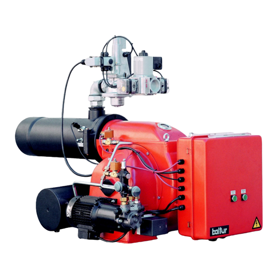
COMIST 122 N
Prima di iniziare a usare il bruciatore leggere attentamente
quanto esposto nel capitolo "AVVERTENZE PER
L ' U T E N T E , P E R L' U S O I N S I C U R E Z Z A D E L
BRUCIATORE" presente all'interno del manuale istruzioni,
che costituisce parte integrante ed essenziale del prodotto.
Edizione / Edition
Cod. 0006080113
it
en
2004/10
Advertisement
Table of Contents

Subscribe to Our Youtube Channel
Related Manuals for baltur COMIST 122 N


Summary of Contents for baltur COMIST 122 N
- Page 1 - Istruzioni per bruciatori modello - Instruction for burners model COMIST 122 N Prima di iniziare a usare il bruciatore leggere attentamente 2004/10 quanto esposto nel capitolo “AVVERTENZE PER Edizione / Edition L ’ U T E N T E , P E R L’ U S O I N S I C U R E Z Z A D E L BRUCIATORE”...
- Page 3 IT - Leggere attentamente le istruzioni prima di mettere in funzione il bruciatore o di eseguire la manutenzione. - I lavori sul bruciatore e sull’impianto devono essere eseguiti solo da personale qualificato. - L’alimentazione elettrica dell’impianto deve essere disinserita prima di iniziare i lavori. - Se i lavori non sono eseguiti correttamente si rischiano incidenti pericolosi.
- Page 4 Normes CE – CEI – UNI en vigueur au moment de la fabrication. • La BALTUR garantit la certification “CE” seulement si les brûleur sont installé avec les rampes de gaz “CE” produites par la BALTUR et les accessoires de ligne gaz “CE” (fournis sur demande).
-
Page 5: Avvertenze Per L'utente Per L'uso In Sicurezza Del Bruciatore
L’eventuale riparazione dei prodotti dovrà essere effettuata solamente da un centro di assistenza autorizzato dalla BALTUR utilizzando esclusivamente ricambi originali. Il mancato rispetto di quanto sopra, può compromettere la sicurezza dell’apparecchio. Per garantire l’efficienza dell’ apparecchio e per il suo corretto funzionamento é indispensabile fare effettuare da personale professionalmente qualificato la manutenzione periodica attenendosi alle indicazioni del costruttore. - Page 6 AVVERTENZE PER L’UTENTE PER L’USO IN SICUREZZA DEL BRUCIATORE ALIMENTAZIONE ELETTRICA • La sicurezza elettrica dell’apparecchio è raggiunta soltanto quando lo stesso è corretamente collegato a un’efficace impianto di messa a terra, eseguito come previsto dalle vigenti norme di sicurezza (D.P.R. 547/55 art. 314). E’ necessario verificare questo fondamentale requisito di sicurezza. In caso di dubbio, richiedere un controllo accurato dell’impianto elettrico da parte di personale professionalmentequalificato, poiché...
- Page 7 CARATTERISTICHE TECNICHE / N° 0002570151 TECHNICAL DATA / REV: 20/10/2004 CARACTERISTICAS TECNICAS MODELLO / MODEL / MODELO COMIST 122 N 1364 POTENZA TERMICA / THERMIC CAPACITY / POTENCIA TÉRMICA m³/h PORTATA / FLOW RATE / CAUDAL m³/h TRASFORMATORE METANO / NAT. GAS TRANSFORMER...
- Page 8 CARATTERISTICHE TECNICHE / N° 0002570151 TECHNICAL DATA / REV: 20/10/2004 CARACTERISTICAS TECNICAS - Pressostati gas - Gas Pressure switches - Fotoresistenza - Photoresistance - Pressostato aria - Air pressure switch - Servomotore regolazione aria - Air regulation servomotor - Valvola gas di sicurezza - Safety gas valve - Valvola gas di funzionamento - Main gas valve...
-
Page 9: Collegamenti Elettrici
ITALIANO FISSAGGIO DEL BRUCIATORE ALLA CALDAIA (flangia di fissaggio in acciaio) 1 - Piastra caldaia 2 - Flangia in materiale isolante 5 - Prigioniero 6 - Dado e rondella di bloccaggio 3 - Flange fissaggio bruciatori 7 - Dado e rondella fissaggio prima flangia 4 - Collare elastico Nota: Il bruciatore è... - Page 10 ITALIANO SCHEMA DI PRINCIPIO PER L'INSTALLAZIONE IMPIANTO DI ALIMENTAZIONE GAS SARACINESCA-FILTRO-STABILIZZATORE- A BASSA PRESSIONE ( max. 400 mm.C.A.) GIUNTO ANTIVIBRANTE-RACCORDO APRIBILE Devono essere installati: rubinetto a sfera di intercettazione, filtro gas, stabilizzato- re di pressione oppure (quando la pressione di alimenta- zione è...
- Page 11 SCHEMA DI PRINCIPIO PER IL COLLEGAMENTO DI PIÙ’ N° BT 8530/1 BRUCIATORI ALLA RETE GAS A MEDIA PRESSIONE REV: 15/11/1990 1 - Centralina di riduzione e misura 2 - Rubinetto di intercettazione 3 - Filtro gas 4 - Riduttore di pressione 5 - Contatore 6 - Rubinetto di intercettazione di emergenza (installato all'esterno) 7 - Rubinetto a sfera...
-
Page 12: Pompa Ausiliaria
TUBAZIONE DEL COMBUSTIBILE (Olio Combustibile) L’esposizione che segue tiene esclusivamente conto di quanto necessario per assicurare un buon funzionamento. L’apparecchio è dotato di pompa auto-aspirante capace quindi di aspirare direttamente l’olio dalla cisterna anche per il primo riempimento. Questa affermazione è valida purché sussistano i presupposti necessari, (consultare la tabella relativa alle distanze e ai dislivelli e il diagramma viscosità... - Page 13 SCHEMA IDRAULICO DI PRINCIPIO ALIMENTAZIONE PER PIÚ BRUCIATORI BT 8666/3 DI GASOLIO OPPURE OLIO COMBUSTIBILE CON VISCOSITÁ NOMINALE REV:02/10/2002 MASSIMA (5° E a 50° C) 1 - Cisterna principale 2 - Filtro 3 - Pompa di circolazione 4 - Scarico acqua ed impianto 5 - Scarico aria-gas normalmente chiusa 6 - Recupero combustibile...
- Page 14 TABELLA TUBAZIONI PER BRUCIATORE MODELLO COMIST 122 N con combustibile da 5° E a 50° C (alla temperatura di pompaggio di 5° C) IMPIANTO DI ALIMENTAZIONE PER GRAVITÀ 1 Serbatoio 6 Tubo di aspirazione 2 Tubazione di alimentazione 7 Tubo ritorno bruciatore...
- Page 15 Si consiglia di effettuare per prima l’accensione con il combustibile liquido perché l’erogazione è, in questo caso, condizionata dall’ugello utilizzato, mentre, l’erogazione del gas metano può essere variata a piacimento agendo sul relativo regolatore di portata. DESCRIZIONE DEL FUNZIONAMENTO DI BRUCIATORI A DUE FIAMME MODELLO COMIST 122 N CON OLIO COMBUSTIBILE (Vedi BT 8726/1) Durante la fase di preriscaldamento dell’olio combustibile la tensione attraversa il termostato di regolazione del...
- Page 16 Nota: Da quanto sopra esposto risulta evidente che la scelta degli ugelli, in funzione della portata totale (2 ugelli in funzione) desiderata, deve essere effettuata tenendo conto dei valori di portata corrispondenti alla pressione di lavoro di 25 bar. Occorre però tenere presente che, quando il bruciatore lavora con la sola prima fiamma inserita, l’erogazione del combustibile del primo ugello è...
- Page 17 POMPA BALTUR MODELLO BT..N° 0002900580 Attacco vuotometro 1/4” Aspirazione Ritorno Targa pompa Mandata (ugello) Attacco manometro 1/4” Regolazione pressione pompa (20 ÷ 22 bar) Sede elemento riscaldante Attacco vuotometro 1/4” Aspirazione Ritorno Mandata (ugello) Regolazione pressione pompa (20 ÷ 22 bar) Attacco manometro 1/4”...
- Page 18 DESCRIZIONE DEL FUNZIONAMENTO CON GAS (METANO) L’apparecchiatura relè ciclico) di comando e controllo del bruciatore viene inserita attraverso l’interruttore del quadro ( I ). Caratteristiche apparecchiatura Apparecchiatura Tempo di Tempo di Pre-accensione Post-accensione Tempo fra 1° e relativo sicurezza preventilazione a in secondi in secondi fiamma e 2°...
- Page 19 PRIMO RIEMPIMENTO TUBAZIONE Dopo aver controllato che i tappi di protezione in plastica posti dentro gli attacchi della pompa siano stati asportati, si procede come segue: 1) Portare nella posizione “0” l’interruttore posto sul bruciatore. Questa operazione ha lo scopo di evitare l’inserzione automatica del bruciatore ed in particolare, evita l’inserzione delle resistenze che, funzionando con serbatoio vuoto potrebbero bruciare.
-
Page 20: Regolazione Dell'aria Sulla Testa Di Combustione
Per l’accensione si procede come segue: 1) Togliere, se già esistente il collegamento del termostato per impedire l’inserzione della 2° fiamma. 2) Aprire leggermente il regolatore dell’aria, per consentire il flusso d’aria che si presume necessario per il funziona- mento del bruciatore con la 1° fiamma (vedi BT 8653/1). Regolare in una posizione intermedia il dispositivo di regolazione dell’aria sulla testa di combustione (vedere il capitolo “Regolazione dell’aria sulla testa di combustio- ne e BT 8608/1). - Page 21 Riducendo il passaggio dell’aria sulla testa di combustione, occorre evitarne la chiusura completa. Provvedere alla perfetta centratura rispetto al disco. Precisiamo che se manca la perfetta centratura rispetto al disco si potrebbe verificare cattiva combustione ed eccessivo riscaldamento della testa con conseguente rapido deterioramento. La verifica si effettua guardando dalla spia posta sulla parte posteriore del bruciatore, successivamente, stringere a fondo le viti che bloccano la posizione del dispositivo di regolazione dell’aria sulla testa di combustione.
- Page 22 FOTOCELLULA UV Una leggera untuosità compromette fortemente il passaggio dei raggi ultravioletti attraverso il bulbo della fotocellula UV impedendo che l’elemento sensibile interno, riceva la quantità di radiazione necessaria per un corretto funziona- mento. Nel caso di imbrattamento del bulbo con gasolio, olio combustibile ecc., è indispensabile pulire adeguatamen- te.
-
Page 23: Installazione
VARIANTE PER BRUCIATORE PROVVISTO DI PRERISCALDATORE A VAPORE DELL’OLIO COMBUSTIBILE Il bruciatore può essere provvisto di preriscaldatore dell’olio combustibile funzionante a vapore che consente di riscaldare il combustibile con il vapore risparmiando quindi energia elettrica. Detto dispositivo è costituito da un piccolo serbatoio in cui circola il vapore, internamente allo stesso c’è... -
Page 24: Accensione E Regolazione A Gas (Metano)
N° BT 8576 SCHEMA DI PRINCIPIO PRERISCALDATORE A VAPORE INSERITO A MONTE DI QUELLO ELETTRICO REV.: 04/10/2002 1 - SARACINESCA 11- TERMOSTATO DI REGOLAZIONE PRERISCALDATORE 2 - INDICATORE DI PASSAGGIO CONDENSA 12- TERMOMETRO 3 - SCARICATORE DI CONDENSA 13 - TAPPO PER ATTACCO MANOMETRO 4 - FILTRO VAPORE 14 - PRERISCALDATORE A VAPORE 5 - SARACINESCA DI BY-PASS A COMANDO MANUALE,... - Page 25 6) Con l’interruttore del quadro bruciatore in posizione “0” ed interruttore generale inserito, verificare, chiudendo manualmente il teleruttore, che il motore giri nel senso corretto, se necessario, scambiare di posto due cavi della linea che alimenta il motore per invertire il senso di rotazione. 7) Applicare un manometro con scala adeguata (se l’entità...
- Page 26 quando il bruciatore lavora con una più elevata erogazione di combustibile. Modificando la posizione del disco fiamma occorre, normalmente, correggere anche le posizioni della serranda di regolazione aria della 1° e della 2° fiamma e, successivamente, verificare che l’accensione avvenga correttamen- 17) Il pressostato aria ha lo scopo di mettere in sicurezza (blocco) l’apparecchiatura se la pressione dell’aria non è...
-
Page 27: Manutenzione
REGOLAZIONE DELL’ARIA SULLA TESTA DI COMBUSTIONE (Vedi BT 8608/1) La testa di combustione è dotata di dispositivo di regolazione, in modo da chiudere (spostare in avanti) o aprire (spostare indietro) il passaggio dell’aria tra il disco e la testa. Si riesce così ad ottenere, chiudendo il passaggio, un’elevata pressione a monte del disco anche per le portate basse. - Page 28 N° 8875 ISTRUZIONI REGOLAZIONE VALVOLE GAS mod. MVD ... e MVDLE ... Rev. 06/11/90 La valvola gas mod. MVD è ad apertura e chiusura rapi- Mod. MVD..da. Per regolare la portata del gas, togliere svitando, la calotta "A" e allentare il dado "B". Agire con un cacciavite sulla vite "C".
-
Page 29: Principio Di Funzionamento
N° 8877 ISTRUZIONI REGOLAZIONE VALVOLA GAS mod. ZRDLE Rev. 06/11/90 PRINCIPIO DI FUNZIONAMENTO Questa valvola è a due posizioni di apertura ed è prov- vista di regolatore del punto di intervento del freno idrau- lico che determina lo scatto rapido di apertura per la prima posizione. -
Page 30: Funzionamento
ISTRUZIONI REGOLAZIONE VALVOLA GAS N° 8880 mod. SKP 10.110 B27 - SKP10.111B27 Rev. 06/11/90 AD UNO STADIO FUNZIONAMENTO Valvole ad uno stadio In caso di segnale di apertura della valvola, la pompa si inserisce e la valvola magnetica si chiude. La pompa trasfe- risce il volume di olio situato sotto il pistone nella parte superiore dello stesso, il pistone si muove verso il basso e comprime la molla di richiamo di chiusura attraverso lo stelo ed il piattello, la valvola resta in posizione di apertura, la pompa e la valvola magnetica restano sotto tensione. - Page 31 ISTRUZIONI REGOLAZIONE VALVOLA GAS N° 8881 modello SKP 10.123A27 a due stadi Rev. 06/11/90 ESECUZIONE Servomotore Il sistema di comando oleoidraulico è costituito da un cilindro pieno di olio e da una pompa oscillante con pistone di spinta. E’ prevista inoltre una elettrovalvola tra la camera di aspirazione e quella di spinta della pompa, per la chiusura. Il pistone si sposta su un giunto di tenuta inserito in un cilindro che nello stesso tempo separa idraulicamente la camera di aspirazione da quella di mandata.
- Page 32 ISTRUZIONI PER VALVOLE GAS TIPO: N° 0002910370 VE 4000A1 ( ...A...= Apertura - Chiusura, rapida) Rev. 13/10/95 Le valvole VE 4000A1 sono valvole a solenoide in classe A, normalmente chiuse. Possono essere utilizzate come valvole di intercettazione nelle rampe di alimentazione con Gas Natu- rale, Gas Manufatturato oppure GPL, su bruciatori o impianti di combustione.
- Page 33 VALVOLA GAS COMBINATA (monoblocco) N° 0002910580 mod. MB-ZRDLE 415 B01 S22 (1"1/2) / Rev. 25/01/2000 MB-ZRDLE 420 B01 S22 (2") LEGENDA 10 - Pressostato di minima pressione gas - Coperchio di accesso alla regolazione (5 ÷ 120 mbar); scatto rapido iniziale; 11 - Collegamento elettrico pressostato di minima;...
-
Page 34: Caratteristiche Tecniche
VALVOLA GAS COMBINATA (monoblocco) N° 0002910580 mod. MB-ZRDLE 415 B01 S22 (1"1/2) / Rev. 25/01/2000 MB-ZRDLE 420 B01 S22 (2") CARATTERISTICHE TECNICHE Pressione d'esercizio MAX 360 mbar (36 kPa) Pressione d'uscita (Pa): MB ..S20 / S22 = 4÷32 mbar MB .. - Page 35 VALVOLA GAS COMBINATA (monoblocco) N° 0002910580 mod. MB-ZRDLE 415 B01 S22 (1"1/2) / Rev. 25/01/2000 MB-ZRDLE 420 B01 S22 (2") Il monoblocco DUNGS modello MB-ZRDLE B01 ... S.. è costituito da: a) Pressostato di minima pressione gas (10) regolabile da 5 a 120 mbar b) Filtro gas (8) c) Regolatore (stabilizzatore) di pressione (7) d) Valvola di sicurezza (incorporata nel regolatore di pressione) ad apertura e chiusura rapida (9)
-
Page 36: Apparecchiatura Di Comando E Controllo
APPARECCHIATURA DI COMANDO E CONTROLLO N° 7451 PER BRUCIATORI A GAS LFL 1.333 serie 02 Rev. 07/1996 Apparecchi di comando e controllo per bruciatori ad aria soffiata da medie a grandi potenzialità (a servizio intermittente *) per bruciatori a 1 o 2 stadi o modulanti con supervisione della pressione dell’aria per il co- mando della serranda aria. - Page 37 APPARECCHIATURA DI COMANDO E CONTROLLO N° 7451 PER BRUCIATORI A GAS LFL 1.333 serie 02 Rev. 07/1996 Collegamenti elettrici Per il collegamento della valvola di sicurezza vale lo schema del produttore del bruciatore Legenda per l’intero foglio di catalogo Termostato o pressostato Contatto commutatore di fine corsa per Valvola del combustibile a regolazione continua la posizione APERTA della serranda aria...
- Page 38 APPARECCHIATURA DI COMANDO E CONTROLLO N° 7451 PER BRUCIATORI A GAS LFL 1.333 serie 02 Rev. 07/1996 Note sul programmatore sequenza del programmatore segnali in uscita sulla morsettiera Legenda tempi tempi (50 Hz) in secondi 31,5 Tempo di pre-ventilazione con serranda aria aperta Tempo di sicurezza Tempo di sicurezza o primo tempo di sicurezza con bruciatori che utilizzano bruciatori pilota Tempo di pre-accensione corto (trasformatore di accensione sul morsetto 16)
- Page 39 APPARECCHIATURA DI COMANDO E CONTROLLO N° 7451 PER BRUCIATORI A GAS LFL 1.333 serie 02 Rev. 07/1996 t2´, t3´, t4´: Questi intervalli sono validi solo per gli apparecchi di comando e controllo bruciatore serie 01, ovvero LFL1.335, LFL1.635, LFL1.638. Non valgono per i tipi della serie 02 in quanto prevedono un azionamento contemporaneo delle camme X e VIII. Funzionamento Gli schemi sopra riprodotti illustrano sia il circuito di collegamento che il programma di controllo del meccanismo sequenziatore.
- Page 40 APPARECCHIATURA DI COMANDO E CONTROLLO N° 7451 PER BRUCIATORI A GAS LFL 1.333 serie 02 Rev. 07/1996 Programma di comando in caso di interruzione e indicazione della posizione di interruzione In linea di principio, in caso di interruzione di qualsiasi natura, l’afflusso di combustibile è immediatamente interrotto. Nello stesso tempo, il programmatore resta immobile, come l’indicatore di posizione dell’interruttore.
- Page 41 APPARECCHIATURA DI CONTROLLO TENUTA VALVOLE GAS LDU 11... Impiego L’apparecchio LDU 11 ..viene usato per verificare la tenuta delle valvole dei bruciatori a gas. Esso, unitamente ad un pressostato normale effettua automaticamente la verifica della tenuta delle valvole del bruciatore a gas, prima di ogni avviamento oppure subito dopo ogni arresto.
- Page 42 APPARECCHIATURA DI CONTROLLO TENUTA VALVOLE GAS LDU 11... Programma di comando Messa alla pressione atmosferica del circuito da controllare 7,5s Tempo tra l’avviamento e l’eccitazione del relè principale “AR” 22,5s 1° fase di verifica con pressione atmosferica Messa in pressione del gas del circuito di controllo 27,5s 2°...
-
Page 43: Electric Wiring
ENGLISH N° 0002933330 FASTENING THE BURNER TO THE BOILER (Mounting steel flanges) REV. 25/10/2000 1) Boiler plate 5) Stud bolt 2) Insulating flanges 6) Locking nut with washer 3) Burner mounting flanges 7) Nut and washer for fastening the first flange 4) Flexible collar REMARK: When tightening the flange, it is important to do it evenly so that the inner faces are parallel between them. - Page 44 ENGLISH GENERAL DIAGRAM FOR INSTALLATION OF GATE- GAS FEED SYSTEM AT LOW PRESSURE FILTER-STABILIZER-ANTIVIBRATION JOINT (max - 400 mm.W.C.) OPENABLE PITTING In addition. the following should be installed: a cut-off cock, a gas filter, a pressure stabilizer or a pressure regulator (when the feed pressure is superior to 400 mm.W.C.
- Page 45 DIAGRAM OF CONNECTING MORE THAN ONE BURNER N° BT 8530/1 TO THE GAS PIPE NETWORK AT AVERAGE PRESSURE REV:15/11/1990 1 - Measuring and reducing unit 2 - Interception 3 - Filter 4 - Reducer 5 - Meter 6 - Emergency interception (installed outside) 7 - Ball cock 8 - Filter 9 - Final reducer or stabilizer...
- Page 46 FUEL PIPING (heavy oil) All the following regards solely those aspects necessary for ensuring the good working of the equipment. The equipment has an auto-aspiration pump that can suck the oil directly from the tank even on first filling. This is the case provided the pre-requisites apply, (consult the table for distances and height differences and the temperature - viscosity diagram).
- Page 47 DIAGRAM OF PIPES OF FEED SYSTEM FOR LIGHT OIL BURNERS OR BT 8666/3 HEAVY OIL BURNERS WITH MAXIMUMNOMINAL VISCOSITY (5 °E AT 50 °C) REV:02/10/2002 1 - Main tank 2 - Filter 3 - Circulation pump 4 - Water and plant discharge 5 - Air-gas discharge, normally closed 6 - Fuel and degasser recovery...
- Page 48 TABLE OF PIPELINE WITH FUEL AT 5° AT 50° C (AT THE 5° C PUMPING TEMPERATURE) GRAVITY FEED SYSTEM 1 Tank 6 Suction pipe 2 Feeding pipe 7 Return pipe 3 Wire-net filter 8 Automatic fuel interception 4 Pump device at burner shut off 5 Degasifier 9 Non-return valve Total length meters...
- Page 49 It is advisable to first ignite the burner using liquid fuel, as this feed depends on the nozzle available, whereas the methane delivery can be regulated at will, by operating the relative flow regulator. DESCRIPTION THE WORKING OF THE HEAVY OIL TWO-FLAME COMIST 122 N BURNER (See BT 8726/1) During the pre-heating stage of the heavy oil, the tension crosses the preheater’s regulating thermostat and reaches...
- Page 50 Note: From the above it can be seen that the choice of nozzles, depending on total capacity (2 nozzles working) desired, must be made taking account of the capacities corresponding to a working pressure of 25 bar. Account must therefore be taken of the fact that, when the burner is working with only the first flame on, the supply of fuel from the first nozzle corresponds to the values shown in the table at 18 bar, because the pressure regulator for the first flame is calibrated at this level.
- Page 51 N° 0002900580 BALTUR PUMP MODEL BT..1/4” Vacuum-meter connection Suction Return Pump plate Delivery (nozzle) Pump pressure 1/4” Pressure gauge connection regulation (20 ÷ 22 bar) Heating element seal 1/4” Vacuum-meter connection Suction Return Delivery (nozzle) Pump pressure regulation (20 ÷ 22 bar) 1/4”...
- Page 52 DESCRIPTION OF OPERATION WITH GAS (METHANE) The burner command and control (cycle relay) equipment is turned on by means of the switch on the control panel ( I). Control box Specifications Control box or Safety Preventilation Pre-ignition Post-ignition Time between opening programmer time time...
- Page 53 FIRST PIPES FILLING After checking the plastic protective caps in the pump connections have been removed, proceed as follows: 1) Set the switch on the burner to its “0” position. This prevents automatic start up of burner and prevents the resistors going on, which could burn if run with an empty tank.
- Page 54 3) Switch on the master switch and the one on the burner. With this new manoeuvre the resistors that heat the heavy oil switch on and, at the same time, the yellow light on the burner goes on. 4) Wait for the ignition that takes place as described in the chapter “Description of working”. 5) When the burner is working with the first flame, adjust the air quantity for good combustion (see BT 8653/1).
-
Page 55: Installation
UV PHOTOCELL Even slight oiliness greatly affects the passage of UV rays to the bulb in the UV photocell, preventing the sensitive internal element from receiving the amount of radiation required for the unit to work properly. If the bulb is dirtied by gas oil, fuel oil, etc., it must be cleaned properly. - Page 56 N° BT 8576 SCHEMATIC LAYOUT FOR STEAM PRE-HEATER INSTALLED UPSTREAM FROM THE ELECTRIC PREHEATER REV.: 04/10/2002 TO BE INSTALLED BY THE CUSTOMER AT NOZZLE FROM BURNER PUMP 1 - LEAK DISCHARGE 11- PRE-HEATER ADJUSTER THERMOSTAT 2 - STEAM PASSAGE INDICATOR 12- THERMOMETER 3 - DISCHARGE CONDENSATE 13 - PLUG FOR PRESSURE GAUGE...
- Page 57 IGNITION AND REGULATION WITH GAS (METHANE) N.B. See the last pages for a specific description of the procedure for regulating the gas supply according to the type of valve fitted to the burner. 1) Make sure the combustion head enters the furnace as far as that required by the boiler manufacturer. Make sure that the device which shuts off the air to the combustion head is in the right position to deliver the required fuel (the air gap between the disc and the head must be considerably reduced for low fuel delivery.
- Page 58 15) Then turn off the switch to ignite the burner. When the burner is lit, with the second flame, immediately check the gas supply, first visually and then by reading the meter. Depending on these checks, gas delivery can be adjusted, if necessary, to the value required in each specific case (boiler power), remembering that methane develops 8550 kcal/m .
-
Page 59: Maintenance
REGULATION OF AIR AT THE COMBUSTION HEAD (see BT 8608/1) The combustion head is fitted with a regulation device that closes (moves forward) or opens (moves back) the air gap between the disc and the head. In this way, when the gap is closed high pressure can be obtained upstream of the disc, even with low delivery. - Page 60 INSTRUCTIONS FOR SETTING DUNGS GAS N° 8875-GB VALVES mod. MVD ... and MVDLE ... Rev. 06/11/90 Mod. MVD..The MVD gas valves open and close rapidly. To regulate the gas flow, unscrew and remove cap “A” and loosen nut “B”. Then, using a screwdriver turn screw “C”.
-
Page 61: Operating Principle
N° 8877-GB INSTRUCTIONS FOR SETTING DUNGS GAS VALVES mod. ZRDLE Rev. 06/11/90 OPERATING PRINCIPLE This valve has two open positions and is equipped with a regulator. The regulator sets the hydraulic brake activation point which, in turn, causes rapid release of the opening first stage. - Page 62 INSTRUCTIONS FOR SETTING LANDIS & GYR N° 8880 mod. SKP 10.110 B27 - SKP 10.111B27 Rev. 06/11/90 SINGLE STAGE GAS VALVES DESCRIPTION OF HOW THE VALVE OPERATES Single-stage valves When the valve receives the signal to open, the pump cuts in and the magnetic valve closes. The pump transfers the oil from under the piston to above it, forcing the piston downward, which compresses the closure return spring with the rod and plate.
- Page 63 N° 8881 INSTRUCTIONS FOR SETTING LANDIS & GYR mod. SKP 10.123A27 TWO STAGE GAS VALVES Rev. 06/11/90 DESCRIPTION OF HOW THE VALVE OPERATES Servomotor The hydraulic control system consists of a cylinder filled with oil and an oscillating pump with thrust piston. There is also a solenoid valve located between the intake chamber and the pump thrust chamber which serves to close the valve.
- Page 64 INSTRUCTIONS FOR HONEYWELL GAS VALVES N° 0002910370 UNIVERSAL GAS VALVES TYPE: VE 4000A1 (..A Rev. 25/06/96 ..= Opening - Closure, rapid) The VE 4000A1 valves are Class A solenoid valves, normally closed. They may be used as ON/OFF valves in the supply trains with Natural Gas, Manufactured Gas or GPL, on burners or combustion installations.
- Page 65 COMBINED GAS VALVE (monobloc) N° 0002910580 mod. MD-ZRDLE 415 B01 S22 (1"1/2) / Rev. 25/01/00 MB-ZRDLE 420 B01 S22 (2") LEGEND - Access cover for initial rapid release adjustment 10 - Pressure switch for min gas pressure (5-120 mbar) - 2nd flame supply adjusting handle (second position = second stage) 11 - Electric connection for min pressure switch - Screw with projecting cylindrical head to clamp...
- Page 66 COMBINED GAS VALVE (monobloc) N° 0002910580 mod. MD-ZRDLE 415 B01 S22 (1"1/2) / Rev. 25/01/00 MB-ZRDLE 420 B01 S22 (2") TECHNICAL DATA Max working pressure 360 mbar (36 kPa) Exit pressure (Pa): MB..S20/S22 = 4÷32 mbar MB..S50/S52 = 20÷50 mbar Valves of the class A, group 2 (DIN STANDARD EN 161) suitable for gas belonging to the families 1-2-3.
- Page 67 COMBINED GAS VALVE (monobloc) N° 0002910580 mod. MD-ZRDLE 415 B01 S22 (1"1/2) / Rev. 25/01/00 MB-ZRDLE 420 B01 S22 (2") The monobloc DUNGS model MB-ZRDLE B1..S... consists of: a) Min. gas pressure pressure switch (10) adjustable from 5 to 120 mbar. b) Gas filter (8).
- Page 68 N° 7451 CONTROL BOX FOR LFL 1... SERIES 02 GAS BURNERS Rev. 10/1997 Control box for burners of average and high power, with forced draught, intermittent service (*), 1 or 2 stages, or modulating types, with supervision of the air pressure for controlling the air damper. This control box bears the EC mark, in accordance with the Gas and Electromagnetic Compatibility Directive.
- Page 69 N° 7451 CONTROL BOX FOR LFL 1... SERIES 02 GAS BURNERS Rev. 10/1997 Electrical connections The burner manufacturer’s diagram is valid for the relief valve connections. LEGEND For the entire catalogue sheet QRA.. UV probe Limit switch commutation contact for air damper Thermostat or pressure probe OPEN position Fuel valve with continuous regulation...
- Page 70 N° 7451 CONTROL BOX FOR LFL 1... SERIES 02 GAS BURNERS Rev. 10/1997 Notes on the programmer Programmer sequence Output signals on terminal Times Legend time (50 Hz) in seconds 31.5 ..t1 Pre-ventilation time with air damper open 3 ....t2 Safety time - ....
- Page 71 N° 7451 CONTROL BOX FOR LFL 1... SERIES 02 GAS BURNERS Rev. 10/1997 t2', t3', t3': These times are valid only for series 01 or LFL1.335, LFL1.635, LFL1.638 burner control and command equipment. They are not valid for types of Series 032, since they involve simultaneous activation of cams X and VIII. Working The above diagrams illustrate both the connection circuit and the sequencer mechanism control program.
- Page 72 CONTROL BOX FOR LFL 1..N° SERIES 02 GAS BURNERS Rev. 10/1997 Control program in the event of stopping, indicating position of stop As a rule, in the event of any kind of stop, the fuel flow is cut off immediately. At the same time, the programmer remains immobile, as does the switch position indicator.
- Page 73 LDU 11.. GAS VALVE TIGHTNESS CONTROL EQUIPMENT LDU 11 equipment is used to verify tightness of valves on natural gas burners. The LDU 11 combined with a normal pressure switch automatically verifies tightness of natural gas burners valves, before every start up and immediately after each stop. Tightness control is carried out by two-stage verification of gas circuit pressure in the section between the two burner valves.
- Page 74 LDU 11.. GAS VALVE TIGHTNESS CONTROL EQUIPMENT Control programme Putting control circuit under atmospheric pressure 7,5s Time between start-up and energizing of main “AR” relay 22,5s 1st verification stage at atmospheric pressure Putting control circuit gas under pressure 27,5s 2nd verification stage at gas pressure 67,5s Total time of tightness control, up to burner operation consent 22,5s Return of programmer to rest position = fresh verification is enabled remote alarm signalling...
- Page 75 N° 8653-1 SQN 30.111 A3500 rev. 09/04/87 - PREVENTILAZIONE CON ARIA APERTA (POSIZIONE 2° FIAMMA) ARIA CHIUSA CON BRUCIATORE FERMO - PREVENTILATION WITH AIR OPEN (2nd FLAME POSITION) AIR CLOSED WITH BURNER IN STOP POSITION - PREBARRIDO CON AIRE ABIERTO (POSICION 2 LLAMA) AIRE CERRADO CON QUEMADOR PARADO 1 - CAMMA inserzione valvola 2°...
- Page 81 TABELLA PORTATA UGELLI PER GASOLIO / NOZZLE FLOW-RATE TABLE FOR LIGHT OIL / TABLA CAUDAL BOQUILLAS PARA GASÓLEO Ugello Ugello Nozzle Nozzle Pressione pompa / Pump pressure / Presión bomba / Pression de la pompe / Druck Pumpe Boquilla Boquilla Gicleur Gicleur Düse...
- Page 82 Il presente catalogo riveste carattere puramente indicativo. La casa, pertanto, si riserva ogni possibilità di modifica dei dati tecnici e quant’altro in esso riportato. Technical data in this brochure are given as information only. Baltur reserves the right to change specification, without notice.
Need help?
Do you have a question about the COMIST 122 N and is the answer not in the manual?
Questions and answers