Table of Contents
Advertisement
Quick Links
Visit www.carrier.com
Installation and Start-Up Instructions
NOTE: Read the entire instruction manual before starting the
installation.
This symbol → indicates a change since the last issue.
SAFETY CONSIDERATIONS
Improper installation, adjustment, alteration, service, maintenance,
or use can cause explosion, fire, electrical shock, or other
conditions which may cause death, personal injury, or property
damage. Consult a qualified installer, service agency, or your
distributor or branch for information or assistance. The qualified
installer or agency must use factory-authorized kits or accessories
when modifying this product. Refer to the individual instructions
packaged with the kits or accessories when installing.
Follow all safety codes. Wear safety glasses, protective clothing,
and work gloves. Use quenching cloth for brazing operations.
Have fire extinguisher available. Read these instructions thor-
oughly and follow all warnings or cautions included in literature
and attached to the unit. Consult local building codes and National
Electrical Code (NEC) for special requirements.
Recognize safety information. This is the safety-alert symbol
When you see this symbol on the unit and in instructions or
manuals, be alert to the potential for personal injury.
Understand the signal words DANGER, WARNING, and CAU-
TION. These words are used with the safety-alert symbol. DAN-
GER identifies the most serious hazards which will result in severe
personal injury or death. WARNING signifies hazards which
could result in personal injury or death. CAUTION is used to
identify unsafe practices which would result in minor personal
injury or product and property damage. NOTE is used to highlight
suggestions which will result in enhanced installation, reliability,
or operation.
Before installing, modifying, or servicing system, main elec-
trical disconnect switch must be in the OFF position. There
may be more than 1 disconnect switch. Lock out and tag
switch with a suitable warning label. Electrical shock can
cause personal injury or death.
INTRODUCTION
These are the Installation and Start-Up Instructions for the
38CKX—50 Hz Air Conditioning Unit.
INSTALLATION
Step 1—Check Equipment and Job Site
UNPACK UNIT
Move to final location. Remove carton, taking care not to damage
unit.
INSPECT EQUIPMENT
File claim with shipping company prior to installation if shipment
is damaged or incomplete. Locate unit-rating plate on unit service
panel. (See Fig. 2.) It contains information needed to properly
install unit. Check rating plate to be sure unit matches job
specifications.
Manufacturer reserves the right to discontinue, or change at any time, specifications or designs without notice and without incurring obligations.
Book 1 4
PC 101
Catalog No. 003-857
Tab 3a 2a
.
Step 2—Install on a Solid, Level Mounting Pad
If conditions or local codes require the unit be attached to pad,
tie-down bolts should be used and fastened through knockouts
provided in unit base pan. Refer to unit-mounting pattern in Fig. 2
to determine base-pan size and knockout-hole location.
When installing, allow sufficient space for airflow clearance,
wiring, refrigerant piping, and service. Allow 30-in. (762mm)
clearance to service end of unit and 48 in. (1219mm) above unit.
For proper airflow, a 6-in. (152mm) clearance on 1 side of unit and
12 in. (305mm) on all remaining sides must be maintained.
Maintain a distance of 24 in. (610mm) between air conditioners.
Position so water, snow, or ice from roof or eaves cannot fall
directly on unit.
On rooftop applications, locate unit 6 in. (152mm) above roof
surface. Where possible, place unit above a load-bearing wall.
Arrange supporting members to adequately support unit and
minimize transmission of vibration to building. Consult local
codes governing rooftop applications.
Step 3—Replace Indoor AccuRaterT Piston, if Required
Check indoor coil piston to see if it matches the required piston
shown on outdoor unit rating plate. If it does not match, replace
indoor coil piston with piston shipped with the outdoor unit. The
piston shipped with outdoor unit is correct for any approved indoor
coil combination.
Printed in U.S.A.
Form 38CKX-C2SI
38CKX—50 Hz
Air Conditioning Unit
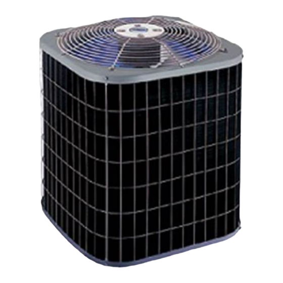
Fig. 1—Model 38CKX
Pg 1
4-01
Replaces: 38CKX-C1SI
A97005
Advertisement
Table of Contents

Subscribe to Our Youtube Channel
Related Manuals for Carrier 38CKX


Summary of Contents for Carrier 38CKX
- Page 1 Consult local These are the Installation and Start-Up Instructions for the codes governing rooftop applications. 38CKX—50 Hz Air Conditioning Unit. Step 3—Replace Indoor AccuRaterT Piston, if Required INSTALLATION Check indoor coil piston to see if it matches the required piston Step 1—Check Equipment and Job Site...
- Page 2 AIR IN DISCHARGE NOTES: 1. Allow 30 in. (762 mm) clearance to service end of unit, 48 in. (1219 mm) above unit, 6 in. (152 mm) on one side, 12 in. (305 mm) on remaining side, and 24 in. (610 mm) between units for proper airflow. AIR IN AIR IN 2.
- Page 3 Table 1—Refrigerant Connections and Recommended Liquid and Vapor Tube Diameters LIQUID VAPOR UNITSIZE Connection Dia Tube Dia Connection Dia Tube Dia 9.53 9.53 15.88 15.88 9.53 9.53 19.05 19.05 9.53 9.53 22.23 22.23 9.53 9.53 22.23 1-1/8 28.58 NOTES: 1. Tube diameters are for lengths up to 50 ft (15.24m). For tube sets over 50 ft (15.24m), consult Long-Line Application Guideline. 2.
- Page 4 NOTE: Avoid contact between tubing and structure. OUTDOOR WALL INDOOR WALL To prevent personal injury wear safety glasses, protective clothing, and gloves when handling refrigerant and observe CAULK the following: LIQUID TUBE • Back seating service valves are not equipped with Schrader valves.
- Page 5 operation and periodic maintenance requirements outlined in manual. Frequency of maintenance may vary depending on geo- graphic areas, such as coastal applications which require more frequent maintenance. A00010 → Fig. 5—Phase Monitor Control CARE AND MAINTENANCE For continued high performance and to minimize possible equip- ment failure, periodic maintenance must be performed on this equipment.
- Page 6 THERMOSTAT MOTOR POWER SUPPLY TRANS COND COOLING ONLY LEGEND: M - INDOOR FAN MOTOR TRANS - TRANSFORMER IFR - INDOOR FAN RELAY A97019 FB4ASX FB4ASX THERMOSTAT FAN COIL THERMOSTAT FAN COIL AIR COND AIR COND COOLING ONLY ONE-STAGE COOLING / ELECTRIC HEAT A97050 A97051 Fig.
- Page 8 Copyright 2001 CARRIER Corp. • 7310 W. Morris St. • Indianapolis, IN 46231 38ckxc2si Manufacturer reserves the right to discontinue, or change at any time, specifications or designs without notice and without incurring obligations. Book 1 4 PC 101 Catalog No. 003-857 Printed in U.S.A.
Need help?
Do you have a question about the 38CKX and is the answer not in the manual?
Questions and answers