Advertisement
Quick Links
Visit www.carrier.com
Installation and Start-Up Instructions
NOTE: Read the entire instruction manual before starting the
installation.
SAFETY CONSIDERATIONS
Improper installation, adjustment, alteration, service, maintenance,
or use can cause explosion, fire, electrical shock, or other
conditions which may cause death, personal injury, or property
damage. Consult a qualified installer, service agency, or your
distributor or branch for information or assistance. The qualified
installer or agency must use factory-authorized kits or accessories
when modifying this product. Refer to the individual instructions
packaged with the kits or accessories when installing.
Follow all safety codes. Wear safety glasses, protective clothing,
and work gloves. Use quenching cloth for brazing operations.
Have fire extinguisher available. Read these instructions thor-
oughly and follow all warnings or cautions included in literature
and attached to the unit. Consult local building codes and National
Electrical Code (NEC) for special requirements.
Recognize safety information. This is the safety-alert symbol
When you see this symbol on the unit and in instructions or
manuals, be alert to the potential for personal injury.
Understand the signal words DANGER, WARNING, and CAU-
TION. These words are used with the safety-alert symbol. DAN-
GER identifies the most serious hazards which will result in severe
personal injury or death. WARNING signifies hazards which
could result in personal injury or death. CAUTION is used to
identify unsafe practices which would result in minor personal
injury or product and property damage.
Before installing, modifying, or servicing system, main elec-
trical disconnect switch must be in the OFF position. There
may be more than 1 disconnect switch. Lock out and tag
switch with a suitable warning label. Electrical shock can
cause personal injury or death.
INSTALLATION RECOMMENDATIONS
NOTE: In some cases noise in the living area has been traced to
gas pulsations from improper installation of equipment.
1. Locate unit away from windows.
2. Ensure that vapor and liquid tube diameters are appropriate to
capacity of unit. (See Model Specific Instructions for proper
tube sizing.)
3. Run refrigerant tubes as directly as possible by avoiding
unnecessary turns and bends.
4. Leave some slack between structure and unit to absorb
vibration.
5. When passing refrigerant tubes through the wall, seal opening
with RTV or other pliable silicon-based caulk. (See Fig. 2.)
6. Avoid direct tubing contact with water pipes, ductwork, floor
joists, wall studs, floors, and walls.
Manufacturer reserves the right to discontinue, or change at any time, specifications or designs without notice and without incurring obligations.
Book 1 4
PC 101
Catalog No. 533-840
Tab 3a 2a
38CKC(Q), 38CMC, 38BRC
Split-System Air Conditioner
.
7. Do not suspend refrigerant tubing from joists and studs with a
rigid wire or strap which comes in direct contact with the
tubing. (See Fig. 2.)
8. Ensure that tubing insulation is pliable and completely sur-
rounds vapor tube.
9. When necessary, use hanger straps which are 1 in. wide and
conform to shape of tubing insulation. (See Fig. 2.)
10. Isolate hanger straps from insulation by using metal sleeves
bent to conform to shape of insulation.
When outdoor unit is connected to factory-approved indoor unit,
outdoor unit contains system refrigerant charge for operation with
factory-approved indoor unit of the same size when connected by
15 ft of field-supplied tubing. For proper unit operation, check
refrigerant charge using charging information located on control
box cover.
Step 1—Check Equipment and Jobsite
INSPECT EQUIPMENT — If shipment is damaged or incom-
plete, file claim with shipping company prior to installation.
Locate unit rating plate on unit service panel. It contains informa-
tion needed to properly install unit. Check rating plate to be sure
unit matches job specifications.
Step 2—Install on a Solid, Level Mounting Pad
If conditions or local codes require the unit be attached to pad, use
tiedown bolts to fasten through knockouts provided in unit base
pan. Refer to Fig. 3 for pad dimensions and dimensions needed to
mount unit to pad.
Printed in U.S.A.
Form 38BRC-1SI
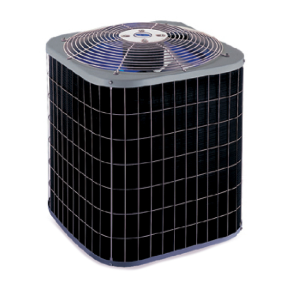
Fig. 1—Split-System Air Conditioner
INSTALLATION
Pg 1
A97005
2-97
Replaces: New
Advertisement

Related Manuals for Carrier 38CKC(Q)


Summary of Contents for Carrier 38CKC(Q)
- Page 1 Visit www.carrier.com Installation and Start-Up Instructions NOTE: Read the entire instruction manual before starting the installation. SAFETY CONSIDERATIONS Improper installation, adjustment, alteration, service, maintenance, or use can cause explosion, fire, electrical shock, or other conditions which may cause death, personal injury, or property damage.
- Page 2 The piston shipped with outdoor unit is correct for any approved indoor coil combination. LIQUID TUBE VAPOR TUBE JOIST INSULATION VAPOR TUBE UNIT SIZE 38CKC(Q)018, 024 38CKC(Q)030-042 LIQUID TUBE 38CMC018-030 38BRC024-060 38CKC(Q)048, 060 38CMC036-060 A94028 Step 6—Make Tubing Connections Relieve pressure and recover all refrigerant before system repair or final unit disposal to avoid personal injury or death.
- Page 3 AIR DISCHARGE FIELD POWER SUPPLY CONN AND 1 KNOCKOUT FIELD CONTROL SUPPLY CONN SUCTION LINE CONN LIQUID LINE CONN LIQUID TUBE UNIT SIZE Conn Dia Tube Dia Conn Dia 018, 024 030, 036 042, 048 NOTE: Tube diameters are for lengths up to 50 ft. For tubing lengths greater than 50 ft, consult your local distributor.
- Page 4 MARK ON LOCK NUT AND TUBE Fig. 7—Proper Marking of Valve Assembly (38CKQ) ELECTRICAL JUNCTION ELECTRICAL COIL VALVE STRAIGHT NOTE: System flow direction must match arrow on bottom of body. Fig. 8—Solenoid Valve Installation Wiring must comply with local codes and NEC requirements, if a field-supplied control power source is needed when adding solenoid.
-
Page 5: Sequence Of Operation
NOTE: Use of available 24-v accessories may exceed the mini- mum 40-va power requirement. Determine total transformer load- ing and increase the transformer capacity or split the load with an accessory transformer as required. Step 9—Compressor Crankcase Heater When equipped with a crankcase heater, furnish power to heater a minimum of 24 hr before starting unit. - Page 6 CORPORATE NON-PROGRAMMABLE THERMOSTAT SINGLE STAGE MODEL AC FURNACE 24 VAC HOT 24 VAC COM W/W1 HEAT STAGE 1 W/W1 Y/Y2 COOL STAGE 1 Y/Y2 INDOOR FAN CORPORATE PROGRAMMABLE THERMOSTAT SINGLE STAGE MODEL AC CONDITIONER FURNACE 24 VAC HOT INDOOR FAN HEAT STAGE 1 W/W1 W/W1...
- Page 7 CORPORATE NON-PROGRAMMABLE THERMOSTAT FK4B MODEL AC FAN COIL CONDITIONER 24 VAC HOT 24 VAC COM HEAT STAGE 1 W/W1 COOL STAGE 1 Y/Y2 Y/Y2 INDOOR FAN NON-CORPORATE NON-PROGRAMMABLE THERMOSTAT MODEL AC 24 VAC HOT HEAT STAGE 1 COOL STAGE 1 INDOOR FAN Fig.
- Page 8 INSTALLATION INSTRUCTIONS. Fig 10—Typical 24-v Circuit Connections (Continued) Copyright 1997 CARRIER Corp. • 7310 W. Morris St. • Indianapolis, IN 46231 Manufacturer reserves the right to discontinue, or change at any time, specifications or designs without notice and without incurring obligations.
Need help?
Do you have a question about the 38CKC(Q) and is the answer not in the manual?
Questions and answers