Table of Contents
Advertisement
Quick Links
Advertisement
Table of Contents

Related Manuals for INOXPA VEEVALV


Summary of Contents for INOXPA VEEVALV
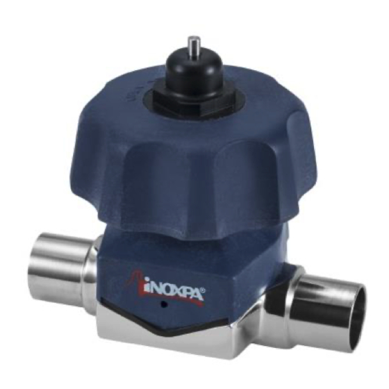
- Page 1 INSTALLATION, SERVICE AND MAINTENANCE INSTRUCTIONS VEEVALV ‘09 INOXPA, S.A. c/Telers, 54 Aptdo. 174 E-17820 Banyoles Girona (Spain) Tel. : (34) 972 - 57 52 00 Fax. : (34) 972 - 57 55 02 Email: inoxpa@inoxpa.com www.inoxpa.com Original Manual 10.300.30.02EN (C) 2021/12...
-
Page 4: Safety
The information published in the instruction manual is based on updated information. INOXPA reserves the right to modify this instruction manual without prior notice. 1.2. START-UP INSTRUCTIONS. This instruction manual contains vital and useful information to correctly install and maintain your valve. -
Page 5: Guarantee
The use of other parts will exempt the manufacturer from any liability. The service terms can only be changed with prior written authorization from INOXPA. Please do not hesitate to contact us in case of doubts or more complete explanations are required on specific data (adjustments, assembly, disassembly, etc.). -
Page 6: Table Of Contents
2. Table of Contents Safety 1.1. Instruction manual......................3 1.2. Start-up instructions....................... 3 1.3. Safety........................... 3 1.4. General safety instructions ....................3 1.5. Guarantee........................4 Table of Contents Receipt and Installation 3.1. Checking the shipment ....................6 3.2. -
Page 7: Receipt And Installation
Nº FABRICACION: MODELO: MANUFACTURING NR.: MODEL: 3.2. DELIVERY AND UNPACKING INOXPA will not be responsible for the inappropriate unpacking of the valve and its components. 3.2.1. Delivery: Check that all the parts indicated on the delivery note are correct •... -
Page 8: Identification
3.4. IDENTIFICATION 0 - 00 52 025 SURFACE FINISH Exterior / Interior Ra >0.5 (standard) - MIRROR / MIRROR Ra >0.8 / Ra >0.5 - SATIN / MIRROR NOMINAL DIAMETER 003 - DN 1/8” 032 - DN 32 (DN 1 1/4'') 004 - DN 4 038 - DN 1 ½”... -
Page 9: Assembly
3.6. ASSEMBLY Install the valve in process pipework according to good trade practice. Once the location of the valve has been established, the pipes can be connected by either welding to the body of the valve or by means of hygienic unions. In the latter case ensure that seals are fitted and the joints fully tightened. Before welding the bodies to the pipework, disassemble the valve to prevent damage to the diaphragm. -
Page 10: Welding
Connect and check the air connections as required. Single Acting Spring Return or Double Acting. • INOXPA valves are supplied with Ø6 tube connections and a silencer in Single Acting actuators. • Bear in mind the quality of the compressed air in accordance with the specifications described in chapter 8 Technical Specifications. -
Page 11: Start-Up
Do not modify the operating parameters for which the valve has been designed without written prior authorization from INOXPA. Visually check that the sealed area has no leaks. The valves are provided with a leak detector. -
Page 12: Operating Problems: Causes And Solutions
5. Operating Problems: Causes and Solutions PROBLEM CAUSE/EFFECT SOLUTION AIR LEAKING • Replace the O-ring. THROUGH LEAK The O-ring on the shaft is worn or damaged. DETECTOR • Plastic actuator: replace the O-ring AIR LEAKING The O-ring of the piston is worn or damaged. •... -
Page 13: Maintenance
6. Maintenance 6.1. GENERAL This valve, just like any other machine, requires maintenance. The instructions contained in this manual cover the identification and replacement of spare parts. The instructions have been prepared for maintenance personnel and for those responsible for the supply of spare parts. Technical Specifications. -
Page 14: Cleaning
6.2.3. Spare parts To request spare parts, it is necessary to indicate the type of valve, the position and the description of the part which Technical Specifications can be found in the chapter 8. 6.3. CLEANING The use of aggressive cleaning products such as caustic soda and nitric acid may cause burns to the skin. -
Page 15: Assembly And Disassembly
7. Assembly and Disassembly Proceed with caution. There is danger of personal injury. Never disassemble the valve screws without reading the instructions thoroughly. Assembly and disassembly of the valves / actuator must only be carried out by qualified staff. When assembling the diaphragm it is very important to comply with the sequence of steps, as otherwise, the diaphragm may be damaged. -
Page 16: Procedure For Adjusting To Closure Of The Manual Valve
Proceed with caution. There is danger of personal injury. Never disassemble the valve screws without reading the instructions thoroughly. Assembly and disassembly of the valves / actuator must only be carried out by qualified staff. When assembling the diaphragm it is very important to comply with the sequence of steps, as otherwise, the diaphragm may be damaged. -
Page 17: Disassembly / Assembly Of The Pneumatically Actuated Valve
Proceed with caution. There is danger of personal injury. Never disassemble the valve screws without reading the instructions thoroughly. Assembly and disassembly of the valves / actuator must only be carried out by qualified staff. When assembling the diaphragm it is very important to comply with the sequence of steps, as otherwise, the diaphragm may be damaged. -
Page 18: Technical Specifications
58 PSI 58 PSI 58 PSI Working pressures determined from the hydrostatic pressure applied on one side of the closed valve. For working pressures applied on both sides, consult INOXPA. (may vary according to model; consult INOXPA) Minimum working pressure Vacuum... - Page 19 VALVE MATERIALS Parts in contact with the product AISI 316L Other steel parts AISI 304 Plastic parts PP+ 30% GF / PC / POM Gaskets in contact with the fluid EPDM (Standard) - VMQ – FPM – EPDM/PTFE separate In contact with the fluid: Ra 0.5 μm (Standard) Surface finish in steel parts External surfaces: mirror finish (Standard), satin finish, shot-blasted.
-
Page 20: Manually Actuated Valve Dimensions
8.1. MANUALLY ACTUATED VALVE DIMENSIONS Weld OD Clamp SMS male Size 1/4" 3/8" Nº1 1,65 25,4 1/2" 12,7 5/8" 15,9 12,6 3/4" 15,8 25,4 Nº2 1,65 1" 25,4 22,1 50,5 22,5 Nº3 1 1/2" 38,1 1,65 34,8 50,5 35,5 Nº4 2"... -
Page 21: Stainless-Steel Pneumatically Actuated Valve Dimensions
8.2. STAINLESS-STEEL PNEUMATICALLY ACTUATED VALVE DIMENSIONS Weld OD Clamp SMS Male Size 1/4" 3/8" Nº1 1,65 25,4 1/2" 12,7 5/8" 15,9 12,6 3/4" 15,8 25,4 Nº2 1,65 1" 25,4 22,1 50,5 22,5 Nº3 1 1/2" 38,1 1,65 34,8 50,5 35,5 Nº4 2"... -
Page 22: Section And Parts List
8.3. SECTION AND PARTS LIST 8.3.1. Section and parts list for MANUALLY ACTUATED VALVE Nº1, Nº2 & Nº3 POSICIÓN DESIGNACIÓN MATERIAL CANTIDAD Body CF 3M Handle CF 8 / PP+30GF Diaphragm Cover Shaft AISI 304 Bonnet CF 3M / PP+30GF Bushing Brass O-ring... - Page 23 8.3.2. Section and parts list for MANUALLY ACTUATED VALVE Nº4 (Without stroke limiter) POSICIÓN DESIGNACIÓN MATERIAL CANTIDAD Body CF 3M Handle CF 8 Diaphragm Cover Shaft AISI 304 Bonnet CF 3M Bushing Brass O-ring O-ring O-ring DIN 912 Allen screw WASHER DIN 127 Bottom washer PTFE+GF...
- Page 24 8.3.3. Section and parts list for STAINLESS-STEEL PNEUMATICALLY ACTUATED VALVE POSICIÓN DESIGNACIÓN MATERIAL CANTIDAD Casing CF 3M Diaphragm Indicator Glass Actuator AISI 304 Straight connector R 1/8” Silencer R 1/8” O-ring DIN 912 Allen screw WASHER DIN 127 2021/12 8.Technical Specifications...
- Page 25 NOTES...
- Page 26 NOTES...
- Page 27 NOTES...
- Page 28 Tel. +351 256472722 comercial.pt@inoxpa.com In addition to our branch offices, INOXPA operates with an independent distributor network which encompasses a total of more than 50 countries throughout the world. For more information consult our web page: www.inoxpa.com This information is a guideline only. We reserve the right to modify any material or characteristic without prior notice.
Need help?
Do you have a question about the VEEVALV and is the answer not in the manual?
Questions and answers