Table of Contents
Advertisement
Advertisement
Table of Contents

Related Manuals for Buchi V-300


Summary of Contents for Buchi V-300
- Page 1 Vacuum Pump V-300 Operation Manual...
- Page 2 CH-9230 Flawil 1 E-Mail: quality@buchi.com BUCHI reserves the right to make changes to the manual as deemed necessary in the light of experience, especially with respect to structure, illustrations and technical details. This manual is copyrighted. Information from it may neither be reproduced, distributed, or used for competitive purposes, nor made available to third parties.
-
Page 3: Table Of Contents
3.3.4 Internal view...................... 16 3.3.5 Type plate ......................... 17 3.3.6 ATEX supplementary plate .................. 17 Specifications supplied ...................... 18 Technical data ........................ 19 3.5.1 Vacuum Pump ...................... 19 3.5.2 Ambient conditions .................... 19 3.5.3 Materials ........................ 19 Transport and storage ...................... 21 Transport .......................... 21 Storage .......................... 21 Operation Manual Vacuum Pump V-300... - Page 4 Fitting a VacuBox ........................ 33 5.11 Connecting the vacuum pump to the power supply............. 35 5.12 Connecting communication cables to the V-300 .............. 36 5.13 Assembling the BUCHI distillation system................ 37 5.13.1 Overview: Setting up communication connections (COM) ........ 38 5.13.2 Overview: setting up coolant tubing connections............ 39 5.13.3 Overview: setting up vacuum tubing connections............. 40...
- Page 5 Appendix .......................... 63 10.1 Solvent table........................ 63 10.2 Spare parts and accessories .................... 64 10.2.1 Accessories ...................... 64 10.2.2 Wearing parts ...................... 67 10.2.3 Spare parts ....................... 69 10.3 Document: 11594022 ATEX.................... 71 10.4 Health and safety approval.................... 72 10.5 Health and safety......................... 73 Operation Manual Vacuum Pump V-300...
-
Page 6: About This Document
They are an integral part of the product and contain important information that is necessary for safe operation and maintenance. These operating instructions apply to all variants of the [Vacuum Pump V-300] and are intended primarily for laboratory staff. -
Page 7: Mandatory Directive Symbols
These operating instructions were originally produced in German and have been translated into several other languages. The translations are available on the enclosed CD or can be obtained as a PDF file via http://www.buchi.com. Trademarks Product names and registered or unregistered trademarks that are used in this instruction manual are used only for identification and remain the property of the owner in each case. -
Page 8: Safety
Safety Intended use The [Vacuum Pump V-300] has been designed and built as an item of laboratory equipment. Its intended use is the evacuation of laboratory apparatus. This is done by means of a PTFE-diaphragm pump – with or without regulation by a vacuum controller. -
Page 9: Residual Risks
— Safety-related incidents that occur while using the device should be reported to the manufacturer (quality@buchi.com). BUCHI service technicians Service technicians authorized by BUCHI have attended special training courses and are authorized by BÜCHI Labortechnik AG to carry out special servicing and repair measures. -
Page 10: Personal Protective Equipment
Technical modifications to the device or accessories should only be carried out with the prior written approval of BÜCHI Labortechnik AG and only by authorized BUCHI technicians. BUCHI accepts no liability whatsoever for damage arising as a result of unauthorized modifications. 10/76... -
Page 11: Product Description
5 mbar (± 2 mbar). It can be operated either as a standalone device or combined with optional accessories (see Specifications supplied). Once switched on, the Vacuum Pump V-300 runs in continuous mode unless it is connected to the Interface I-300/I-300 Pro unit. In unregulated continuous mode, the pump runs at a maximum speed of 1500 rpm and generates a terminal vacuum of 5 mbar (± 2 mbar). -
Page 12: Configuration
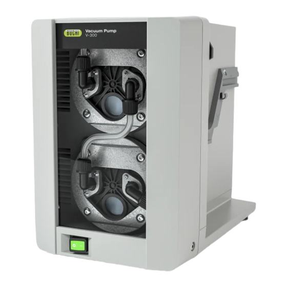
— See Chapter 3.5 "Technical data", page 19 — See Chapter 2.2 "Use other than that intended", page 8 — See Chapter 7 "Cleaning and servicing", page 45 Configuration 3.3.1 Front view Fig. 1: Design of V-300 Carrying handle Casing front Inspection window On/Off master switch 12/76 Operation Manual Vacuum Pump V-300... -
Page 13: Rear View
Büchi Labortechnik AG Product description | 3 3.3.2 Rear view Fig. 2: Rear view of V-300 Pump outlet Ventilation slots Pump intake (vacuum) Type plate/ATEX supplementary plate Mounting rail for accessory compo- Connection panel for communication nents cables (see Chapter 5.12 "Connecting communication cables to the V-300",... -
Page 14: Connections
— Digital ON/OFF control of the pump via legacy devices (V-850 / V-855, V-800 / V-805) or via the VacuBox. — Operation of two Rotavapor systems with only one Vacuum Pump V-300, see Operating the Vacuum Pump V-300 with 2 Rotavapor systems. - Page 15 Digital input ON/OFF Connection for fill level sensor (LEVEL) A fill-level sensor can be connected to the Vacuum Pump V-300 as an option. The fill- level sensor measures the fill level of the receiving flask if a secondary condenser or a secondary cold trap is connected to the V-300.
-
Page 16: Internal View
Büchi Labortechnik AG 3 | Product description 3.3.4 Internal view Fig. 5: Internal view of V-300 showing pump heads Pump head fixing ring Connection (pump intake) GL14 union nut Pump-head connecting tube Connection (pump outlet) 16/76 Operation Manual Vacuum Pump V-300... -
Page 17: Type Plate
ATEX mark ATEX mark Note: Note: Only suitable for the area in contact For more information refer to the with the fluid inside the vacuum document 1159022 ATEX pump. See Chapter 10.3 "Document: 11594022 ATEX", page 71 Operation Manual Vacuum Pump V-300 17/76... -
Page 18: Specifications Supplied
Vacuum tubing (2 m) Mains cables Silencer Tubing connections (set) Interface I-300 Woulff bottle Secondary cold trap Secondary condenser Communication cables Diaphragm grips Torx key Tx10 Torx key Tx25 The components marked * are optional. 18/76 Operation Manual Vacuum Pump V-300... -
Page 19: Technical Data
Ambient temperature 5 - 40 °C Maximum relative humidity 80 % for temperatures up to 31 °C decreasing linearly to 50 % at 40 °C The [Vacuum Pump V-300] may only be used in indoor areas. 3.5.3 Materials Component Material... - Page 20 Büchi Labortechnik AG 3 | Product description Component Material Drive unit body Aluminum Casing Diaphragms EPDM/PTFE Valve plate PEEK Valve body PEEK Pump-head connecting tube Vacuum tubing Norprene Non-return valve O-rings 20/76 Operation Manual Vacuum Pump V-300...
-
Page 21: Transport And Storage
Make sure that the ambient conditions are complied with (see Chapter 3.5 "Technical data", page 19). Wherever possible, store the device in its original packaging. After storage, check the device, all glass components, seals and tubing for damage and replace if necessary. Operation Manual Vacuum Pump V-300 21/76... -
Page 22: Installation
Connect a Woulff bottle upstream of the pump intake. Operate the pump inside a fume hood. CAUTION Health risks when handling corrosive substances. When working with strong acids or caustic solutions, always wear personal protective equipment (safety goggles, protective clothing, protective gloves). 22/76 Operation Manual Vacuum Pump V-300... -
Page 23: Installation Site
— Sufficient clearance on all sides of the device (approx. 10 cm) in order to ensure air circulation — Clear air outlet at the rear (ventilation slots must be kept clear) The [V-300] is intended for use in laboratory environments. See Chapter 3.5.2 "Ambient conditions", page 19. Operation Manual Vacuum Pump V-300... -
Page 24: Securing Against Earthquakes
Büchi Labortechnik AG 5 | Installation Securing against earthquakes The Vacuum Pump V-300 has an earthquake fixing to protect the device against falling. Fig. 8: Lashing eye for securing against falling during earthquakes Lashing eye Thread a strong cord or a wire through the lashing eye (1). -
Page 25: Connecting Laboratory Equipment
Pump intake (vacuum) The laboratory apparatus to be evacuated is connected to the optional Woulff bottle. The Woulff bottle is connected to the pump intake (2) of the V-300 using a GL14 connection. Connect a Woulff bottle upstream of the pump intake (see Chapter 5.6 "Connecting a Woulff bottle", page 28). -
Page 26: Connecting The Silencer
Büchi Labortechnik AG 5 | Installation Connecting the silencer The silencer can be connected directly to the V-300 or to the outlet of a secondary condenser. 5.5.1 Connecting silencer directly to V-300 Fig. 10: Silencer on pump outlet of V-300 GL14 cap nut on silencer inlet... -
Page 27: Connecting The Silencer To The Outlet Of The Secondary Condenser
Silencer GL14 cap nut Precondition: R A secondary condenser (1) is mounted on the pump outlet of the V-300 and connected up, see Connecting a secondary condenser. Fit the silencer (3) on the secondary condenser outlet. Slide the GL14 cap nut forward and tube seal on the silencer inlet (2) and screw it onto the GL14 thread of the secondary condenser outlet. -
Page 28: Connecting A Woulff Bottle
Outlet for VacuBox connection Woulff bottle glass component Woulff bottle holder The Woulff bottle is fixed to a mounting rail on the V-300 and is connected to the pump intake. Fit the holder (8) around the neck of the Woulff bottle. -
Page 29: Connecting The Vacubox Via A Woulff Bottle
Fit a connecting tube to the outlet of the Woulff bottle (3) and the vacuum connection of the VacuBox (1). If necessary, fit a connecting tube to the inlet of the Woulff bottle (4) and the vacuum connection of the cooling condenser (5). Operation Manual Vacuum Pump V-300 29/76... - Page 30 V-300", page 36. NOTE In a BUCHI distillation system, the VacuBox and Woulff bottle can alternatively be mounted on the Rotavapor® instead of on the vacuum pump. What is important is that the VacuBox and Woulff bottle are as close as possible to each other (on the same device) as otherwise there is a vacuum control lag.
-
Page 31: Connecting A Secondary Condenser
Fit receiving flask (11) onto the bottom outlet of the secondary condenser and fix with the aid of a catchpot clip (10). Option: From the outlet of the secondary condenser (6), feed another connecting tube directly into a fume hood. Operation Manual Vacuum Pump V-300 31/76... -
Page 32: Connecting A Secondary Cold Trap
Fit receiving flask (9) onto the bottom outlet of the secondary cold trap and fix with the aid of a catchpot clip (8). From the outlet (6) of the secondary cold trap, feed another connecting tube directly into a fume hood. 32/76 Operation Manual Vacuum Pump V-300... -
Page 33: Fitting An Interface I-300
(5) inserted from the back. 5.10 Fitting a VacuBox Fitting and connection of a VacuBox to the V-300 are necessary if the pump is to be controlled via an Interface I-300/I-300 Pro. For details, see Chapter 5.13 "Assembling the BUCHI distillation system", page 37. - Page 34 Press fixing brackets (1) into the holes in the top and bottom of the VacuBox. The wider of the two fixing brackets has to be fitted at the bottom. Position the VacuBox (3) on the rear of the V-300 on the left inner face of the recess.
-
Page 35: Connecting The Vacuum Pump To The Power Supply
Installation | 5 5.11 Connecting the vacuum pump to the power supply Fig. 17: Electrical connections on the V-300 Power supply connection Plug the power cord into the power supply socket (1) on the pump and then into a mains power socket. Make sure that the available power supply matches the rating indicated on the type plate. -
Page 36: Connecting Communication Cables To The V-300
Fill level sensor connection (LEVEL) Plug the communication cable for connection to other BUCHI laboratory equipment into one of the two standard BUCHI communication ports (3). Plug the communication cable into the green communication port on the other item of laboratory equipment. For details of connecting the equipment via the communication ports see Chapter 5.13.1 "Overview: Setting up communication... -
Page 37: Assembling The Buchi Distillation System
The Interface I-300/I-300 Pro together with the VacuBox can be used to control and monitor the vacuum. It can control the Rotavapor, the Vacuum Pump V-300/V-600 and the Recirculating Chiller F-3xx. The Vacuum Pump V-300/V-600 is a diaphragm pump designed for evacuating laboratory apparatus. -
Page 38: Overview: Setting Up Communication Connections (Com)
As well as the interface unit, a VacuBox also has to be connected. Below is an example of the connections between the laboratory apparatus. Vacu Dongle StatusLight Vacuum Pump Recirculating Destilation unit Chiller Interface Fig. 19: Schematic diagram of communication connections between the BUCHI laboratory equipment (example) 38/76 Operation Manual Vacuum Pump V-300... -
Page 39: 5.13.2 Overview: Setting Up Coolant Tubing Connections
Connect a tube between the outlet of the condenser on the Rotavapor R-300 (4) and the inlet of the secondary condenser on the Vacuum Pump V-300/V-600 (5). Connect a tube between the outlet of the secondary condenser on the Vacuum Pump V-300/V-600 (6) and the inlet of the recirculating chiller (1). -
Page 40: 5.13.3 Overview: Setting Up Vacuum Tubing Connections
The vacuum tubing connections in a typical BUCHI distillation system lead from the Rotavapor R-300 via a Woulff bottle to the Vacuum Pump V-300/V-600. The vacuum is measured by means of the VacuBox, which is also connected to the Woulff bottle. -
Page 41: Operating The Vacuum Pump With 2 Rotavapor Systems
— 2x Interface I-300/I-300 Pro — 2x Valve unit — 2x VacuBox — 1x Y-cable — 2x Standard BUCHI communication cable — 1x Vacuum Pump V-300 — If an R-300 is not used: 2x mains adaptor and lead Operation Manual Vacuum Pump V-300... - Page 42 Connect up each set of 1 Rotavapor R-300, 1 Interface I-300/I-300 Pro and 1 VacuBox via the standard BUCHI communication ports (1). Connect vacuum tubing from each valve unit to one Rotavapor R-300 and one VacuBox. To do so, use the CONTR inlets (B) for the Woulff bottle.
- Page 43 Büchi Labortechnik AG Installation | 5 If a Rotavapor R-300 is not used, connect each VacuBox to the external power supply by means of a mains adaptor (3). Operation Manual Vacuum Pump V-300 43/76...
-
Page 44: Operation
Chapter 3.1 "Description of function", page 11. To start the pump, switch on the master switch on the front of the V-300. Operating V-300 with Interface I-300/I-300 Pro The Vacuum Pump V-300 can also be externally controlled by an Interface I-300/ I-300 Pro. -
Page 45: Cleaning And Servicing
Any servicing and repair work which involves opening up more than the casing front may only be carried out by authorized service technicians. Use only genuine BUCHI consumables and spare parts in order to ensure correct operation of the device and preserve the warranty. -
Page 46: Cleaning The Casing
To clean the casing, only use ethanol or soapy water. 7.1.4 Cleaning glass components On the front of the V-300 there is an inspection window made of glass. That inspection window may mist over or become dirty from vapors. Remove the casing front, see Chapter 7.2.2 "Dismantling and reassembling pump head", page 49. -
Page 47: Cleaning Internal Pump Tubing
If the pump is opened up while it is running there is a risk of dangerous electric shocks. Before carrying out any cleaning or servicing work, always shut down the device and disconnect the power cable. Operation Manual Vacuum Pump V-300 47/76... - Page 48 Risk of pump damage and loss of warranty entitlement. Unauthorized opening up of any casing components apart from the front casing may permanently impair the function of the pump. Only allow authorized BUCHI service technicians to open up the rear part of the pump. WARNING Creation of sparks by foreign particles in the vacuum system.
-
Page 49: Dismantling And Reassembling Pump Head
Cleaning and servicing | 7 7.2.2 Dismantling and reassembling pump head The two pump heads and the pump-head connecting tubes are located behind the front casing (1). Fig. 23: front casing of V-300 front casing Torx key Tx10 (supplied) Fixing screws Fixing screws... - Page 50 Pump-head connecting tube GL14 cap nut Connection for pump outlet The V-300 has three pump-head connecting tubes as follows: — Connecting tube (1) between upper pump head and pump intake connection — Connecting tube (7) between the two pump heads —...
- Page 51 Büchi Labortechnik AG Cleaning and servicing | 7 Remove the two elbow connectors together with the connecting tube (7). Step 2: dismantling pump head Fig. 25: Pump head and diaphragm of V-300 Pump head Torx-head screws Fixing ring Tools required: — Torx key Tx25 Using a Torx key, unscrew the four Torx-head screws (3).
-
Page 52: Replacing The Diaphragm
7.2.3 Replacing the diaphragm Diaphragms must be replaced if they are defective or dirty and previous cleaning has not successfully remedied the problem. Fig. 26: Pump head and diaphragm of V-300 Diaphragm Tools required: — Diaphragm grips (see Spare parts). Precondition: R Pump has been shut down. -
Page 53: Replacing The Non-Return Valve
7.2.4 Replacing the non-return valve On each of the two pump heads of the V-300 there are two non-return valves with O-rings (see Chapter 7.2.6 "Replacing O-rings", page 57). They are inside the elbow connectors. To access the valves, the connecting tubes and elbow connectors first have to be removed from the pump heads. - Page 54 The diaphragm grips supplied have a notch in the front of the right-hand grip. This can be used as an aid to removing the non-return valves from the elbow connectors. Fig. 30: Diaphragm grips with notch in right-hand grip for removing non-return valves 54/76 Operation Manual Vacuum Pump V-300...
-
Page 55: Replacing Connecting Tubes
Cleaning and servicing | 7 7.2.5 Replacing connecting tubes The V-300 has a total of three connecting tubes on the pump heads, see Chapter "Step 1: removing connecting tubes", page 50. Replacing pump-head connecting tube Fig. 31: Pump-head connecting tube in V-300... - Page 56 Büchi Labortechnik AG 7 | Cleaning and servicing Replacing connecting tube to pump intake or pump outlet Fig. 32: Connecting tubes to the V-300 pump heads Connecting tube Fixing screws for elbow connector GL14 union nut Elbow connector Tools required: — Torx key Tx10 Remove the front casing, see Chapter 7.2.2 "Dismantling and reassembling pump...
-
Page 57: Replacing O-Rings
7.2.6 Replacing O-rings The O-rings have to be replaced if the V-300 is no longer functioning at full capacity and no longer achieving the terminal vacuum. In such cases, it makes sense to replace all four O-rings in the elbow connectors on the pump heads (see Chapter 7.2.4 "Replacing the non-return valve", page 53). -
Page 58: Removing Non-Return Valve From Elbow Connector
Slide the connector (4) up to the top of the notch in the diaphragm grips. Press the connector upwards slightly so that the non-return valve twists in the notch and then tilt it down. ð The non-return valve and O-ring come away from the connector. 58/76 Operation Manual Vacuum Pump V-300... -
Page 59: Fitting Gl14 Cap Nut With Tube Seal
Loosely screw the GL14 cap nut together with tube seal onto the device concerned (example shows VacuBox) or the Woulff bottle. Carefully insert the end of the tube (3) into the GL14 cap nut and tube seal. Tighten the GL14 cap nut and tube seal. Operation Manual Vacuum Pump V-300 59/76... -
Page 60: Help With Faults
Check seating of casing front erly closed. and correct if necessary. The cover is fixed by two knurled- head screws. Pump starts then stops Fan is defective. Contact BUCHI Customer again shortly afterwards Service. (in standalone opera- tion). 60/76 Operation Manual Vacuum Pump V-300... -
Page 61: Customer Service
The addresses of the official BUCHI Customer Service offices can be found on the BUCHI website at: www.buchi.com. If you have any questions regarding technical issues or faults, please contact those offices. -
Page 62: Taking Out Of Service And Disposal
Switch off the pump and disconnect it from the mains power supply. Disposal The operator is responsible for proper disposal of the [Vacuum Pump]. When disposing of equipment observe the local regulations and statutory requirements regarding waste disposal. 62/76 Operation Manual Vacuum Pump V-300... -
Page 63: Appendix
0.660 Isopropanol 60.1 0.786 Isopentanol 88.1 0.809 Methylethylketone 72.1 0.805 Methanol 32.0 1227 0.791 Dichlormethane 84.9 1.327 Pentane 72.1 0.626 n-propanol 60.1 0.804 Pentachloroethane 202.3 1.680 1,1,2,2-tetra- 167.9 1.595 chloroethane Tetrachloromethane CCl 153.8 1.594 Operation Manual Vacuum Pump V-300 63/76... -
Page 64: Spare Parts And Accessories
– 10.2 Spare parts and accessories Use only genuine BUCHI consumables and spare parts in order to ensure correct, safe and reliable operation of the system. NOTE Any modifications of spare parts or assemblies are only allowed with the prior written permission of BUCHI. - Page 65 Chiller F-305 / F-308 / F-314. Communication cable. Mini-DIN, Y-piece, 2.0 m 11062255 Meant to be used with 1 Vacuum Pump V-300 and 2 Ro- tavapor® systems with the Interface I-300/I-300 Pro. Con- nection between VacuBox and Vacuum Pump V-300.
- Page 66 Bluetooth® Needed for firmware updates and eSupport. Fastening set. For VacuBox, incl. holder 2 pcs, 11062957 tube Used to fasten VacuBox on the Vacuum Pump V-300 or V-600. Holder set. For V-7xx secondary condenser on 11065095 V-300 / V-600 Used to mount V-7xx secondary condenser on the Vacuum Pump V-300 or V-600.
-
Page 67: 10.2.2 Wearing Parts
Content: Hose barbs, cap nuts, seals. Hose barbs. set. 4 pcs, straight, GL14, FPM seal 040296 Content: Hose barbs, cap nuts, seals. Hose barbs, set. 4 pcs, straight, GL14, silicone 037642 seal Content: Hose barbs, cap nuts, seals Operation Manual Vacuum Pump V-300 67/76... - Page 68 041999 seal EPDM Content: Cap nuts, seals Cap nuts. set. 10 pcs, screw cap with hole, GL14 041956 Membrane, set. 2x, for V-300 / V-600, V-100, 11065776 V-7xx Content: 2 membranes with support rings and 1 membrane clamp. O-ring. For secondary condenser, FKM/FEP, 11057661 Ø28.2/2.6 mm...
-
Page 69: 10.2.3 Spare Parts
Condenses remaining vapors after the vacuum pump outlet. Application temperature: -70 to 40 °C. Used with ice/dry ice. Content: Secondary cold trap condenser and cap nut GL14 (1 pcs). Compatible with V-100, V-7xx, V-300 and V-600 vacuum pumps. Secondary condenser V. Glass condenser 11059902 Condenses remaining vapors after the vacuum pump outlet. - Page 70 6 pcs, for cap nut GL14, EPDM seal Silencer. Attached at the back of the pump. 11062291 Use: Absorb the sound from the vacuum pump. Compatible with Vacuum Pumps V-700, V-710, V-100, V-300 and V-600. Wrench 040469 Torx, TX 25...
-
Page 71: Document: 11594022 Atex
But if such an atmosphere does nevertheless occur, then in all probability it will happen only rarely and for a short period of time. The V-300 and V-600 are suitable for processing fluids in explosive class IIC and fluids with a flashpoint >... -
Page 72: Health And Safety Approval
If the product is contaminated, inform the carrier (in accordance with GGVE/ GGVS/RID/ADR). If the declaration is missing or the procedure described is not followed, the repairs will be delayed. We ask for your understanding and cooperation with regard to these measures. 72/76 Operation Manual Vacuum Pump V-300... -
Page 73: Health And Safety
— we have taken all measures necessary to prevent potential hazards in respect of the products returned. Company name or stamp: Place, date: Name (block letters), position (block letters): Operation Manual Vacuum Pump V-300 73/76... - Page 74 Büchi Labortechnik AG 10 | Appendix Signature: 74/76 Operation Manual Vacuum Pump V-300...
- Page 76 T +971 4 313 2860 T +52 55 9001 5386 F +66 2 862 08 54 F +971 4 313 2861 latinoamerica@buchi.com bacc@buchi.com middleeast@buchi.com www.buchi.com/es-es www.buchi.com/th-th www.buchi.com We are represented by more than 100 distribution partners worldwide. Find your local representative at: www.buchi.com...
Need help?
Do you have a question about the V-300 and is the answer not in the manual?
Questions and answers