Advertisement
Quick Links
Advertisement

Subscribe to Our Youtube Channel
Related Manuals for BDI Corridor 6531


Summary of Contents for BDI Corridor 6531
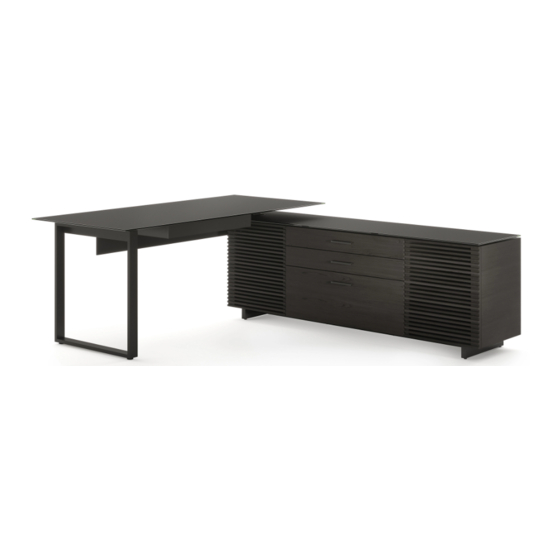
- Page 1 CORRIDOR 6531 ® L-DESK INSTRUCTION MANUAL LET’S GET STARTED. DESIGN MATTHEW WEATHERLY...
- Page 3 Congratulations on the purchase of your Corridor L-Desk 6531 from BDI. Your desk has been designed to provide a lifetime of enjoyment. This manual will provide you with assembly instructions and other helpful information that will ensure that you get the most out of your desk.
- Page 4 Unpack and identify the parts listed below. Note that some components are shipped inside the cabinet. The assembly workspace should be a non-marring surface such as carpet. For missing hardware pieces, please contact BDI Customer Service at customerservice@bdiusa.com. Do not use power tools for assembly of this product.
- Page 5 HARDWARE AND COMPONENTS PART # PART # PART # M6.3 x 8mm DESCRIPTION DESCRIPTION DESCRIPTION BDI Kleet Wood Screw Wood Screw QUANTITY QUANTITY QUANTITY PART # PART # PART # DESCRIPTION M6 x 12mm Screw DESCRIPTION Shelf Pins DESCRIPTION File Bar Clip...
- Page 6 HARDWARE AND COMPONENTS HARDWARE AND COMPONENTS PART # PART # DESCRIPTION DESCRIPTION Cabinet Desktop QUANTITY QUANTITY PART # PART # DESCRIPTION DESCRIPTION Keyboard Drawer Adjustable Shelf QUANTITY QUANTITY PART # PART # DESCRIPTION DESCRIPTION Leg Plate Cabinet Leg QUANTITY QUANTITY 6 | BDIUSA.COM CORRIDOR L-DESK 6531...
- Page 7 HARDWARE AND COMPONENTS PART # PART # PART # Connection DESCRIPTION DESCRIPTION DESCRIPTION Base Rail “T” Bracket Socket QUANTITY QUANTITY QUANTITY PART # DESCRIPTION Desk Rail QUANTITY PART # PART # DESCRIPTION Desk Leg DESCRIPTION Cabinet Glass QUANTITY QUANTITY PART # PART # DESCRIPTION DESCRIPTION...
- Page 8 ASSEMBLY STEP 1. ASSEMBLE CABINET LEGS Attach the (C5) Leg Plates to the (C6) Legs PART/DESCRIPTION using 4 (H1) Screws per leg going through the countersunk holes and into the leg. Tighten with (T1) Hex Wrench. T1-HEX WRENCH H1-SCREW 8 | BDIUSA.COM CORRIDOR L-DESK 6531...
- Page 9 2 PERSON TASK STEP 2. ATTACH BASE RAIL & LEGS TO CABINET ASSEMBLY With help from another person carefully lay the PART/DESCRIPTION (C1) Cabinet onto its back. Attach (C7) Base Rail to the bottom of the cabinet using 4 (H2) Screws. Tighten with (T1) Hex Wrench.
- Page 10 2 PERSON TASK ASSEMBLY STEP 3. ATTACH GLASS BUMPERS With help from another person, carefully PART/DESCRIPTION position the (C1) Cabinet onto its base. Remove adhesive from 6 (H4) Glass Bumpers and attach to the top of the (C1) Cabinet in the H4-GLASS BUMPER positions shown.
- Page 11 STEP 4. ATTACH CONNECTION SOCKET ASSEMBLY Open the door on the side you wish to secure the PART/DESCRIPTION desk. Attach the (C8) Connection Socket to the side wall of the (C1) Cabinet using 5 (H3) Screws. Partially tighten with (T1) Hex Wrench. T1-HEX WRENCH Add 2 more (H3) Screws attaching (C8) Connection Socket into the top panel.
- Page 12 ASSEMBLY STEP 5. ATTACH DRAWER PULLS Attach 3 (H6) Drawer Pulls with 2 (H5) Screws PART/DESCRIPTION each. Tighten with a (T2) Phillips Screwdriver. T2-PHILLIPS SCREWDRIVER H5-SCREW H6-DRAWER PULL 12 | BDIUSA.COM CORRIDOR L-DESK 6531...
- Page 13 STEP 6. ATTACH “T” BRACKET ASSEMBLY Insert the (C9) “T” Bracket into the (C8) Connection PART/DESCRIPTION Socket. Ensure the arrow on the top of the Bracket is pointing towards the desk. Fasten the (C9) “T” Bracket to the (C8) Connection Socket T1-HEX WRENCH using 2 (H3) Screws.
- Page 14 2 PERSON TASK ASSEMBLY STEP 7. ATTACH DESK LEG TO DESKTOP ASSEMBLY With the help of another person, carefully place the PART/DESCRIPTION (C2) Desktop Assembly upside down on a soft surface. Attach (C10) Desk Leg to (C2) Desktop Assembly using 3 (H7) Screws. Partially tighten with T1-HEX WRENCH (T1) Hex Wrench.
- Page 15 STEP 8. ATTACH DESK RAIL ASSEMBLY Attach (C11) Desk Rail to the underside of the PART/DESCRIPTION (C2) Desktop Assembly using 4 (H2) Screws. Ensure the flat plate on the end is facing the (C10) Desk Leg. Partially tighten with (T1) Hex T1-HEX WRENCH Wrench.
- Page 16 ASSEMBLY STEP 9. INSTALL KEYBOARD DRAWER Place the (C3) Keyboard Drawer on the PART/DESCRIPTION (C2) Desktop panel’s appropriate position relative to where the desk will be mounted to the T2-PHILLIPS cabinet. The (C3) Keyboard Drawer should be SCREWDRIVER facing the middle of the cabinet when the desk is mounted.
- Page 17 STEP 10. INSTALL KLEETS ASSEMBLY Install (H10) Kleets to the (C2) Desktop panel on PART/DESCRIPTION the opposite side of the drawer using pre-drilled pilot holes in the desk’s underside. Fasten using T2-PHILLIPS 6 (H11) Wood Screws using the (T2) Phillips SCREWDRIVER Screwdriver.
- Page 18 2 PERSON TASK ASSEMBLY STEP 11. ATTACH DESKTOP TO CABINET With the help of another person, carefully flip the desktop over and rest it on the (C9) “T” Bracket. The (C9) “T” Bracket should rest in grooves in the underside of the desktop. Using 4 (H3) Screws, fasten the desktop to PART/DESCRIPTION the (C9) “T”...
- Page 19 2 PERSON TASK STEP 12. INSTALL GLASS TOP ON CABINET ASSEMBLY With the help of another person, carefully place the (C12) Cabinet Glass on the (C1) Cabinet, ensuring the glass’s cutout is on the same side as the (C9) “T” Bracket. Note: Wires can be routed into the cabinet using the hole located near the (C9) T-Bracket.
- Page 20 ASSEMBLY STEP 13. ASSEMBLE MODESTY PANEL NOTE: Do not use a power dril. PART/DESCRIPTION Do not over tighten screws; otherwise they will strip. Fasten the (C14) Modesty Panel Brackets to the T2-PHILLIPS (C13) Modesty Panel as shown with the bracket SCREWDRIVER return over the top of the panel.
- Page 21 STEP 14. INSTALL MODESTY PANEL ASSEMBLY Partially insert 2 (H13) Screws into the threaded PART/DESCRIPTION holes in the bottom of the desktop. T1-HEX WRENCH H13-SCREW 1/4" NEED ASSISTANCE? customerservice@bdiusa.com BDIUSA.COM | 21...
- Page 22 ASSEMBLY STEP 14. INSTALL MODESTY PANEL (continued) Hook the (C13) Modesty Panel onto the (H13) Screws PART/DESCRIPTION and slide towards the center of the desk, then tighten the (H13) Screws with the (T1) Hex Wrench provided. T1-HEX WRENCH 22 | BDIUSA.COM CORRIDOR L-DESK 6531...
-
Page 23: Fine Tuning
FINE TUNING PULLOUT PRINTER POSITION The pullout printer tray can be positioned on the right or left side of the cabinet. If you wish to reposition the printer tray, first open the cabinet door and put the printer tray in the extended position. - Page 24 FINE TUNING PULLOUT PRINTER POSITION (continued) Using the (T2) Phillips Screwdriver, remove the PART/DESCRIPTION 2 Screws holding each slide to the cabinet’s bottom panel. T2-PHILLIPS SCREWDRIVER 24 | BDIUSA.COM CORRIDOR L-DESK 6531...
- Page 25 FINE TUNING PULLOUT PRINTER POSITION (continued) Being careful to maintain the original orientation of PART/DESCRIPTION the drawer slides, move the slides into the other cavity. Using the (T2) Phillips Screwdriver, insert the T2-PHILLIPS screws into the threaded inserts in the cabinet’s SCREWDRIVER bottom panel.
- Page 26 FINE TUNING LEVELING THE CABINET Make sure cabinet is level. Adjust one or more of PART/DESCRIPTION the levelers using (T3) Leveler Wrench to attain a level stance. T3-LEVELER WRENCH Down 26 | BDIUSA.COM CORRIDOR L-DESK 6531...
- Page 27 FINE TUNING LEVELING THE DESK Dial down a leveler (by hand) until you attain a level stance. Down NEED ASSISTANCE? customerservice@bdiusa.com BDIUSA.COM | 27...
- Page 28 FINE TUNING ADJUST DOOR HINGES (IF NEEDED) The doors on your cabinet should be evenly PART/DESCRIPTION spaced and the doors should open and close freely without rubbing against the door frame. If T1-PHILLIPS the cabinet’s doors appear out of alignment, this SCREWDRIVER condition can be corrected with minor adjustment to the European hinges on each door.
- Page 29 FINE TUNING ARRANGING YOUR FILES For forward facing files, attach (H15) File Bar Clips PART/DESCRIPTION to each end of the (H17) Small File Bars. Slide the bars onto the rails so that the (H15) File Bar Clip goes into the groove. H15-FILE BAR CLIP For sideways facing files, see below.
-
Page 30: Care And Maintenance
While BDI’s stained wood finishes are stable in tone & appearance, all finishes are subject to some degree of discoloration with prolonged exposure to direct sunlight. Please take care to avoid positioning your BDI cabinet in any area with extensive direct sunlight. -
Page 31: Warranty
WARRANTY BDI warrants to the original purchaser that for the below stated warranty term, BDI will repair or replace any product, part, or component covered by this warranty which fails under normal use as a result of a defect in material or workmanship. BDI will repair or replace the aforementioned product, part or component with a comparable product, part or component. - Page 32 These distinctive product configurations are protected by US and international patents, trade dress, and/or copyright laws. Corridor & BDI are trademarks of Becker Designed, Inc. All rights reserved. ©2021, BDI | V.08.09.2021 Made in China and Turkey.
Need help?
Do you have a question about the Corridor 6531 and is the answer not in the manual?
Questions and answers