
Related Manuals for SMC Networks D-NF001


Summary of Contents for SMC Networks D-NF001
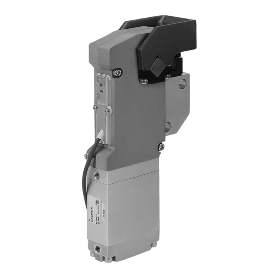
- Page 1 No.D-※S-OMJ0002 CNOMO Standard Compliant Solid State Auto Switch (Proximity Type) PRODUCT NAME D-NF001 D-NF002 MODEL/ Series ...
-
Page 2: Table Of Contents
Contents Safety Instructions Model Indication Method Parts and Functions Description Description and function of each parts Terminology Mounting and Installation Installation Circuit Troubleshooting Specification Specifications Dimensions ... -
Page 3: Safety Instructions
Safety Instructions The solid state auto switch and this manual contain essential information for the protection of users and others from possible injury and property damage and to ensure correct handling. Please confirm that you understand the definition of the following messages (signs) before going on to read the text, and always follow the instructions. - Page 4 Operator ♦This manual has been written for those who have knowledge of machinery and apparatus using pneumatic equipment, and have full knowledge of assembly, operation and maintenance of such equipments. ♦Please read this manual and understand before assembling, operating or providing maintenance work to this product.
- Page 5 NOTE ♦ Follow the instructions given below when designing, selecting and handling your auto switch ♦ Design and Selection (The following installation, wiring, environment of use, adjustment, operation, maintenance and etc. must also be followed.) • Do not place two or more actuators close together. When using more than two actuators mounted parallel with each other, keep 40 mm or more between actuator tubes to prevent influence (malfunction to the auto switch) due to magnetic interference.
- Page 6 • Environment • Never use the auto switch for a corrosive gas or liquid. It can cause failure or malfunction. • Do not use the auto switch in a place where strong magnetic field exists. It can cause a malfunction of the auto switch, or demagnetization of a magnet inside an actuator. •...
-
Page 7: Model Indication Method
Model Indication Method D-NF001 D-NF002 Names and Function of Individual Parts ■Description and function of each parts ■Terminology Terms Meaning and Definition Difference between ON and OFF point which are to prevent chattering. -
Page 8: Mounting And Installation
Mounting and Installation ■Installation Use a screw attached as an accessory to mount a switch on an actuator. ・Proper tightening torque Use special tool or torque wrench for tightening the set screw. M4 mount biss tightening torque shall be 0.5 to 0.9 N •... -
Page 9: Troubleshooting
Troubleshooting Refer the flow chart below for the operation failure of the auto switch. Auto switch failure is possible due to the operating environment (application). For this case, please consult SMC. Wrong selection Detection incorrect Applicable actuator? ... - Page 10 ・Trouble list Trouble Trouble Possible cause Check point Trouble shooting phenomenon of trouble Malfunction due Output stays ON Check the operating environment Effect of magnetic field to turbulence Display stays ON (presence of a welding machine etc.) magnetic field Check the mounting condition of a Wiring failure Correct wiring (See P7 Circuitry)
- Page 11 Trouble Trouble Possible cause Check point Trouble shooting phenomenon of trouble Fix at the right position with right Set position Looseness of switch mounting screw torque displacement Tightening torque : 0.5 to 0.9N • Condition of connecting part Correct wiring Wiring failure ...
-
Page 12: Specification
Specification ■Specifications PLC : Programmable Logic Controller Item Specifications Wiring 2 wire Output − Application 24VDC Relay/PLC Power voltage − Current consumption − Load voltage 24VDC (10 to 28VDC) Load current 2.5 to 100mA Internal voltage drop 5V or less Leakage current 0.6mA or less Indication light... -
Page 13: Dimensions
■Dimensions D-NF001 • -12- No.D-※S-OMJ0002... - Page 14 • D-NF002 -13- No.D-※S-OMJ0002...
- Page 15 Revision history URL http://www.smcworld.com Phone AUSTRIA / (43) 2262-62 280 ITALY / (39) 02-92711 BELGIUM / (32) 3-355 1464 NETHERLANDS / (31) 20-531 8888 CZECH REP. / (420) 5-414 24611 NORWAY / (47) 67 12 90 20 DENMARK / (45) 70 25 29 00 POLAND / (48) 22-548 50 85 FINLAND / (358) 9-859 580 PORTUGAL / (351) 2 610 89 22...
Need help?
Do you have a question about the D-NF001 and is the answer not in the manual?
Questions and answers