Table of Contents
Advertisement
1 • INSTALLATION
• Dimensions and cut-out: Panel mounting
63
48
48
99
10
108
96
48
44,5
105
10
Panel mounting:
Fix the device with the bracket provided before making any electrical connections.
To mount two or more devices side by side, use the cut-out dimensions shown above.
CE MARKING: EMC (electromagnetic compatibility) conformity to EEC Directive
89/336/CEE with reference to the generic Standard EN50082-2 (immunity in industrial
environments) and EN50081-1 (emission in residential environments). BT (low voltage)
conformity to Directive 73/23/CEE as modified by Directive 93/68.
MAINTENANCE: Repairs must be done out only by trained and specialized personnel.
Cut power to the device before accessing internal parts.
Do not clean the case with hydrocarbon-based solvents (Petrol, Trichlorethylene, etc.).
Use of these solvents can reduce the mechanical reliability of the device. Use a cloth
dampened in ethyl alcohol or water to clean the external plastic case.
SERVICE: GEFRAN has a service department. The warranty excludes defects caused
by any use not conforming to these instructions.
81651C_MHW_40B48-96_0308_ENG
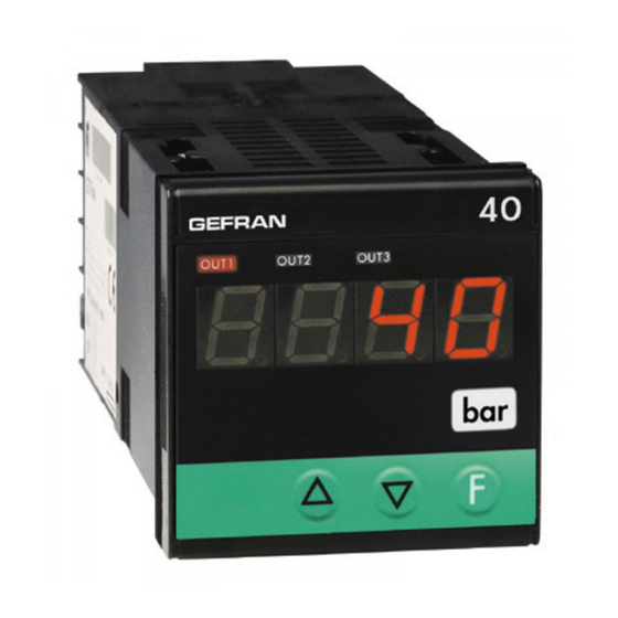
40B 48 / 40B 96
POSITION, FORCE and PRESSURE INDICATOR-INTERCEPTOR
with INPUT for STRAIN-GAUGE and POTENTIOMETER
70
70
45
45
115
70
92
!
For correct and safe
installation, follow the
instructions and observe
the warnings contained
in this manual.
USER'S MANUAL
SOFTWARE VERSION 1.0x / 2.0x
code 81651C / edition 09 - 03/08
2 • TECHNICAL SPECIFICATIONS
Display
Keys
Accuracy
Resolution
Main input
Linear scale ranges
Alarms (set points)
Alarm masking
Relay contact
Logic output
Triac output
(option, only for 96 format)
Fault settings
Analog retransmission (option)
Logic input
Logic input functions
Transmitter / Sensor Power Supply
Power supply (switching)
Fuse (inside device, not
operator serviceable)
Faceplate protection
Working / Storage temperatures
Relative humidity
Installation
Weight
EMC conformity has been tested with the following connections
FUNCTION
Input
Power supply cable
Relay output cables
3, 4 digit red LED's
mod. 48 digit height 10mm (4 digits)
mod. 96 digit height 20mm (3 digits),
digit height 14mm (4 digits)
3 mechanical keys (Raise, Lower, F)
0.2% f.s. at 25°C ambient temperature, ts=120msec
function of settable sample time
>13-bit, s.t. 120 msec. with probe power supply control
>12-bit, s.t. 30 msec.
(60msec with probe power supply control)
>11-bit, s.t. 15 msec.
(30msec with probe power supply control)
Differential input:
- from strain-gauge 350Ω (for pressure, force, etc.),
sensitivity 5mV/V with strain-gauge max power
15V, (7.5mV/V with max power 10V - 15mV/V with
max power 5V), positive or symmetrical
polarization, calibration with automatic calibration
of sensitivity, interrupted probe power signal
- from potentiometer with 1.2V ≥ 100 Ω power
supply
-1999 to 9999 (with 4 digit display)
-999 to 999 (with 3 digit display - only for model 96)
Configurable decimal point position, possible 32
segment linearization
Maximum of three configurable alarms:
absolute, deviation, symmetrical deviation.
Adjustable hysteresis
ability to:
- exclude on power-up
- latch reset from key and/or external contact
- insert delay filter (DON, DBI, DOF, DPO)
- set minimum intervention time
NO (NC) 5A, 250V
11Vdc, Rout = 220Ω (6V/20mA)
20...240Vac ±10%, 3A max
Snubberless, inductive and resistive load (I
2
Alarm states can be configured in probe fault
condition
4 to 20mA, max. 150 Ω load
Ri = 5,6KΩ (24V, 4mA), 1500V isolation
configurable for alarm memory reset, hold, flash,
zero, selection of max., min. peak value, peak-peak
1.2 Vdc for potentiometer > 100 Ω
5 Vdc, 10 Vdc max. 120mA, (for strain-gauge)
15 Vdc, 24 Vdc max. 50mA, (for transmitter)
40B 48 (std) 100...240Vac ±10%, 8VA
(optional) 20...27Vac/dc ±10%, 8VA
40B 96 (std) 100...240Vac/dc ±10%, 10,5VA
(optional) 11...27Vac/dc ±10%, 8VA
100 to 240Vac/dc - type T - 500mA - 250V
11 to 27Vac/dc - type T - 1.25A - 250V
IP65
0 to 50°C / -20 to 70°C
20 to 85%, non-condensing
Panel mounting, extractable from front
160g (mod. 48); 320g (mod. 96) for the complete version
CABLE
LENGTH USED
1 mm
2
3 m
1 mm
2
1 m
1 mm
2
3,5 m
t = 128A
2
s)
1
Advertisement
Table of Contents

Related Manuals for gefran 40B 96


Summarization of Contents
INSTALLATION AND TECHNICAL SPECIFICATIONS
Installation and Panel Mounting
Details physical dimensions, panel cut-out, and correct installation procedures for the device.
Technical Specifications Overview
Lists key technical data including display, input types, resolution, accuracy, and power supply.
FACEPLATE DESCRIPTION AND CONNECTIONS
Faceplate Indicators and Controls
Describes the front panel display, indicators for output states, and the function/navigation keys.
Device Wiring and Connections
Details terminal connections for power supply, inputs (potentiometer, strain-gauge), and outputs.
PROGRAMMING AND CONFIGURATION
Menu Navigation and Parameter Access
Explains how to navigate through the device menus (IF, CF, In, Ou, U.C.) and access parameters.
Input Settings and User Calibration
Covers configuration of input parameters and procedures for user calibration of sensors.
Output and Alarm Configuration
Details settings for output behavior, alarm types, hysteresis, and protection codes.
DETAILED CONFIGURATION PARAMETERS
Input Parameter Settings
Configures probe type, signal range, sampling time, filters, decimal points, and scale limits.
Output Parameter Settings
Configures alarm types, output modes, filter delays, output pulse duration, and fault actions.
ADVANCED CONFIGURATION AND CALIBRATION
Protection, Customization, and Calibration
Details protection codes, custom linearization, and step-by-step user calibration procedures.
SPECIAL FUNCTIONS AND ALARMS
Diagnostic and Logic Input Functions
Explains Eb function for probe interruption, HOLD, and FLASH functions for logic inputs.
Alarm Types and Behavior
Describes absolute and deviation alarms, including normal, symmetrical, and hysteresis behavior.
OUTPUT FILTERING AND CALIBRATION EXAMPLES
Output Filtering Parameters
Details the effect of F.0 and r.A parameters on output filtering and delayed activation/deactivation.
Strain-Gauge Calibration Examples
Provides practical examples for calibrating strain-gauge sensors with positive and symmetrical polarization.
Configuration Hardware and Order Codes
Information on the RS232 interface cable for configuration and product order codes.
ORDER CODE AND WARNINGS
Device Order Code Structure
Details the modular structure for ordering the device with specific sensor power, inputs, and outputs.
General Safety Warnings and Precautions
Important warnings regarding installation, electrical connections, safety, and handling of the device.
Need help?
Do you have a question about the 40B 96 and is the answer not in the manual?
Questions and answers