Table of Contents
Advertisement
Quick Links
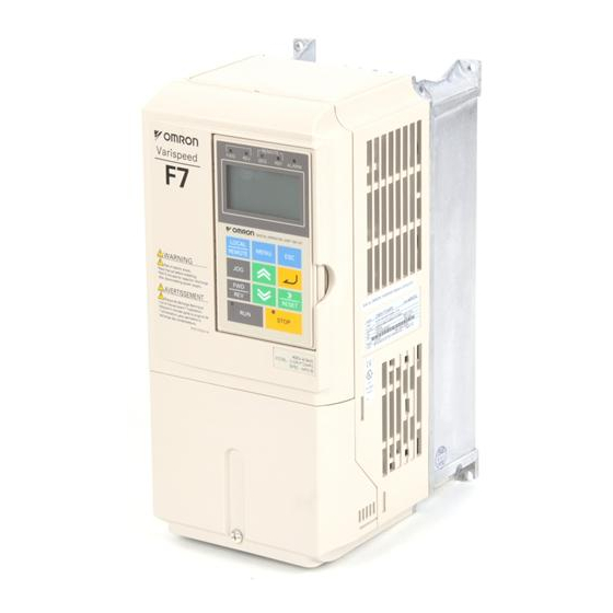
Vector Control Drive
Model: CIMR-F7Z
200V Class, 0.4~110kW (1.2~160kVA)
400V Class, 0.4~300kW (1.4~460kVA)
Application Software Instruction Manual
Software Title
Software Version
Issued Date
Product Name
This is a Special Software for Yaskawa inverter Varispeed F7Z. It can be downloaded to a standard Varispeed F7Z
inverter to provide additional functions, which are described, attached. For all other functions please refer to the Instruction
Manual TOE-S616-55.1
To download this software, please use the download cable "UWR00468-1" between PC and the inverter and execute the
flash memory download program " FlashWrite2000.EXE".
YEG_DMF001B
Crane Software
VSF 107070
16. April 2004
Varispeed F7Z
Software No.VSF107070
Advertisement
Table of Contents

Related Manuals for YASKAWA CIMR-F7Z


Summary of Contents for YASKAWA CIMR-F7Z
- Page 1 Product Name Varispeed F7Z This is a Special Software for Yaskawa inverter Varispeed F7Z. It can be downloaded to a standard Varispeed F7Z inverter to provide additional functions, which are described, attached. For all other functions please refer to the Instruction Manual TOE-S616-55.1...
-
Page 2: Table Of Contents
Table of Contents 1. General Specifications 2. Specification Sheet 3. Connection Diagram 4. Changes with the Standard F7Z Drive 5. Test Run 6. Description of Additional Functions 7. Faults and Counter-Measures (for new and modified faults) Appendix-1: How Parameters are Calculated Appendix-2: Check Point Appendix-3: Tuning Procedure Appendix-4: Parameter Tables... -
Page 4: General Specifications
1. General Specifications The general specifications for the F7Z Crane Drive are based on the information found in the Varispeed F7Z Manual, EZZ009297. (a) For information on how the digital operator works and how Auto-Tuning functions, refer to the Varispeed F7Z Manual (EZZ009297). -
Page 5: Connection Diagram
Braking Resistor Unit (Option) R(L1) U(T1) Emergency Main Varispeed G7 S(L2) V(T2) MS Main T(L3) W(T3) MS Main Circuit Contractor S1 FWD / Stop 3rd Ground S2 REV/ Stop External Fault Analog Monitor 2 Multi-Function Analog Output Fault Reset REV Stop Brake Release Check Analog Monitor 1 F Forward Command... -
Page 6: Changes With The Standard F7Z Drive
4. Changes with the Standard F7Z Drive (parameter table included) 4.1 Changes made from the standard drive: 4.1.1 Function Differences Between the Crane Drive and F7Z Standard Drive Added Functions Deleted Functions Changed Functions Brake Sequence and Brake Operations changed when an external BB command is input Signal Observation Function during run (see section 6.9). - Page 7 4.1.3 Multi-Function Input / Output Functions The initial value for H1-xx and H2-xx in the F7Z Crane drive have been changed as shown below when compared to the standard drive model: Parameter No. Name Standard Drive Crane Drive H1-01 Terminal S3 Function 24 (External Fault) 24 (External Fault) H1-02...
- Page 8 Ultra Lift Overload Detection Over Weight Overtorque Detection Over Torque Changes from Yaskawa’s Standard Drive: *1: Deleted parameter. *2: Parameter for which the initial value was changed. *3: Change in the setting range. *4: Added parameter. Note:Regarding the Parameter Access Level: Q : Quick-Start menu shows the parameter.
- Page 9 Table 4.2.2 Parameter Table (1) Differences with Yaskawa's standard drives are marked with gray shading. Note-2 Chan Parameter Access Level Parameter Name Setting Setting Factory (Digital Operator Comments Memo Range Units Settings Display) OLV CLV Address 0: English 2: German...
- Page 10 Magnetic Flux Sets the magnetic flux compensation b2-08 Compensation Volume as a percentage of the no-load current 190H 1000 (Field Comp) value (E2-03). Droop Control gain 0.0~ b7-01 0.1% 1CAH (Droop Quantity) 100.0 Droop Control Delay 0.03~ 0.01 b7-02 Time 0.05 1CBH 2.00...
- Page 11 Determines if the motor magnetic Output Voltage Limit flux is automatically decreased Operation Selection C3-05 when output voltage saturation 213H (Output V Limit) occurs. 0: Disabled 1: Enabled Torque 0.00~ C4-01 0.01 1.00 215H Compensation Gain 2.50 (Torq Comp Gain) Torque *Factory/default settings will vary Compensation...
- Page 12 Frequency 0.00~ 0.01 d1-08 Reference 8 0.00 287H 150.00 (Reference 8) Frequency 0.00~ 0.01 d1-09 Reference 9 0.00 288H 150.00 (Reference 9) Frequency 0.00~ 0.01 d1-10 Reference 10 0.00 28BH 150.00 (Reference 10) Frequency 0.00~ 0.01 d1-11 Reference 11 0.00 28CH 150.00 (Reference 11)
- Page 13 0~E: Select from 15 preset fixed V/f Pat tern patterns. Selection F : Random Pattern w/Output Voltage E1-03 0~FF 302H (V/f Limit Selection) FF : Random Pattern w/Output Voltage Limit Max Output Frequency 40.0~ 50.0 E1-04 303H (Max 150.0 Frequency) Max Voltage 0.0~ 200.0...
- Page 14 Motor Iron-Core Saturation 0.50~ E2-08 0.01 0.75 315H Coefficient 2 0.75 (Saturation Comp 2) Note: The access level for Open Loop Motor Mechanical 0.0~ Vector Control since E2-09 Loss 0.1% 316H 10.0 VSG126110 has been A (Mechanical Loss) (Advanced). Motor Iron Loss for Torque E2-10 317H...
- Page 15 Table 4.2.2 Parameter Table (6) Chan Note-2 Parameter Access Level Parameter Name Setting Setting Factory (Digital Operator Comments Memo Range Units Settings Display) OLV CLV Address PG Division Rate (PG Pulse Enabled only with PG-B2 Control F1-06 1~132 385H Monitor) Board.
- Page 16 Table 4.2.2 Parameter Table (7) Note-2 Chan Parameter Access Level Parameter Name Setting Setting Factory Memo (Digital Operator Comments Range Units Settings OLV CLV Display) Address Operation Selection after 0: Deceleration Stop 2: Fast Stop F6-01 Communication 3A2H 1: Coast to Stop 3: Alarm Only Error (BUS Fault Sel)
- Page 17 Gain (Terminal 0.0~ H3-10 0.1% 100.0 419H (Terminal A2 1000.0 Gain) Bias (Terminal -100.0 H3-11 0.1% 41AH (Terminal A2 100.0 Bias) Analog Input Filter Time 0.00~ 0.01 H3-12 0.03 41BH Constant 2.00 (Filter Avg Time) Terminal A1/A2 0: Master frequency from terminal A1 H3-13 Suitching 1: Master frequency form terminal A2...
- Page 18 Table 4.2.2 Parameter Table (9) Note-2 Parameter Access Level Parameter Name nges Setting Setting Factory (Digital Operator Comments Memo Range Units Settings Display) OLV CLV Address Train Input H6-01 Function Selection 0: Frequency Reference 42CH (Pulse Input Sel) Pulse Train Input 1000~ H6-02 Scaling...
- Page 19 Speed Agreement Detection Width 0.0~ L4-04 (+/-) 49CH 20.0 (Spd Agree Width Operation When 0: Controls disabled during freq. Frequency reference loss. L4-05 Reference is 49DH 1: Controls enabled during freq. Missing reference loss whth L4-06 fref. (Ref Loss Sel) Frequency When L4-05 is set to 1, L4-05 setting reference when...
- Page 20 Ground Protection 0: Ground protection disabled. L8-09 Selection 4B5H 1: Ground protection enabled. (Ground Fault Sel) 0: Fan On-Run Mode - Fan will Cooling Fan operate only when the Drive is running and for L8-11 seconds Control L8-10 Selection after RUN is removed. 4B6H (FAN Control 1: Fan Always On - Cooling fan...
- Page 21 0: No Change 1: Set Defaults - Saves current User Constant parameter settings as User Initial Value o2-03 Initialization.. 507H (User Defaults) 2: Clear All - Clears the currently saved User Initialization. A1-03 no longer allows selecting *Not reset when the drive is kVA Selection o2-04 0~FF...
- Page 22 REV Run Brake S1-08 Release Torque 687H (Rev Release T) FWD Run Torque Forcing Value (Fwd Torq *Factory/default settings will vary Forcing) based on Control Mode (refer to S1-09 attached table). 688H FWD Run Torque The lower frame is displayed when Compensation -200~ operating in Flux Vector Mode.
- Page 23 Table 4.2.2 Parameter Table (13) Parameters S3-xx through S6-xx were all added to REV-1 Note-2 Parameter Access Level Parameter Name Chang Setting Setting Factory Memo (Digital Operator Comments es on Range Units Settings the Fly V/f OLV CLV Display) Address FWD Run Impact Stop Det ection S3-03...
- Page 24 Light-load Acceleration 2 0.1~ S4-13 Limit Timer 6A8H 10.0 (Pwr Det Time@UL2) Light-load 0: Deceleration Stop Fast Acceleration 2 Fault Operation Stop S4-14 6A9H 1: Coast to Stop 3: Acceleration Selection prohibited (Pwr Det Sel @UL2) Light-load Acceleration 2 Fault Detection S4-15 0~200 100% of the motor rated output.
- Page 25 Table 4.2.2 Parameter Table (14) Parameters S3-xx through S6-xx were all added to REV-1. Note-2 Chan Parameter Access Level Parameter Name Setting Setting Factory Comments (Digital Operator Memo Range Units Settings Display) OLV CLV Address 0: No overload detection. 1: Detection only during Speed Agree, acceleration prohibited (continue running).
- Page 26 0: No overtorque detection 1: Detection only during Speed Agree, acceleration prohibited (continue running). Minor error. 2: Detection while running, acceleration prohibited (continue running). Minor error. 3: Detection only during Speed Agree. Overtorque Detection Interrupt output current. Serious Selection 2 S6-04 error.
- Page 27 Table 4.2.3 Monitor Constants Table (1) ”mark indicates that analog monitor output is disabled Parameter Access Level * Parameter Name Output Signal (Digital Setting Level During Memo Comments Operator Multi-Function Range OLV CLV Display) Analog Output Address Frequency 10V: Max. output U1-01 0.01Hz The unit differs depending on o1-03 setting.
- Page 28 0 0 0 0 0 0 0 0 1: During running 1: During zero speed 1: During reverse 1: During reset Operation signal input Status* U1-12 (Int Ctl Sts 1) 1: During speed agree 1: Inverter operation ready 1: Minor fault 1: Major fault Cumulative U1-13...
- Page 29 Detection Parameter* U1-34 (OPE Parameter) Zero Servo Shows the number of PG pulses times 4 for the U1-35 Movement Pulses movement range when stopped at zero. (Zero Servo Pulse) 0 0 0 0 0 0 0 0 1: CRC error 1: Data length error Not used MEMOBUS...
- Page 30 Table 4.2.3 Monitor Constants Table (3) Parameter Access Level * Output Signal Parameter Name Setting Level During Memo Comments (Digital Operator Multi-Function Range OLV CLV Display) Analog Output Address Current Fault U2-01 (Current Fault) Last Fault U2-02 (Last Fault) Frequency Reference U2-03 at Fault 0.01Hz...
- Page 31 Elapsed Time of 8th U3-18 Fault 811H (Elapsed TIme 8) Elapsed Time of 9th U3-19 Fault 812H (Elapsed TIme 9) Elapsed Time of 10th U3-20 Fault 813H (Elapsed TIme 10) 4.2.3 Multi-Function Input Terminal Functions Any changes made from the standard inverter are indicated by bold outline and gray shading. Multi-Function Output Terminal Setting Multi-Function Input Terminal Functions...
- Page 32 Zero Servo Command 73-76 Speed Control (ASR) Proportional Gain Switch External Torque Polarity Reversal Command Closed Brake Signal 80-FF * Layered setting are not possible, with the exception of OF. 4.2.4 Factory/Default Settings that Change Based on Control Mode (A1-02) Factory Settings Minimum Name...
- Page 33 Note-1: Shows the capacity when working with 1.5kW and under. Note-2: Upper name is used in Vector Mode without PG, and the lower name is used when operating in Flux Vector Control Mode. Note-3: Factory/default settings for E3-02, -03, -04, -05, -06, -07, and -08 will change based on the Control Mode Selection for Motor 2. 4.2.5 (1) Parameters that change based on drive capacity (o2-04): (200V Class) Name...
- Page 34 4.2.5 (2) Parameters that change based on drive capacity (o2-04): (400V Class) Name Units Factory Settings Inverter Capacity 0.75 18.5 E2-11 Motor rated Output E4-07 Motor 2 Rated Output o2-04 Drive/kVA Selection Carrier Frequency C6-02 Selection Upper Limit of Carrier Frequency E2-01 Motor Rated Current...
-
Page 35: Test Run
4.2.5 (3) Parameters that change based on drive capacity (o2-04): (400V Class) Name Units Factory Settings Inverter Capacity E2-11 Motor rated Output E4-07 Motor 2 Rated Output o2-04 Drive/kVA Selection C6-02 Carrier Frequency Selection Upper Limit of Carrier Frequency E2-01 Motor Rated Current 370.0 500.0... -
Page 36: Description Of Additional Functions
6. Description of Additional Functions Areas of Caution Before Use (1) Check that the wiring is set up so that the motor is rotating in reverse (REV) when lowering, and forward (FWD) when hoisting in all control modes. (2) Be sure to set S1-20 to "1" (enabling regen operation while the motor is rotating) when using the crane to lower or hoist the load without a counter-weight (necessary only when running in Open Loop Vector Control... - Page 37 Open Loop Vector Control Mode Speed Cmd Input (Trmnl A1) closed FWD (REV) Command Input open (Terminal S1 (S2) time constant: ITCT ITCF (ITCR) Torque Forcing Amount, C4-02 Output Frequency ↑ Smaller of either FHF (FHR) E1-09 ↓ ↑ b2-01 or E1-09 FRF (FRR) 10UT>IF(IR) closed...
- Page 38 (1) Terminal S1 and S2 (Forward Run Command, Reverse Run Command) The operations shown below are executed when the steady signal is entered based on the combination of the forward and reverse run commands. Operations may be restricted in some way based on the Run Command Tuning Function. For mo re information, see the description listed in section 6.2, “Run Command Tuning Function”...
- Page 39 6.1.2 Stopping Sequence In order to prevent slipping when the drive is stopped, enough torque must be produced to take care of the load until the brake is completely clamped shut. Operation Description (1) If a Stop Command is input (i.e., both the FWD and REV commands are open), then the drive will stop by the method set to parameter b1-03.
- Page 40 6.1.4 Brake Operations via Terminal A1 (Speed Command Input) Time charts up to this point have been when the terminal A1 signal selection (H3-01) has been set to zero (0V to +10V). There, the brake cannot be applied or released by using the Speed Command via terminal A1. In the diagram below, H3-01 has instead been set to "1"...
- Page 41 Operation Description (1) With terminal S1 closed, the larger value (absolute value) between parameters E1-09 (Min Output Freq) and b1-02 (Zero Speed Level) will be input to terminal A1 (Speed Cmd Input). That input will be seen as a Run Command, and the operations discussed in 6.1.1 "Start Sequence"...
- Page 42 6.2 Run Command Tuning 6.2.1 Run Command Minimum ON Time Function The Run command is hold during minimum ON Time (S2-01,-02). Operation Description: When S2-01 (S2-02) ? 0 Doesn’t re-accelerate FWD (REV) Cmd Input Terminal S1 (S2) drive’s internal Run Cmd S2-01 (S2-02) S2-01 (S2-02) not accepted...
- Page 43 6.2.2 Operation Command Delay Timer (Reverse? Forward) If hoisting operations start just after lowering the load in Open Loop Vector or V/f Control Modes, then a large amount of current may flow through the drive. The peak of the output current can be reduced by delaying the hoist operation command.
- Page 44 * If ITR is less than IFOT (IROT) in Vector Control Mode, or if IOUT is less than IFOT (IROT) in V/f Control mode, then the output frequency during FCR will become TCR during run. IOUT : Inverter Output Current BDT : Brake Operation Delay Time ITR : Inverter Torque Command FCR : Impact Stop Clip Frequency (S3 -01)
- Page 45 6.4 Light-load Acceleration Function 6.4.1 Light-load Acceleration 1 Function If the load is detected as being lighter than the amount of the output current or the torque reference, then the frequency reference is increased and the drive continues to run. This can help constrict operation time. This function determines whether or not the acceleration is allowed (Light-load) to the frequency reference that has been set.
- Page 46 The Light-load function is reset by one of the conditions shown below. Once reset, the drive will accelerate until the load is checked again as described in (1). ・ when the Run Command relay is open ・ when the Frequency Reference Input Value is below the Light-load 1 Detection Frequency (FAD) ・...
- Page 47 Light-load Acceleration 2 Function is Enabled Multi-Function Input Function Setting S4-01 Setting Light-load Acceleration Enable / Disable Output frequency does not exceed light load acceleration 2 enabled open Digital frequency (S4 -08) “ 36” is set to H1-01~05 No effect on settings Input closed Light-load acceleration 2 function is enabled.
- Page 48 Light-load Acceleration 2 Fault (OL6) Protection Operation (S4-14) Setting Operations after Detection Fault Type Deceleration to stop (Deceleration by selected deceleration time) Major fault (fault contact output is enabled.) Coast to stop Major fault (fault contact output is enabled.) Deceleration to stop (Deceleration by fast stop time.) Major fault (fault contact output is enabled.) Acceleration prohibited (Operation continues) Minor fault (reset when run command is opened and stopped.)
- Page 49 Multi-Function Output (Overload Detection Signal) Description Name Message Setting Description Overweight Detection Overload detection If conditions for either Overweight Detection 1 or 2 arise, then the output relay will close. (N.O.contact) N.O. It will remain closed for the duration that "OL5" appears on the digital operator screen. Overweight Detectio n Overload Detection If conditions for either Overweight Detection 1 or 2 arise, then the output relay will open.
- Page 50 6.7 Travel Limit Function limit switch for REV limit switch for FWD The Travel Limit Function is a switch that prevents the cart/container from traveling past the target location, and hoisting functions from raising the load up too high. Based on the Multi-Function Input setting, selections can be made for the FWD/REV side, or for N.O./N.C.
- Page 51 2. When switching from Motor 2 to Motor 1, the operations enclosed in brackets will be executed. Motor Switch Control (1) Motor Switch Control is active for approximately 50ms (500ms with a pulse generator) (2) All parameters regarding Control Mode, V/f Characteristics, Motor Parameter functions are re-initialized with Motor 2 (or Motor 1).
-
Page 52: Faults And Counter-Measures (For New And Modified Faults)
7. Description of Fault Display and Fault Counter-Measures (table below contains additional faults.) For counter-measures and other information concerning faults identical to those in Yaskawa ’s standard model drives, please refer to the standard F7 manual. Table 7: Fault Display and Counter-Measures: Additional faults specific to the F7Z-Crane drive... -
Page 53: Appendix-1: How Parameters Are Calculated
The following conditions have not been net or set up: ・When Brake Lag Time (S1 -04) ? 0 and Brake Release Frequency (S1 -01, 02) = Brake Delay Frequency (S1 -03) ・When Slip Prevention Time (S1 -15) ? 0, and OPE22 Brake Release Frequency (S1 -12, 13) = Slip Prevention Frequency Parameter... - Page 54 (5) Brake Release Current IF (S1-05), IR (S1-06) Vector Control: Setting is based on the following equation: (E2-03) × 100 / (E2-01) E2-03 = No Load Current, E2-01 = Motor Rated Current V/f Control Mode: Sets the hoisting load at 100% and the traverse load at 50%. Adjust the setting to be appropriate for the load if the load varies in forwards and reverse.
- Page 55 (18) V/f setting, Torque Compensation Gain KT (C4-01) No need to change when operating in Flux Vector Control. Torque from the motor is proportional to approximately the value of (V/f) If the width of the V/f ratio is changed at low speeds, then insufficient torque will be produced or Over current (overexcitation, etc) is likely to occur during Swift Lift.
- Page 56 (2) When motor data is unknown, then the following formulas are used to set the drive: ・ Identical to the default setting in E1-04~13, KT (C4-01) = 1.0. ・ If any slipping or sequence fault SE2 occurs at start, then increase the value of Vb and Vmin. = DefaultValue + (5V~10V) ? try increasing up to this value Vmin = DefaultValue +...
- Page 57 (29) Swift Lift 2 Limit Timer TA2 (S4-13) If the acceleration hold or acceleration time extension in the high-speed area continues for longer than the time set to the Swift Lift 2 Timer, then acceleration will stop for that period of time. Normally, set between 50% to 100% of the acceleration time in the high speed area.
-
Page 58: Appendix-2: Check Point
Appendix-2: Check List and Trouble Shooting If any error or faults occur during a test run, consult the table below. Problem Cause Counter-Measure(s) Fault OPE11 has occurred. Parameter setting error. See section “7. Faults and Counter-Measures” Fault OPE22 or OPE23 has occurred. Parameter setting error. - Page 59 Problem Cause Counter-Measure(s) ・ B rake Release current, Torque (S1-05~08) ・ D ecrease the Brake Release Current / Torque Brake slips at start. setting is too high. (S1 -05~08). ・ V /f setting is too high. ・ L ower the V/f setting. Refer to, “Appendix-3: Tuning Procedures”.
-
Page 60: Appendix-3: Tuning Procedure
Appendix-3: Tuning Procedures For use with hoisting applications in Open Loop Vector Mode. If fluctuation of output current is too large when performing a test run, then adjust parameters by following the tuning procedure below. When changing parameters, follow the directions give in the column marked, "Setting Instructions". - Page 61 Inverter Parameter Setting Instructions Contents Parameter Number And Name Setting Instruction Brake S1-01: Brake Release Frequency (FWD) Set to 0.6Hz. Sequence Slowly increase this setting if there appears to be fluctuation when S1-02: Brake Release Frequency (REV) lowering the load. Do not set this parameter to be greater than the value in S1 -03.
-
Page 62: Appendix-4: Parameter Tables
Appendix-4: Parameter Table Initial values shown here are for the Open Loop Vector Control Mode, with a 200V 0.4kW drive. Initial Setting Initial Setting Parameter Name Parameter Name Value Value Value Value Language Selection Deceleration Time A1-00 C1-06 10.0 (Select Language) (Decel Time 3) Access Level Acceleration... - Page 63 Appendix-4: Parameter Table [continued] Initial Setting Initial Setting Parameter Name Parameter Name Value Value Value Value ± Speed Limits Carrier Frequency Selection C6-02 d4-02 (Carrier Freq Sel) (Trim Control Lvl) Carrier Frequency Upper Limit Input Voltage Setting C6-03 E1-01 (Carrier Freq Max) (Input Voltage) Carrier Frequency Lower Limit V/f Pattern Selection...
- Page 64 Appendix-4: Parameter Table [continued] Initial Setting Initial Setting Parameter Name Parameter Name Value Value Value Value Motor 2 Mid Output Frequency (FB) Excessive Speed Deviation Detection Level E3-05 F1-10 (Mid Frequency) (PG Deviate Level) Motor 2 Mid Output Frequency Voltage (VC) 12.0 Excessive Speed Deviation Detection Time E3-06...
- Page 65 Appendix-4: Parameter Table [continued] Initial Setting Initial Setting Parameter Name Parameter Name Value Value Value Value Signal Level Selection (Terminal A1) Pulse Train Input Bias H3-01 H6-04 (Term A1 Signal) (Pulse Train Input Bias) Gain (Terminal A1) Pulse Train Input Filter Time H3-02 H6-05 100.0...
- Page 66 Appendix-4: Parameter Table [continued] Initial Setting Initial Setting Parameter Name Parameter Name Value Value Value Value Protection Selection for Internal DB Operation Selection when Digital Operator L8-01 o2-06 Resistor (Type ERF) is Disconnected (DB Resistor Prot) (Oper Detection) Overheat Pre-Alarm Level Cumulative Operation Time Set ting L8-02 o2-07...
- Page 67 Appendix-4: Parameter Table [continued] Initial Setting Initial Setting Parameter Name Parameter Name Value Value Value Value Light-load Acceleration 2 Fault Detection Reverse Operations S1-20 S4-15 Level (Action @Reverse) (Pwr Det Lvl @UL2) Light-load Acceleration 2 Fault Detection FWD Run Command Min. ON Time S2-01 S4-16 Time...
Need help?
Do you have a question about the CIMR-F7Z and is the answer not in the manual?
Questions and answers