YASKAWA Varispeed F7 Instruction Manual
Current vector controlled, general-purpose inverter
Hide thumbs
Also See for Varispeed F7:
- Instruction manual (463 pages) ,
- User manual (256 pages) ,
- Programming manual (202 pages)

Related Manuals for YASKAWA Varispeed F7


Summary of Contents for YASKAWA Varispeed F7
- Page 1 Current Vector Controlled, General-Purpose Inverter Varispeed F7 Instruction Manual and Parameter Description Model: CIMR-F7Z YEG -TOE-S616-55.1...
-
Page 3: Table Of Contents
EMC Compatibility ................XII Schaffner Line Filters ................ XIV Registered Trademarks ..............XVII Handling Inverters..............1-1 Varispeed F7 Introduction................1-2 Varispeed F7 Applications ....................1-2 Varispeed F7 Models ...................... 1-2 Confirmations upon Delivery ................1-4 Checks..........................1-4 Nameplate Information ....................1-4 Component Names......................1-5 Exterior and Mounting Dimensions ..............1-8... - Page 4 Main Circuit Terminal Functions................... 2-12 Main Circuit Configurations ..................2-13 Standard Connection Diagrams ................... 2-14 Wiring the Main Circuits....................2-15 Wiring Control Circuit Terminals..............2-22 Wire Sizes ........................2-22 Control Circuit Terminal Functions ................2-24 Control Circuit Terminal Connections................2-27 Control Circuit Wiring Precautions ................
- Page 5 No-load Operation ......................4-13 Loaded Operation ......................4-14 Check and Recording Parameters................4-14 Adjustment Suggestions................4-16 User Parameters............... 5-1 User Parameter Descriptions .................5-2 Description of User Parameter Tables ................5-2 Digital Operation Display Functions and Levels ..........5-3 User Parameters Setable in Quick Programming Mode..........5-4 User Parameter Tables...................5-7 A: Setup Settings ......................
- Page 6 Accelerating and Decelerating Heavy Loads (Dwell Function) ........6-22 Preventing the Motor from Stalling During Acceleration (Stall Prevention During Acceleration Function) ............6-23 Preventing Overvoltage During Deceleration ............... 6-24 Adjusting Frequency References ..............6-26 Adjusting Analog Frequency References ..............6-26 Operation Avoiding Resonance (Jump Frequency Function)........
- Page 7 Blocking Inverter Outputs (Baseblock Commands) ............6-64 OH2 (Overheat) Alarm Signal Input................6-65 Multifunction Analog Input A2 Disable/Enable..............6-65 Drive Enable/Disable ....................6-66 Stopping Acceleration and Deceleration (Acceleration/Deceleration Ramp Hold) ..6-66 Raising and Lowering Frequency References Using Contact Signals (UP/DOWN)..6-68 Adding/Subtacting a Fixed Speed to an Analog Reference (Trim Control) ....6-70 Hold Analog Frequency Using User-set Timing............6-71 Switching Operation Source to Communication Option Card........
- Page 8 Troubleshooting ................7-1 Protective and Diagnostic Functions.............. 7-2 Fault Detection ....................... 7-2 Alarm Detection......................7-9 Operator Programming Errors..................7-13 Auto-tuning Fault ......................7-15 Digital Operator Copy Function Faults ................. 7-16 Troubleshooting ................... 7-18 If A Parameter Cannot Be Set..................7-18 If the Motor Does Not Operate Properly............... 7-19 If the Direction of the Motor Rotation is Reversed............
- Page 9 Appendix ................. 10-1 Inverter Application Precautions..............10-2 Selection ........................10-2 Installation........................10-3 Settings.........................10-3 Handling........................10-4 Motor Application Precautions..............10-5 Using the Inverter for an Existing Standard Motor ............10-5 Using the Inverter for Special Motors ................10-6 Power Transmission Mechanism (Speed Reducers, Belts and Chains).......10-6 User Constants.....................10-7...
- Page 10 VIII...
-
Page 11: Warnings
Cables must not be connected or disconnected, nor signal tests carried out, while the power is switched on. The Varispeed F7 DC bus capacitor remains charged even after the power has been switched off. To avoid an electric shock hazard, disconnect the frequency inverter from the mains before carrying out maintenance. -
Page 12: Safety Precautions And Instructions For Use
Safety Precautions and Instructions for Use 1. General Please read these safety precautions and instructions for use thoroughly before installing and operating this inverter. Also read all of the warning signs on the inverter and ensure they are never damaged or removed. Live and hot inverter components may be accessible during operation. - Page 13 In certain systems it may be necessary to use additional monitoring and safety devices in compliance with the relevant safety and accident prevention regulations. The frequency inverter hardware must not be modified. 6. Notes The VARISPEED F7 frequency inverters are certified to CE, UL, and c-UL.
-
Page 14: Emc Compatibility
EMC Compatibility 1. Introduction This manual was compiled to help system manufacturers using YASKAWA frequency inverters to design and install electrical switchgear. It also describes the measures necessary to comply with the EMC Directive. The manual's installation and wiring instructions must therefore be followed. - Page 15 Ground clip Ground plate The grounding surfaces must be highly conductive bare metal. Remove any coats of varnish and paint. – Ground the cable shields at both ends. – Ground the motor of the machine. XIII...
-
Page 16: Schaffner Line Filters
Schaffner Line Filters Recommended Line Filters for Varispeed F7 made by Schaffner EMV AG Inverter Model Line Filter (Schaffner) Current Weight Dimensions Varispeed F7 Model 55011 (kg) W x D x H Class* CIMR-F7C40P4 B, 50 m CIMR-F7C40P7 B, 50 m... - Page 17 Line Filters (Schaffner) Current Weight Dimensions Varispeed F7 Type 55011 (kg) W x D x H Class CIMR-F7C20P4 CIMR-F7C20P7 FS 5972-10-07 141 x 45 x 330 CIMR-F7C21P5 CIMR-F7C22P2 FS 5972-18-07 141 x 46 x 330 CIMR-F7C23P7 FS 5973-35-07 141 x 46 x 330...
- Page 18 Installation inverters and EMC filters Ground Bonds ( remove any paint ) Line Inverter Filter Load PE L1 Cable Length as short as possible Metal Plate Motor cable screened Ground Bonds ( remove any paint )
-
Page 19: Registered Trademarks
Registered Trademarks The following registered trademarks are used in this manual. DeviceNet is a registered trademark of the ODVA (Open DeviceNet Vendors Association, • Inc.). InterBus is a registered trademark of Phoenix Contact Co. • Profibus is a registered trademark of Siemens AG. •... - Page 20 XVIII...
-
Page 21: Handling Inverters
Handling Inverters This chapter describes the checks required upon receiving or installing an Inverter. Varispeed F7 Introduction ............1-2 Confirmations upon Delivery..........1-4 Exterior and Mounting Dimensions ........1-8 Checking and Controlling the Installation Site ..... 1-11 Installation Orientation and Space ........1-12 Removing and Attaching the Terminal Cover.......1-13... -
Page 22: Varispeed F7 Introduction
4-1, Trial Operation Varispeed F7 Models es: 200 V and 400 V. The maximum motor capacities The Varispeed F7 Series includes Inverters in two voltage class vary from 0.55 to 300 kW (42 models). Table 1.1 Varispeed F7 Models... - Page 23 Varispeed F7 Introduction Specifications Varispeed F7 (Always specify through the protective structure when ordering.) Maximum Voltage Motor Output Open Chassis Enclosed Wall-mounted Class Capacity kW Capacity Basic Model Number (IEC IP00) (IEC IP20, NEMA 1) CIMR-F7Z CIMR-F7Z 0.55 CIMR-F7Z40P4 40P41 0.75...
-
Page 24: Confirmations Upon Delivery
Confirmations upon Delivery Checks Check the following items as soon as the Inverter is delivered. Table 1.2 Checks Item Method Has the correct model of Inverter been Check the model number on the nameplate on the side of the Inverter. delivered? Inspect the entire exterior of the Inverter to see if there are any scratches or Is the Inverter damaged in any way? -
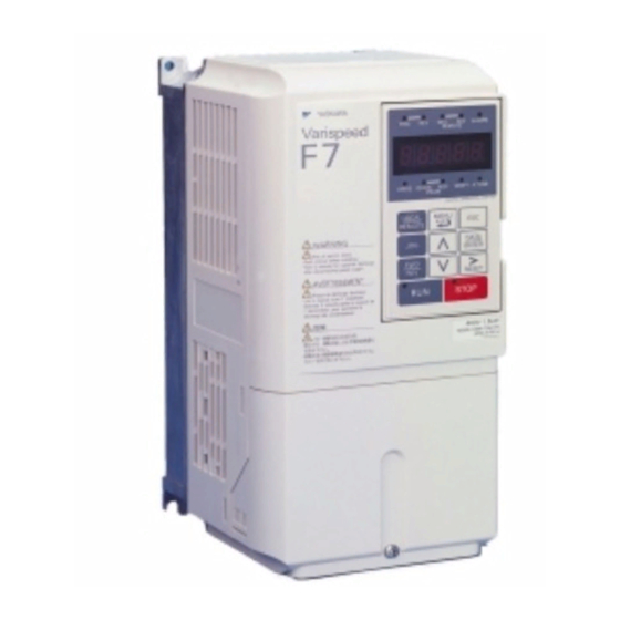
Page 25: Component Names
The model number of the Inverter on the nameplate indicates the specification, voltage class, and maximum motor capacity of the Inverter in alphanumeric codes. CIMR – F7 Z 2 0 P4 Inverter Varispeed F7 Specification Max. Motor Capacity OYMC Europ. Std. - Page 26 Top protective cover (Part of Enclosed Wall- mounted Type (IEC IP20, NEMA Type 1) Mounting Front cover Digital Operator Diecast case Nameplate Terminal cover Bottom protective cover Fig 1.4 Inverter Appearance (18.5 kW or Less) Control circuit terminals Main circuit terminals Charge indicator Ground terminal Fig 1.5 Terminal Arrangement (18.5 kW or Less)
- Page 27 Confirmations upon Delivery Inverters of 22 kW or More The external appearance and component names of the Inverter are shown in 1.6. The Inverter with the ter- minal cover removed is shown in 1.7. Mounting holes Inverter cover Cooling fan Front cover Digital Operator Nameplate...
-
Page 28: Exterior And Mounting Dimensions
Exterior and Mounting Dimensions Open Chassis Inverters (IP00) Exterior diagrams of the Open Chassis Inverters are shown below. 200 V Class Inverters of 22 or 110 kW 200 V/400 V Class Inverters of 0.55 to 18.5 kW 400 V Class Inverters of 22 to 160 kW 400 V Class Inverters of 185 to 300 kW... -
Page 29: Enclosed Wall-Mounted Inverters (Nema1)
Exterior and Mounting Dimensions Fig 1.8 Exterior Diagrams of Open Chassis Inverters Enclosed Wall-mounted Inverters (NEMA1) Exterior diagrams of the Enclosed Wall-mounted Inverters (NEMA1) are shown below. Grommet 200 V/400 V Class Inverters of 0.55 to 18.5 kW 200 V Class Inverters of 22 or 75 kW 400 V Class Inverters of 22 to 160 kW Fig 1.9 Exterior Diagrams of Enclosed Wall-mounted Inverters... - Page 30 Table 1.3 Inverter Dimensions (mm) and Masses (kg) of 200V Class Inverters and 400V Class Inverters of 0.55 to 160 kW Caloric Max. Dimensions (mm) Value(W) Appli- Voltage cable Cool- Open Chassis (IP00) Enclosed Wall-mounted (NEMA1) Total Heat Class Motor Exter Inter- Method...
-
Page 31: Checking And Controlling The Installation Site
Checking and Controlling the Installation Site Checking and Controlling the Installation Site Install the Inverter in the installation site described below and maintain optimum conditions. Installation Site Install the Inverter under the following conditions in a pollution degree 2 environment. Table 1.5 Installation Site Type Ambient Operating Temperature... -
Page 32: Installation Orientation And Space
Installation Orientation and Space Install the Inverter vertically so as not to reduce the cooling effect. When installing the Inverter, always provide the following installation space to allow normal heat dissipation. 30 mm min. 120 mm min. 30 mm min. 50 mm min. -
Page 33: Removing And Attaching The Terminal Cover
Removing and Attaching the Terminal Cover Removing and Attaching the Terminal Cover Remove the terminal cover to wire cables to the control circuit and main circuit terminals. Removing the Terminal Cover Inverters of 18.5 kW or Less Loosen the screw at the bottom of the terminal cover, press in on the sides of the terminal cover in the direc- tions of arrows 1, and then lift up on the terminal in the direction of arrow 2. -
Page 34: Removing/Attaching The Digital Operator And
Removing/Attaching the Digital Operator and Front Cover Inverters of 18.5 kW or Less To attach optional cards or change the terminal card connector, remove the Digital Operator and front cover in addition to the terminal cover. Always remove the Digital Operator from the front cover before removing the front cover. - Page 35 Removing/Attaching the Digital Operator and Front Cover Removing the Front Cover Press the left and right sides of the front cover in the directions of arrows 1 and lift the bottom of the cover in the direction of arrow 2 to remove the front cover as shown in the following illustration. Fig 1.14 Removing the Front Cover (Model CIMR-F7Z45P5 Shown Above) Mounting the Front Cover After wiring the terminals, mount the front cover to the Inverter by performing the steps to remove the front...
-
Page 36: Inverters Of 22 Kw Or More
Fig 1.15 Mounting the Digital Operator 1. Do not remove or attach the Digital Operator or mount or remove the front cover using methods other than those described above, otherwise the Inverter may break or malfunction due to imperfect contact. 2. - Page 37 Removing/Attaching the Digital Operator and Front Cover Fig 1.16 Removing the Front Cover (Model CIMR-F7Z2022 Shown Above) Attaching the Front Cover After completing required work, such as mounting an optional card or setting the terminal card, attach the front cover by reversing the procedure to remove it. 1.
-
Page 39: Wiring
Wiring This chapter describes wiring terminals, main circuit terminal connections, main circuit termi- nal wiring specifications, control circuit terminals, and control circuit wiring specifications. Connections to Peripheral Devices......2-2 Connection Diagram ............2-3 Terminal Block Configuration ........2-5 Wiring Main Circuit Terminals ........2-6 Wiring Control Circuit Terminals ........ -
Page 40: Connections To Peripheral Devices
Connections to Peripheral Devices Examples of connections between the Inverter and typical peripheral devices are shown in 2.1. Power supply Molded-case circuit breaker Magnetic con- tactor (MC) AC reactor for power factor improvement Braking resistor Input noise filter DC reactor for power factor improvement Inverter Ground... -
Page 41: Connection Diagram
U/T1 3-phase power S/L2 V/T2 380 to 480 V Line 50/60 Hz Filter T/L3 W/T3 Varispeed F7 CIMR- F7C47P5 Forward Run/Stop Fault contact output 250 VAC, 1A max. Reverse Run/Stop 30 VDC, 1A max. External fault Fault reset Contact output 1... -
Page 42: Circuit Descriptions
Circuit Descriptions Refer to the numbers indicated in 2.2. These circuits are hazardous and are separated from accessible surfaces by protective separation These circuits are separated from all other circuits by protective separation consisting of double and reinforced insulation. These circuits may be interconnected with SELV (or equivalent) or non- SELV circuits, but not both. -
Page 43: Terminal Block Configuration
Terminal Block Configuration Terminal Block Configuration The terminal arrangements are shown in Fig 2.3 2.4. Control circuit terminals Main circuit terminals Charge indicator Ground terminal Fig 2.3 Terminal Arrangement (200 V/400 V Class Inverter of 0.4 kW) Control Control circuit circuit terminals terminals... -
Page 44: Wiring Main Circuit Terminals
Wiring Main Circuit Terminals Applicable Wire Sizes and Closed-loop Connectors Select the appropriate wires and crimp terminals from Table 2.1 Table 2.3. Refer to instruction manual TOE-C726-2 for wire sizes for Braking Resistor Units and Braking Units. Table 2.1 200 V Class Wire Sizes Recom- Possible Inverter... - Page 45 Wiring Main Circuit Terminals Recom- Possible Inverter Tightening mended Termi- Wire Sizes Model Terminal Symbol Torque Wire Size Wire Type Screws CIMR- (N•m) (AWG) (AWG) 60 to 100 R/L1, S/L2, T/L3, 1 U/T1, 17.6 to 22.5 (2/0 to 4/0) (2/0) V/T2, W/T3, R1/L11, S1/L21, T1/L31 5.5 to 22 8.8 to 10.8...
- Page 46 Table 2.2 400 V Class Wire Sizes Recom- Possible Inverter Tightening mended Termi- Wire Sizes Wire Size Model Terminal Symbol Torque Wire Type Screws CIMR- (N•m) (AWG) (AWG) R/L1, S/L2, T/L3, 2, B1, B2, 2 to 5.5 F7Z40P4 1.2 to 1.5 U/T1, V/T2, W/T3 (14 to 10) (14)
- Page 47 Wiring Main Circuit Terminals Recom- Possible Inverter Tightening mended Termi- Wire Sizes Model Terminal Symbol Torque Wire Size Wire Type Screws CIMR- (N•m) (AWG) (AWG) 38 to 60 R/L1, S/L2, T/L3, 1, U/T1, V/T2, W/ 9.0 to 10.0 (2 to 1/0) T3, R1/L11, S1/L21, T1/L31 8 to 22 F7Z4045...
- Page 48 Recom- Possible Inverter Tightening mended Termi- Wire Sizes Model Terminal Symbol Torque Wire Size Wire Type Screws CIMR- (N•m) (AWG) (AWG) 100 to 325 150 × 2P R/L1, S/L2, T/L3 78.4 to 98 (300 × 2P) (4/0 to 600) 100 to 325 125 ×...
- Page 49 Wiring Main Circuit Terminals Table 2.3 Lug Sizes (JIS C2805) (200 V Class and 400 V Class) Terminal Screws Size Wire Thickness (mm M3.5 1.25 / 3.5 1.25 / 4 M3.5 1.25 / 3.5 0.75 1.25 / 4 M3.5 1.25 / 3.5 1.25 1.25 / 4 M3.5...
-
Page 50: Main Circuit Terminal Functions
Main Circuit Terminal Functions Main circuit terminal functions are summarized according to terminal symbols in Table 2.4. Wire the termi- nals correctly for the desired purposes. Table 2.4 Main Circuit Terminal Functions (200 V Class and 400 V Class) Model: CIMR-F7Z Purpose Terminal Symbol 200 V Class... -
Page 51: Main Circuit Configurations
Wiring Main Circuit Terminals Main Circuit Configurations The main circuit configurations of the Inverter are shown in Table 2.5. Table 2.5 Inverter Main Circuit Configurations 200 V Class 400 V Class CIMR-F7Z20P4 to 2018 CIMR-F7Z40P4 to 4018 Power Control Power Control supply circuits... -
Page 52: Standard Connection Diagrams
Standard Connection Diagrams Standard Inverter connection diagrams are shown in 2.5. These are the same for both 200 V Class and 400 V Class Inverters. The connections depend on the Inverter capacity. CIMR-F7Z20P4 to 2018 and 40P4 to CIMR-F7Z2022, 2030, and 4022 to 4055 4018 Unit (optional) DC reactor... -
Page 53: Wiring The Main Circuits
Wiring Main Circuit Terminals Wiring the Main Circuits This section describes wiring connections for the main circuit inputs and outputs. Wiring Main Circuit Inputs Observe the following precautions for the main circuit power supply input. Installing Fuses To protect the inverter, it is recommended to use semiconductor fuses like they are shown in the table below. Table 2.6 Input Fuses Inverter Type FUSE... - Page 54 Installing a Moulded-case Circuit Breaker When connecting the power input terminals (R/L1, S/L2, and T/L3) to the power supply using a moulded-case circuit breaker (MCCB) observe that the circuit breaker is suitable for the Inverter. Choose an MCCB with a capacity of 1.5 to 2 times of the inverter's rated current. •...
- Page 55 Wiring Main Circuit Terminals Wiring the Output Side of Main Circuit Observe the following precautions when wiring the main output circuits. Connecting the Inverter and Motor Connect output terminals U/T1, V/T2, and W/T3 respective to the motor lead wires U, V, and W. Check that the motor rotates forward with the forward run command.
- Page 56 Cable Length between Inverter and Motor If the cable between the Inverter and the motor is long, the high-frequency leakage current will increase, caus- ing the Inverter output current to increase as well. This may affect peripheral devices. To prevent this, adjust the carrier frequency (set in C6-01, C6-02) as shown in Table 2.7.
- Page 57 Wiring Main Circuit Terminals Connecting a Braking Resistor (ERF) A Braking Resistor mounted to the Inverter can be used with 200 V and 400 V Class Inverters with outputs from 0.4 to 11 kW. Connect the braking resistor as shown in 2.7.
- Page 58 To prevent the braking unit/braking resistor from overheating, design the control circuit to turn OFF the power supply using the thermal overload relay contacts of the units as shown in 2.8. 200 V and 400 V Class Inverters with 0.4 to 18.5 kW Output Capacity Braking Resistor Unit (LKEB) Thermal overload Inverter...
- Page 59 Wiring Main Circuit Terminals Thermal overload relay contact Thermal overload relay contact Thermal overload relay contact Braking Braking Braking Resistor Resistor Resistor Unit Unit Unit (LKEB) (LKEB) (LKEB) Inverter Braking Unit #3 Braking Unit #2 Braking Unit #1 Thermal overload relay Thermal overload relay Thermal overload relay contact...
-
Page 60: Wiring Control Circuit Terminals
Wiring Control Circuit Terminals Wire Sizes For remote operation using analog signals, keep the control line length between the Analog Operator or oper- ation signals and the Inverter to 50 m or less, and separate the lines from main power lines or other control cir- cuits to reduce induction from peripheral devices. - Page 61 Wiring Control Circuit Terminals Wiring Method Use the following procedure to connect wires to the terminal block. 1. Loosen the terminal screws with a thin-slot screwdriver. 2. Insert the wires from underneath the terminal block. 3. Tighten the terminal screws firmly. Screwdriver Blade of screwdriver Control circuit...
-
Page 62: Control Circuit Terminal Functions
Control Circuit Terminal Functions The functions of the control circuit terminals are shown in Table 2.12. Use the appropriate terminals for the correct purposes. Table 2.12 Control Circuit Terminals with default settings Signal Name Function Signal Level Type Forward run/stop command Forward run when ON;... - Page 63 Wiring Control Circuit Terminals Table 2.12 Control Circuit Terminals with default settings (Continued) Signal Name Function Signal Level Type 0 to 32 kHz (3 kΩ) H6-01 (Frequency reference input) High level voltage 3.5 to Pulse input Pulse 13.2 V 0 to 32 kHz Pulse monitor H6-06 (Output frequency) +5 V output (2.2 kΩ)
- Page 64 The functions of DIP switch S1 and jumper CN15 are shown in the following table. Table 2.13 DIP Switch S1 and jumper CN15 Name Function Setting RS-485 and RS-422 terminating resis- OFF: No terminating resistance S1-1 ON: Terminating resistance of 110 Ω tance V: 0 to 10 V (internal resistance: 20 kΩ) S1-2...
-
Page 65: Control Circuit Terminal Connections
Wiring Control Circuit Terminals Control Circuit Terminal Connections Connections to Inverter control circuit terminals are shown in 2.14. ≈ ≈ Forward Run/Stop Fault contact output 250 VAC, 1A max. Reverse Run/Stop 30 VDC, 1A max. External fault Fault reset Contact output 1 Multi-function [Default : Running] Multi-step speed setting 1... -
Page 66: Control Circuit Wiring Precautions
Control Circuit Wiring Precautions Observe the following precautions when wiring control circuits. Separate control circuit wiring from main circuit wiring (terminals R/L1, S/L2, T/L3, B1, B2, U/T1, V/T2, • W/T3, 2, and 3) and other high-power lines. Separate wiring for control circuit terminals MA, MB, MC, M1, M2, M3, M4, M5, and M6 (contact out- •... -
Page 67: Wiring Check
Wiring Check Wiring Check Checks Check all wiring after wiring has been completed. Do not perform continuity check on control circuits. Per- form the following checks on the wiring. Is all wiring correct? • Have no wire clippings, screws, or other foreign material been left? •... -
Page 68: Installing And Wiring Option Cards
Installing and Wiring Option Cards Option Card Models and Specifications Up to two Option Cards can be mounted in the Inverter. You can mount up one card into each of the two places on the controller card (A, and C) shown in 2.15. - Page 69 Installing and Wiring Option Cards Preventing A and C Option Card Connectors from Rising After installing an Option Card into slot A or C, insert an Option Clip to prevent the side with the connector from rising. The Option Clip can be easily removed by holding onto the protruding portion of the Clip and pulling it out.
-
Page 70: Pg Speed Control Card Terminals And Specifications
PG Speed Control Card Terminals and Specifications PG-B2 The terminal specifications for the PG-B2 are given in the following table. Table 2.16 PG-B2 Terminal Specifications Terminal Contents Specifications 12 VDC (±5%), 200 mA max. Power supply for pulse generator 0 VDC (GND for power supply) H: +8 to 12 V (max. -
Page 71: Wiring
Installing and Wiring Option Cards Wiring Wiring the PG-B2 The following illustrations show wiring examples for the PG-B2 using the option cards power supply or an external power source for supplying the PG. Three-phase Inverter VAC (400 VAC) R/L1 S/L2 T/L3 Power supply +12 V Power supply 0 V... - Page 72 PG power supply +12 V Pulse monitor output phase A A-phase pulses Pulse input phase A Pulse monitor output phase B B-phase Pulse input pulses phase B • When connecting to a voltage-output-type PG (encoder), select a PG that has an output impedance with a current of at least 12 mA to the input circuit photocoupler (diode).
-
Page 73: Wiring Terminal Blocks
Installing and Wiring Option Cards Fig 2.20 PG-X2 Wiring Using a 5 V External Power Supply • Shielded twisted-pair wires must be used for signal lines. • Do not use the pulse generator's power supply for anything other than the pulse generator (encoder). Using it for another purpose can cause malfunctions due to noise. - Page 74 Cable Lug Connector Sizes and Tightening Torque The lug sizes and tightening torques for various wire sizes are shown in Table 2.19. Table 2.19 Cable Lugs and Tightening Torques Terminal Tightening Torque (N • m) Crimp Terminal Size Wire Thickness [mm Screws 1.25 - 3.5 0.75...
-
Page 75: Digital Operator And Modes
Digital Operator and Modes This chapter describes Digital Operator displays and functions, and provides an overview of operating modes and switching between modes. Digital Operator and Modes..........3-1 Modes ................3-4... -
Page 76: Digital Operator
Digital Operator This section describes the displays and functions of the Digital Operator. Digital Operator Display The key names and functions of the Digital Operator are described below. Drive Status Indicators FWD: Lights up when a forward run command is input. - Page 77 Digital Operator Table 3.1 Key Functions (Continued) Name Function Enables jog operation when the Inverter is operated from the Digital JOG Key Operator. Selects the rotation direction of the motor when the Inverter is oper- FWD/REV Key ated from the Digital Operator. Sets the active digit when programming parameters.
-
Page 78: Modes
Modes This section describes the Inverter's modes and switching between modes. Inverter Modes The Inverter's parameters and monitoring functions are organized in groups called modes that make it easier to read and set parameters.The Inverter is equipped with 5 modes. The 5 modes and their primary functions are shown in the Table 3.2. -
Page 79: Switching Modes
Modes Switching Modes The mode selection display will appear when the MENU key is pressed. Press the MENU key from the mode selection display to switch through the modes in sequence. Press the DATA/ENTER key to enter a mode and to switch from a monitor display to the setting display. Display at Startup -DRIVE- Frequency Ref... -
Page 80: Drive Mode
Drive Mode The Drive mode is the mode in which the Inverter can be operated. All monitor parameters (U1- ) as well as fault information and the fault history can be displayed in this mode When b1-01 (Reference selection) is set to 0, the frequency can be changed from the frequency setting display using the Increment, Decrement, and Shift/RESET keys. -
Page 81: Quick Programming Mode
Modes Note: 1. When changing the display with the Increment / Decrement keys, the next display after the one for the last parameter number will be the one for the first parameter number and vice versa. For example, the next display after the one for U1-01 will be U1-40. This is indicated in the figures by the letters A and B and the numbers 1 to 6. -
Page 82: Advanced Programming Mode
Advanced Programming Mode In advanced programming mode all Inverter parameters can be monitored and set. A parameter can be changed from the setting displays using the Increment, Decrement, and Shift/RESET keys. The parameter will be saved and the display will return to monitor display when the DATA/ENTER key is pressed after changing the setting. - Page 83 Modes Setting Parameters Here the procedure to change C1-01 (Acceleration Time 1) from 10 s to 20 s is shown. Table 3.3 Setting Parameters in Advanced Programming Mode Step Digital Operator Display Description -DRIVE- Frequency Ref U1- 01=60.00Hz Power supply turned ON. U1-02=60.00Hz U1-03=10.05A -DRIVE-...
-
Page 84: Verify Mode
Verify Mode The Verify mode is used to display any parameters that have been changed from their default settings in a pro- gramming mode or by autotuning. “None” will be displayed if no settings have been changed. The parameter A1-02 is the only parameter from the A1- group, which will be displayed in the modified contsant list if it has been changed before. -
Page 85: Autotuning Mode
Modes Autotuning Mode Autotuning automatically measures and sets the required motor data in order to achieve the maximum perfor- mance. Always perform autotuning before starting operation when using the vector control modes. When V/f control has been selected, only stationary autotuning for line-to-line resistance can be selected. When the motor cannot be disconnected from the load, and Open Loop or Closed Loop Vector Control shall be used perform stationary autotuning. -
Page 87: Trial Operation
Trial Operation This chapter describes the procedures for trial operation of the Inverter and provides an example of trial operation. Trial Operation Procedure..........4-2 Trial Operation .............4-3 Adjustment Suggestions ..........4-16... -
Page 88: Trial Operation Procedure
Trial Operation Procedure Perform trial operation according to the following flowchart. When setting the basic parameters, always set C6-01 (Heavy/Normal Duty Selection) according to the application. START Installation Wiring Set power supply voltage jumper. Turn ON power. Confirm status. Basic settings Select operating (Quick programming mode) method. -
Page 89: Trial Operation
Trial Operation Trial Operation Application Confirmation For applications with quadratic torque characteristic like pumps, fans or blowers set C6-01 (Heavy/Normal Duty selection) to 1 or 2 (Normal Duty 1 or 2). Select the Normal Duty mode (1 or 2) regarding the required overload capability. -
Page 90: Power On
Power ON Confirm all of the following items and then turn ON the power supply. Check that the power supply is of the correct voltage. • 200 V class: 3-phase 200 to 240 VDC, 50/60 Hz 400 V class: 3-phase 380 to 480 VDC, 50/60 Hz Make sure that the motor output terminals (U, V, W) and the motor are connected correctly. -
Page 91: Basic Settings
Trial Operation Basic Settings Switch to the quick programming mode (“QUICK” will be displayed on the LCD screen) and set the follow- ing parameters. Refer to Chapter 3 Digital Operator and Modes for Digital Operator operating procedures and to Chapter 5 User Parameters Chapter 6 Parameter Settings by Function for details on the parameters. - Page 92 Table 4.1 Basic Parameter Settings (Continued) : Must be set. : Set as required. Parame- Setting Factory Class ter Num- Name Description Page Range Setting d1-01 to Frequency refer- d1-01 to d1-16: ences 1 to 16 and Sets the required speed references for 0 to 150.00 Hz 5-24 d1-16 and...
-
Page 93: Settings For The Control Methods
Trial Operation Settings for the Control Methods The usable Autotuning methods depend on the control method setting of the the Inverter. Overview of Settings Make the required settings in quick programming mode and autotuning mode according to 4.1. Setting the Control Method Select the appropriate control mode as required by the application. -
Page 94: Autotuning
Open Loop Vector Control (A1-02 = 2) Always perform autotuning. If the motor can be operated, perform rotating autotuning. If the motor cannot be operated, perform non-rotating autotuning. Refer to the following section on Autotuning for details on auto- tuning. Closed Loop Vector Control (A1-02=3) Always perform autotuning. - Page 95 Trial Operation Precautions Before Using Autotuning Read the following precautions before using autotuning. Autotuning an Inverter is fundamentally different from autotuning a servo system. Inverter autotuning • automatically adjusts parameters according to detected motor data, whereas servo system autotuning adjusts parameters according to the detected size of the load. When speed precision or torque precision is required at high speeds (i.e., 90% of the rated speed or higher), •...
- Page 96 Precautions for Rotating and Non-rotating Autotuning If the motor rated voltage is higher than the power supply voltage, lower the base voltage value like shown • Fig 4.3 to prevent saturation of the Inverter’s output voltage. Use the following procedure to perform autotuning.
- Page 97 Trial Operation Parameter Settings for Autotuning The following parameters must be set before autotuning. Table 4.3 Parameter Settings before Autotuning Data Displays during Name Autotuning Param eter Setting Factory Open Display Flox- Num- Range Setting Loop Display with Vec- Vec- Motor 1/2 Set the location where the auto- selection...
- Page 98 Table 4.3 Parameter Settings before Autotuning Data Displays during Name Autotuning Param eter Setting Factory Open Display Flox- Num- Range Setting Loop Display with Vec- Vec- Number of PG pulses Sets the number of pulses for the per revolu- PG (pulse generator or encoder) T1-08 0 to 60000 1024...
-
Page 99: Application Settings
Trial Operation Application Settings Parameters can be set as required in advanced programming mode (i.e. “ADV” is displayed on the LCD screen). All the parameters which can be set in quick programming mode are also displayed and can be set in the advanced programming mode. -
Page 100: Loaded Operation
Loaded Operation Connecting the Load After confirming that the motor has stopped completely, connect the mechanical system. • Be sure to tighten all the screws when connecting the motor shaft to the mechanical system. • Operation using the Digital Operator Use the Digital Operator to start operation in LOCAL mode in the same way as in no-load operation. - Page 101 Trial Operation Password (A1-04 and A1-05) When the access level is set to monitoring-only (A1-01 = 0), a password can be set so that parameters will be displayed only when the correct password has been input.
-
Page 102: Adjustment Suggestions
Adjustment Suggestions If hunting, vibration, or other problems originated in the control system occur during trial operation, adjust the parameters listed in the following table according to the control method. This table lists the most commonly used parameters only. Table 4.4 Adjusted Parameters Recom- Control Name (Parameter... - Page 103 Adjustment Suggestions Table 4.4 Adjusted Parameters (Continued) Recom- Control Name (Parameter Factory Influence mended Adjustment Method Method Number) Setting Setting • Reducing motor • Increase the setting if magnetic noise motor magnetic noise is Depends Carrier frequency • Controlling hunting 0 to high.
- Page 104 The following parameters will also affect the control system indirectly. Table 4.5 Parameters Which Affect Control and Applications Indirectly Name (Parameter Number) Application Heavy/Normal Duty selection (C6-01) Sets the maximum torque and overload capability. DWELL function (b6-01 to b6-04) Used for heavy loads or large machine backlashes. Acceleration/deceleration times By adjusting the acceleration and deceleration times the torque is influ- (C1-01 to C1-11)
-
Page 105: User Parameters
User Parameters This chapter describes all user parameters that can be set in the Inverter. User Parameter Descriptions........5-2 Digital Operation Display Functions and Levels ..5-3 User Parameter Tables ..........5-7... -
Page 106: User Parameter Descriptions
User Parameter Descriptions This section describes the contents of the user parameter tables. Description of User Parameter Tables User parameter tables are structured as shown below. Here, b1-01 (Frequency Reference Selection) is used as an example. Control Methods Chang MEMO- Name e dur- Param-... -
Page 107: Digital Operation Display Functions And Levels
Digital Operation Display Functions and Levels Digital Operation Display Functions and Levels The following figure shows the Digital Operator display hierarchy for the Inverter. Function Page Status Monitor Parameters 5-61 Fault Trace 5-65 MENU Drive Mode 5-67 Fault History Initialize Mode Inverter can be operated and its status can be displayed. -
Page 108: User Parameters Setable In Quick Programming Mode
User Parameters Setable in Quick Programming Mode The minimum user parameters required for Inverter operation can be monitored and set in quick programming mode. The user parameters displayed in quick programming mode are listed in the following table. These, and all other user parameters, are also displayed in advanced programming mode. - Page 109 Digital Operation Display Functions and Levels Control Methods MEMO- Change Name Param- Setting Factory during Description Open Closed eter Range Setting Opera- Regis- with Loop Loop Number Display tion Vector Vector Frequency reference 1 d1-01 Sets the master frequency reference. 0.00 Hz 280H Reference 1...
- Page 110 Control Methods MEMO- Change Name Param- Setting Factory during Description Open Closed eter Range Setting Opera- Regis- with Loop Loop Number Display tion Vector Vector PG constant Sets the number of PG pulses (pulse gen- 0 to F1-01 1024 380H PG Pulses/ erator or encoder).
-
Page 111: User Parameter Tables
User Parameter Tables User Parameter Tables A: Setup Settings Initialize Mode: A1 Control Methods Change Name MEMO- Param- Setting Factory during Description Open Closed Page eter Range Setting Opera- with Loop Loop Number Display Register tion Vector Vector Language Used to select the language selection for displayed on the Digital Oper- Digital Oper-... - Page 112 Control Methods Change MEMO- Name Param- Setting Factory during Open Closed Description Page eter Range Setting Opera- with Loop Loop Number Display Register tion Vector Vector Password input when a pass- word has been set in A1-05. Password This function write-protects some parameters of the initial- ize mode.
-
Page 113: Application Parameters: B
User Parameter Tables Application Parameters: b Operation Mode Selections: b1 Name Control Methods Change MEMO- Param- Setting Factory during Open Closed Description Page eter Display Range Setting Opera- with Loop Loop Number Register tion Vector Vector Reference Sets the frequency reference source selec- input method. - Page 114 Name Control Methods Change MEMO- Param- Setting Factory during Description Open Closed Page eter Display Range Setting Opera- with Loop Loop Number Register tion Vector Vector Used to set the responsiveness Control input scan of the control inputs (forward/ reverse and multi-function inputs.) b1-06 0 or 1...
- Page 115 User Parameter Tables Name Control Methods MEMO- Change Param- Setting Factory during Open Closed Description Page eter Range Setting Opera- Regis- Display with Loop Loop Number tion Vector Vector DC injection Used to set the time to perform braking time DC injection braking at stop in at stop units of 1 second.
- Page 116 Name Control Methods MEMO- Change Param- Setting Factory during Description Open Closed Page eter Range Setting Opera- Display Regis- with Loop Loop Number tion Vector Vector Speed When a speed search is per- search wait formed after recovering from a time (cur- momentary power loss, the rent detec-...
- Page 117 User Parameter Tables PID Control: b5 Control Methods Change MEMO- Name Param- Setting Factory during Open Closed Description Page eter Range Setting Opera- with Loop Loop Number Display Register tion Vector Vector 0: Disabled PID control 1: Enabled (Deviation is D- mode selec- controlled.) tion...
- Page 118 Control Methods Change Name MEMO- Param- Setting Factory during Description Open Closed Page eter Range Setting Opera- with Loop Loop Number Display Register tion Vector Vector Selection of 0: No detection of a feedback PID feed- loss. back signal 1: Detection of a feedback loss detection loss.
- Page 119 User Parameter Tables Control Methods Change Name MEMO- Param- Setting Factory during Description Open Closed Page eter Range Setting Opera- with Loop Loop Number Display Register tion Vector Vector PID Sqare Enables/Disables the sqare Root Feed- root function for the PID feed- b5-28 back Sel back...
- Page 120 Droop Control: b7 Control Methods Chang MEMO- Name e dur- Param- Setting Factory Description Open Closed Page eter Range Setting Regis- with Loop Loop Number Display Opera- Vector Vector tion Droop Con- Sets the Droop quantity at the trol Gain rated speed and rated load as 0.0 to b7-01...
- Page 121 User Parameter Tables Zero Servo Control: b9 Control Methods Change MEMO- Name Param- Setting Factory during Description Open Closed Page eter Range Setting Opera- with Loop Loop Number Display Register tion Vector Vector Zero Servo Adjust the strength of the zero- Gain servo lock.
-
Page 122: Tuning Parameters: C
Tuning Parameters: C Acceleration/Deceleration: C1 Control Methods Change MEMO- Name Param- Setting Factory during Open Closed Description Page eter Range Setting Opera- with Loop Loop Number Display Register tion Vector Vector Acceleration Sets the acceleration time to time 1 C1-01 accelerate from 0 Hz to the 200H 6-19... - Page 123 User Parameter Tables Control Methods Change Name MEMO- Param- Setting Factory during Description Open Closed Page eter Range Setting Opera- with Loop Loop Number Display Register tion Vector Vector Accel/decel Sets the frequency for auto- time switch- matic acceleration/decelera- ing fre- tion switching.
- Page 124 Motor Slip Compensation: C3 Control Methods Change MEMO- Name Param- Setting Factory during Open Closed Description Page eter Range Setting Opera- with Loop Loop Number Display Register tion Vector Vector Used to improve speed accu- Slip compen- racy when operating with a sation gain load.
- Page 125 User Parameter Tables Torque Compensation: C4 Control Methods Change MEMO- Name Param- Setting Factory during Open Closed Description Page eter Range Setting Opera- with Loop Loop Number Display Register tion Vector Vector Sets the torque compensation gain. Torque com- Usually changing this setting is pensation not necessary.
- Page 126 Speed Control (ASR): C5 Name Control Methods Param- Change MEMO- eter Setting Factory during Open Closed Description Page Num- Display Range Setting Opera- with Loop Loop Register tion Vector Vector ASR pro- portional 0.00 to Sets the proportional gain of the 20.00 (P) gain 1 C5-01...
- Page 127 User Parameter Tables Carrier Frequency: C6 Control Methods MEMO- Param- Name Change eter Setting Factory during Description Open Closed Page Num- Range Setting Opera- Regis- with Loop Loop Display tion Vector Vector Heavy/Nor- mal Duty 0: Heavy Duty selection C6-01 1: Normal Duty 1 0 to 2 223H...
-
Page 128: Reference Parameters: D
Reference Parameters: d Preset Reference: d1 Control Methods Change MEMO- Name Param- Setting Factory during Open Closed Description Page eter Range Setting Opera- with Loop Loop Number Display Register tion Vector Vector Frequency reference 1 d1-01 Sets the frequency reference. 0.00 Hz 280H 6-10... - Page 129 User Parameter Tables Control Methods Change Name MEMO- Param- Setting Factory during Description Open Closed Page eter Range Setting Opera- with Loop Loop Number Display Register tion Vector Vector Frequency Sets the frequency reference reference 12 when multi-step speed com- d1-12 0.00 Hz 28DH...
- Page 130 Jump Frequencies: d3 Control Methods Change MEMO- Name Param- Setting Factory during Open Closed Description Page eter Range Setting Opera- with Loop Loop Number Display Register tion Vector Vector Jump fre- Set the center values of the quency 1 jump frequencies in Hz. d3-01 0.0 Hz 294H...
- Page 131 User Parameter Tables Torque Control: d5 Control Methods Change MEMO- Name Param- Setting Factory during Open Closed Description Page eter Range Setting Opera- with Loop Loop Number Display Register tion Vector Vector Torque con- 0: Speed control (C5-01 to trol selection C5-07) 1: Torque control This function is available in...
- Page 132 Field Weakening: d6 Control Methods Change MEMO- Name Param- Setting Factory during Open Closed Description Page eter Range Setting Opera- with Loop Loop Number Display Register tion Vector Vector Field weak- Sets the inverter output voltage ening level when the field weakening command is input at a digital d6-01 input.
-
Page 133: Motor Parameters: E
User Parameter Tables Motor Parameters: E V/f Pattern: E1 Control Methods MEMO- Param- Change Name eter Setting Factory during Description Open Closed Page Num- Range Setting Opera- Regis- with Loop Loop Display tion Vector Vector Input volt- age setting Sets the Inverter input voltage. 155 to 230 V E1-01... - Page 134 Control Methods MEMO- Param- Name Change eter Setting Factory during Description Open Closed Page Num- Range Setting Opera- Regis- with Loop Loop Display tion Vector Vector Mid. output frequency 2 0.0 to 0.0 Hz E1-11 150.0 30AH 6-109 Frequency Set only to fine-adjust V/f for the out- put range.
- Page 135 User Parameter Tables Control Methods Change Name MEMO- Param- Setting Factory during Description Open Closed Page eter Range Setting Opera- with Loop Loop Number Display Register tion Vector Vector Motor iron Sets the motor iron saturation saturation coefficient at 50% of magnetic coefficient 1 flux.
- Page 136 Motor 2 V/f Pattern: E3 Control Methods Param- Change MEMO- Name eter Setting Factory during Open Closed Description Page Num- Range Setting Opera- with Loop Loop Display Register tion Vector Vector Motor 2 control 0: V/f control method 1: V/f control with PG E3-01 0 to 3 319H...
- Page 137 User Parameter Tables Motor 2 Setup: E4 Control Methods Change MEMO- Name Param- Setting Factory during Open Closed Description Page eter Range Setting Opera- with Loop Loop Number Display Register tion Vector Vector Sets the motor rated current. Motor 2 rated current This set value will become a 0.32...
-
Page 138: Option Parameters: F
Option Parameters: F PG Option Setup: F1 Control Methods Change MEMO- Name Param- Setting Factory during Open Closed Description Page eter Range Setting Opera- with Loop Loop Number Display Register tion Vector Vector PG constant Sets the number of PG pulses 0 to F1-01 1024... - Page 139 User Parameter Tables Control Methods Change Name MEMO- Param- Setting Factory during Description Open Closed Page eter Range Setting Opera- with Loop Loop Number Display Register tion Vector Vector PG division Sets the division ratio for the rate (PG PG speed control card pulse pulse moni- output.
- Page 140 Control Methods Change Name MEMO- Param- Setting Factory during Description Open Closed Page eter Range Setting Opera- with Loop Loop Number Display Register tion Vector Vector PG open-cir- cuit detec- Used to set the PG disconnec- tion delay tion detection time. PGO will 0.0 to F1-14 2.0 s...
- Page 141 User Parameter Tables Serial Communications Settings: F6 Control Methods Change MEMO- Name Param- Setting Factory during Open Closed Description eter Page Range Setting Opera- with Loop Loop Number Display Register tion Vector Vector Operation Sets the stopping method for selection communications errors.
-
Page 142: Terminal Function Parameters: H
Terminal Function Parameters: H Multi-function Digital Inputs: H1 Control Methods Change MEMO- Name Param- Setting Factory during Open Closed Description Page eter Range Setting Opera- with Loop Loop Number Display Register tion Vector Vector Terminal S3 function selection H1-01 Multi-function input 1 0 to 78 400H Terminal S3... - Page 143 User Parameter Tables Control Methods Setting Function Open Closed Page Value withP Loop Loop Vector Vector V/f control with/without PG (ON: Speed feedback control disabled,) (normal V/f 6-37 control) Speed control integral disable (ON: Integral control disabled) 6-37 Not used (Set when a terminal is not used) Up command (Always set with the Down command) 6-68 Down command (Always set with the Up command)
- Page 144 Multi-function Contact Outputs: H2 Control Methods Change MEMO- Name Param- Setting Factory during Open Closed Description eter Page Range Setting Opera- with Loop Loop Number Display Register tion Vector Vector Terminal M1-M2 func- tion selection Multi-function contact H2-01 0 to 38 40BH output 1 Term...
- Page 145 User Parameter Tables Control Methods Set- Open Closed ting Function Page with loop Loop Value Vector Vector Frequency detection 3 (ON: Output frequency ≤ -L4-03, detection width L4-04 is 6-32 used) Frequency detection 4 (ON: Output frequency ≥ -L4-03, detection width L4-04 is 6-32 used) Overtorque/undertorque detection 1 NC (NC Contact, OFF: Torque detection)
- Page 146 Analog Inputs: H3 Control Methods Change MEMO- Name Param- Setting Factory during Open Closed Description eter Page Range Setting Opera- with Loop Loop Number Display Register tion Vector Vector Multi-func- tion analog Sets the analog input A1 signal input termi- level.
- Page 147 User Parameter Tables H3-09 Settings Control Methods Open Setting Function Contents (100%) Closed Loop Page Value with Loop Vec- Vector torop Frequency bias Maximum output frequency 6-27 Frequency gain Frequency reference (voltage) command value 6-27 Auxiliary frequency reference (is used Maximum output frequency as frequency reference 2) Voltage bias...
- Page 148 Multi-function Analog Outputs: H4 Control Methods Change MEMO- Name Param- Setting Factory during Open Closed Description Page eter Range Setting Opera- with Loop Loop Number Display Register tion Vector Vector Monitor selection Sets the number of the monitor (terminal item to be output (U1- ) at H4-01 terminal FM.
- Page 149 User Parameter Tables Control Methods Change Name MEMO- Param- Setting Factory during Description Open Closed Page eter Range Setting Opera- with Loop Loop Number Display Register tion Vector Vector Analog out- Sets the signal output level for put 2 signal multi-function output 2 (termi- level selec- nal AM)
- Page 150 Pulse Train I/O: H6 Control Methods Change MEMO- Name Param- Setting Factory during Open Closed Description Page eter Range Setting Opera- with Loop Loop Number Display Register tion Vector Vector Pulse train Selects the pulse train input input func- function tion selection H6-01 0: Frequency reference...
-
Page 151: Protection Function Parameters: L
User Parameter Tables Protection Function Parameters: L Motor Overload: L1 Control Methods Change MEMO- Name Param- Setting Factory during Open Closed Description Page eter Range Setting Opera- with Loop Loop Number Display Register tion Vector Vector Sets whether the motor thermal overload protection function is Motor pro- enabled or disabled. - Page 152 Control Methods Change Name MEMO- Param- Setting Factory during Description Open Closed Page eter Range Setting Opera- with Loop Loop Number Display Register tion Vector Vector Motor tem- perature Sets H3-09 to E and sets the input filter delay time constant for the 0.00 to L1-05 time constant...
- Page 153 User Parameter Tables Control Methods Chang MEMO- Name e dur- Param- Setting Factory Description Open Closed Page eter Range Setting Regis- with Loop Loop Number Display Opera- Vector Vector tion Kinetic Energy Buff- Sets the time required to decel- ering decel- erate from the speed where the eration time deceleration at momentary...
- Page 154 Control Methods Change Name MEMO- Param- Setting Factory during Description Open Closed eter Page Range Setting Opera- with Loop Loop Number Display Register tion Vector Vector Stall preven- Sets the lower limit for the stall tion limit prevention during acceleration, during accel as a percentage of the Inverter L3-03...
- Page 155 User Parameter Tables Reference Detection: L4 Control Methods MEMO- Param- Name Change eter Setting Factory during Description Open Closed Page Num- Range Setting Opera- Regis- with Loop Loop Display tion Vector Vector Speed agree- Effective when "f agree ment detection 0.0 to 1", "Frequency detection 1"...
- Page 156 Torque Detection: L6 Control Methods Change MEMO- Name Param- Setting Factory during Open Closed Description eter Page Range Setting Opera- with Loop Loop Number Display Register tion Vector Vector 0: Overtorque/undertorque Torque detection disabled. detection 1: Overtorque detection only selection 1 with speed agreement;...
- Page 157 User Parameter Tables Torque Limits: L7 Control Methods MEMO- Param- Name Change eter Setting Factory during Description Open Closed Page Num- Range Setting Opera- Regis- with Loop Loop Display tion Vector Vector Forward drive torque limit 0 to L7-01 200%* 4A7H 6-43 Torq Limit...
- Page 158 Hardware Protection: L8 Control Methods Change MEMO- Name Param- Setting Factory during Open Closed Description eter Page Range Setting Opera- with Loop Loop Number Display Register tion Vector Vector Protect selec- tion for inter- 0: Disabled (no overheating nal DB protection) resistor (Type L8-01...
-
Page 159: N: Special Adjustments
User Parameter Tables Control Methods Change Name MEMO- Param- Setting Factory during Description Open Closed eter Page Range Setting Opera- with Loop Loop Number Display Register tion Vector Vector Cooling fan Set the time in seconds to control delay delay turning OFF the cooling time L8-11 0 to 300... - Page 160 Automatic Frequency Regulator: N2 Control Methods Change MEMO- Param- Setting Factory during Open Closed Name Description Page eter Range Setting Opera- with Loop Loop Number Register tion Vector Vector Sets the internal speed feed- Speed feed- back detection control gain. back detec- Normally, there is no need to tion control...
-
Page 161: Digital Operator Parameters: O
User Parameter Tables Digital Operator Parameters: o Monitor Selections: o1 Control Methods Change MEMO- Name Param- Setting Factory during Open Closed Description eter Page Range Setting Opera- with Loop Loop Number Display Register tion Vector Vector Monitor Set the number of the 4rd. selection monitor item to be displayed in o1-01... - Page 162 Digital Operator Functions: o2 Control Methods Change MEMO- Name Param- Setting Factory during Open Closed Description eter Page Range Setting Opera- with Loop Loop Number Display Register tion Vector Vector LOCAL/ Enables/Disables the Digital REMOTE Operator Local/Remote key key enable/ 0: Disabled o2-01 disable...
- Page 163 User Parameter Tables Control Methods Change Name MEMO- Param- Setting Factory during Description Open Closed eter Page Range Setting Opera- with Loop Loop Number Display Register tion Vector Vector Cumulative operation 0: Accumulated inverter time selec- power on time. o2-08 0 or 1 50CH 6-131...
- Page 164 T: Motor Autotuning Control Methods Change MEMO- Name Param- Setting Factory during Open Closed Description eter Page Range Setting Opera- with Loop Loop Number Display Register tion Vector Vector Motor 1/2 Sets the parameter group, in selection which the autotuned motor T1-00 parameters are stored.
-
Page 165: U: Monitor Parameters
User Parameter Tables U: Monitor Parameters Status Monitor Parameters: U1 Control Methods Output Signal Level Dur- Name MEMO- Param- Min. Description ing Multi-Function Ana- Open Closed eter Unit with Loop Loop Number Display log Output Register Vector Vector Frequency reference Monitors/sets the frequency 10 V: Max. - Page 166 Control Methods MEMO- Name Output Signal Level Param- Min. Description During Multi-Function Open Closed eter Unit Regis- with Loop Loop Number Display Analog Output Vector Vector Input termi- Shows input ON/OFF status. nal status 1: FWD command (S1) is ON 1: REV command (S2) is ON 1: Multi input 1...
- Page 167 User Parameter Tables Control Methods MEMO- Name Output Signal Level Param- Min. Open Closed Description During Multi-Function eter Unit Regis- with Loop Loop Number Display Analog Output Vector Vector Terminal A2 Monitors the input level of input level 10 V/20mA: 100% analog input A2.
- Page 168 Control Methods MEMO- Name Output Signal Level Param- Min. Open Closed Description During Multi-Function eter Unit Regis- with Loop Loop Number Display Analog Output Vector Vector ACR output Monitors the current control of q axis 10 V: 100% U1-32 output value for the motor (0 to ±...
- Page 169 User Parameter Tables Fault Trace: U2 Control Methods Output Signal Level MEMO- Name Param- Min. Open Closed Description During Multi-Func- eter Unit with Loop Loop Number Display Register tion Analog Output Vector Vector Current fault U2-01 The content of the current fault. Current Fault Last fault U2-02...
- Page 170 Control Methods Output Signal Level MEMO- Name Param- Min. Description During Multi-Func- Open Closed eter Unit with Loop Loop Number Display Register tion Analog Output Vector Vector Cumulative operation The operating time when the last time at fault U2-14 (Cannot be output.) fault occurred.
- Page 171 User Parameter Tables Fault History: U3 Output Signal Level Dur- Parame- Name Min. MEMOBUS Description ing Multi-Function Analog ter Num- Unit Register Display Output Last fault U3-01 The error content of 1st last fault. Last Fault Second last fault U3-02 The error content of 2nd last fault.
-
Page 172: Factory Settings That Change With The Control Method (A1-02)
Factory Settings that Change with the Control Method (A1-02) Factory Setting Param- Open Closed V/f Con- V/F with eter Name Setting Range Unit Loop Loop Num- trol Vector Vector A1-02=0 A1-02=1 A1-02=2 A1-02=3 b3-01 Speed search selection 0 to 3 b3-02 Speed search operating current 0 to 200 b8-02 Energy saving gain... - Page 173 User Parameter Tables 200 V and 400 V Class Inverters of 0.4 to 1.5 kW* Para meter Factory Setting Open Closed Unit Num- Loop Loop Vector Vector Control Control E1-03 E1-04 Hz 50.0 60.0 60.0 72.0 50.0 50.0 60.0 60.0 50.0 50.0 60.0...
-
Page 174: Factory Settings That Change With The Inverter Capacity (O2-04)
Factory Settings that Change with the Inverter Capacity (o2-04) 200 V Class Inverters Parameter Name Unit Factory Setting Number Inverter Capacity 0.75 o2-04 kVA selection Energy-saving filter time b8-03 0.50 (Open Loop vector) constant b8-04 Energy-saving coefficient 288.20 223.70 169.40 156.80 122.90 94.75... - Page 175 User Parameter Tables 400 V Class Inverters Param- eter Name Unit Factory Setting Number Inverter Capacity 0.75 o2-04 kVA selection Energy-saving filter time b8-03 0.50 (Open Loop vector) constant b8-04 Energy-saving coefficient 576.40 447.40 338.80 313.60 245.80 236.44 189.50 145.38 140.88 126.26 E2-01...
-
Page 176: Parameter Initial Values That Change With The Setting Of C6-01
Param- eter Name Unit Factory Setting Number Inverter Capacity o2-04 kVA selection Energy-saving filter time b8-03 2.00 (Open Loop vector) constant b8-04 Energy-saving coefficient 30.13 30.57 27.13 21.76 E2-01 Motor rated current 270.0 310.0 370.0 500.0 (E4-01) E2-02 Motor rated slip 1.35 1.30 1.30... -
Page 177: Parameter Setting Ranges That Change With The Setting Of C6-01
User Parameter Tables Parameter Setting Ranges that Change With the Setting of C6-01 Setting Range Parameter Name C6-01=1 or 2 (Normal Number C6-01=0 (Heavy Duty) Duty 1 or 2) 0 to 6, F (depends on the C6-02 Carrier frequency selection 0,6,F inverter rated power) b5-15... -
Page 179: Parameter Settings By Function
Parameter Settings by Function Application and Overload Selections ......6-2 Frequency Reference ..........6-7 Run Command Input Methods........6-12 Stopping Methods ............6-14 Acceleration and Deceleration Characteristics ..6-19 Adjusting Frequency References.......6-26 Speed Limit (Frequency Reference Limits) ....6-30 Frequency Detection..........6-31 Improving the Operation Performance.......6-33 Machine Protection ............6-43 Automatic Restart ............6-52 Inverter Protection .............6-59 Input Terminal Functions..........6-64... -
Page 180: Application And Overload Selections
Application and Overload Selections Select the Overload to Suit the Application Set C6-01 (Heavy Duty: constant torque, Normal Duty: High carrier, variable torque) depending on the appli- cation. The setting ranges for the Inverter carrier frequency, overload capability and maximum output fre- quency depend on the setting of C6-01. - Page 181 Application and Overload Selections Setting Precautions C6-01 (Heavy/Normal Duty Selection) The inverter supplys Heavy/Normal Duty modes Heavy Duty, Normal Duty 1 and Normal Duty 2. The setting ranges and factory settings of some parameters change with the setting of C6-01. See page 5-72, Parameter Initial Values that Change With the Setting of C6-01 page 5-73, Parameter Setting Ranges that Change...
- Page 182 When using V/f control or V/f control with PG, the carrier frequency can be set to vary depending on the • output frequency, as shown in the following diagram by setting C6-03 (Carrier Frequency Upper Limit), C6-04 (Carrier Frequency Lower Limit), and C6-05 (Carrier Frequency Proportional Gain). Carrier Frequency C6-03 Output frequency x C6-05...
- Page 183 Application and Overload Selections Carrier Frequency and Inverter Overload Capability The inverter overload capability depends among other things on the carrier frequency setting. If the carrier frequency setting is higher than the factory setting, the overload current capability must be reduced. Heavy Duty (C6-01=0) The default carrier frequency for the Heavy Duty mode is 2 kHz.
- Page 184 Normal Duty 1 (C6-01=1) The default carrier frequency for the Normal Duty 1 mode depends on the inverter capacity. The overload capability is 120% of the Normal Duty 1 rated current for 1 minute. If the carrier frequency is set to a higher value than the factory setting, the overload capabilty is reduced like shown in Fig 6.3.
-
Page 185: Frequency Reference
Frequency Reference Frequency Reference Selecting the Frequency Reference Source Set parameter b1-01 to select the frequency reference source. Related Parameters Control Methods Change Parameter during Factory Name Open Closed V/f with Setting Opera- Loop Loop Vector Vector tion b1-01 Frequency reference source selection H3-09 Analog input 2 function selection H3-13... - Page 186 2-Step Switching: Master/Auxiliary If performing 2-step switching between master and auxiliary speed frequencies, input the master speed fre- quency reference to control circuit terminal A1, and input the auxiliary speed frequency reference to A2. When terminal S3 (multi-step speed command 1) is OFF, terminal A1 input (master speed frequency refer- ence) will be the Inverter frequency reference, and when terminal S3 is ON, terminal A2 input (auxiliary speed frequency reference) will be the Inverter frequency reference.
- Page 187 Frequency Reference Setting Frequency Reference Using Pulse Train Signals When b1-01 is set to 4, the pulse train input signal at terminal RP input is used as the frequency reference. Set H6-01 (PulseTrain Input Function Selection) to 0 (frequency reference), and then set the reference pulse frequency that is equal to 100% of the reference value to H6-02 (Pulse Train Input Scaling).
-
Page 188: Using Multi-Step Speed Operation
Using Multi-Step Speed Operation The inverter supports a multi step speed operation with a maximum of 17 speed steps, using 16 multi-step fre- quency references, and one jog frequency reference. The following example of a multi-function input terminal function shows a 9-step operation using multi-step references 1 to 3 and jog frequency selection functions. - Page 189 Frequency Reference Setting Precautions When setting analog inputs to step 1 and step 2, observe the following precautions. When setting terminal A1's analog input to step 1 set b1-01 to 1, when setting d1-01 (Frequency Reference • 1) to step 1 set b1-01 to 0. When setting terminal A2's analog input to step 2 set H3-09 to 2 (auxiliary frequency reference).
-
Page 190: Run Command Input Methods
Run Command Input Methods Selecting the Run Command Source Set parameter b1-02 to select the source for the run command. Related Parameters Control Methods Change Parameter during Factory Name Open Closed V/f with Setting Opera- Loop Loop Vector Vector tion b1-02 RUN command source selection Performing Operations Using the Digital Operator... - Page 191 Run Command Input Methods Performing Operations Using 3-Wire Control If one of the parameter H1-01 to H1-05 (digital input terminals S3 to S7) is set to 0, the terminals S1 and S2 are used for a 3-wire control, and the multi-function input terminal that has been set to 0 works as a for- ward/reverse selection command terminal.
-
Page 192: Stopping Methods
Stopping Methods Selecting the Stopping Method when a Stop Command is Input There are four methods of stopping the Inverter when a stop command is input: Deceleration to stop • Coast to stop • DC braking stop • Coast to stop with timer •... - Page 193 Stopping Methods When Closed Loop Vector control is selected, the stopping behavior depends on the setting of b1-05. E1-09 Analog frequency reference The Run command turns OFF and zero speed control starts when the motor speed drops below b2-01. b1-05=0 Zero speed Initial excitation Run at frequency...
- Page 194 DC Braking to Stop (b1-03=2) After the stop command has been input and the minimum baseblock time (L2-03) has elapsed, DC injection will be applied to the motor. The applied DC injection current can be set in parameter b2-02. The DC injection braking time depends on the set value of b2-04 and on the output frequency at the moment the stop command is input.
-
Page 195: Using The Dc Injection Brake
Stopping Methods Using the DC Injection Brake The DC injection brake can be used to stop a coasting motor before restarting it or to hold it at the deceleration end when the inertia is large. Set parameter b2-03 to apply DC injection to the motor, before it starts to accel- erate. -
Page 196: Using An Emergency Stop
Changing the DC Injection Brake Current Using an Analog Input If you set H3-09 (Analog Input Terminal A2 Function Selection) to 6 (DC injection brake current), you can change the DC injection brake current level using the analog input. At 10 V input (voltage) or 20 mA input (current), 100% of the Inverter rated current will be applied. DC injection brake current level Inverter rated current Fig 6.21 DC Injection Brake Current Using an Analog Input... -
Page 197: Acceleration And Deceleration Characteristics
Acceleration and Deceleration Characteristics Acceleration and Deceleration Characteristics Setting Acceleration and Deceleration Times The acceleration time indicates the time to increase the output frequency from 0% to 100% of the maximum output frequency (E1-04). The deceleration time indicates the time to decrease the output frequency from 100% to 0% of (E1-04). - Page 198 Switching Acceleration and Deceleration Time Using Multi-Function Input Terminal Commands Four different acceleration times and deceleration times can be set. When the multi-function input terminals (H1- ) are set to 7 (acceleration/deceleration time selection 1) and 1A (acceleration/deceleration time selection 2), you can switch the acceleration/deceleration time even during operation by combining the ON/OFF status of the terminals.
- Page 199 Acceleration and Deceleration Characteristics Adjusting Acceleration and Deceleration Time Using an Analog Input If you set H3-09 (Analog Input Terminal A2 Function Selection) to 5 (acceleration/deceleration time gain), you can adjust the acceleration/deceleration time using terminal A2's input voltage. The resulting acceleration time is as follows: Acceleration time = C1-01 set value x acceleration/deceleration time gain Acceleration/deceleration time gain (Acceleration/deceleration gain from 1 to 10 V)
-
Page 200: Accelerating And Decelerating Heavy Loads (Dwell Function)
Accelerating and Decelerating Heavy Loads (Dwell Function) The dwell function holds the output frequency temporarily when starting or stopping heavy loads. When using the dwell function, deceleration to stop must be set as stopping method (b1-03 = 0). Related Parameters Control Methods Change Parameter... -
Page 201: Preventing The Motor From Stalling During Acceleration (Stall Prevention During Acceleration Function)
Acceleration and Deceleration Characteristics Preventing the Motor from Stalling During Acceleration (Stall Prevention During Acceleration Function) The Stall Prevention During Acceleration function prevents the motor from stalling if a heavy load is applied to the motor, or sudden rapid acceleration is performed. If L3-01 is set to 1 (enabled) and the Inverter output current reaches 85 % of the set value in L3-02, the accel- eration rate will begin to slow down. -
Page 202: Preventing Overvoltage During Deceleration
Stall prevention level during acceleration L3-02 (Stall Prevention Level during Acceleration) L3-03 (Stall Prevention Limit during Acceleration) Output frequency E1-06 Base Frequency (FA) Fig 6.27 Stall Prevention Level and Limit During Acceleration Preventing Overvoltage During Deceleration The stall prevention during deceleration function lengthens the deceleration time automatically with respect to the DC-bus voltage to avoid overvoltage tripping. - Page 203 Acceleration and Deceleration Characteristics Setting Example An example of stall prevention during deceleration when L3-04 is set to 1 is shown below. Output frequency Deceleration time controlled to prevent overvoltage Time Deceleration time (set value) Fig 6.28 Stall Prevention During Deceleration Operation Setting Precautions The stall prevention level during deceleration differs depending on the inverter rated voltage and input •...
-
Page 204: Adjusting Frequency References
Adjusting Frequency References Adjusting Analog Frequency References The analog reference values can be adjusted using the gain and bias functions for the analog inputs. Related Parameters Control Methods Change Parameter during Factory Name Open Closed V/f with Setting Opera- Loop Loop tion Vector... - Page 205 Adjusting Frequency References Adjusting Frequency Gain Using an Analog Input When H3-09 is set to 1 (frequency gain), the frequency gain can be adjusted using analog input A2. Frequency gain Multi-function analog input terminal A2 input level Fig 6.30 Frequency Gain Adjustment (Terminal A2 Input) The frequency gain for terminal A1 is the product of H3-02 and gain which is input at terminal A2.
-
Page 206: Operation Avoiding Resonance (Jump Frequency Function)
Operation Avoiding Resonance (Jump Frequency Function) The jump frequency function allows the prohibition or “jumping” of certain frequencies within the Inverter’s output frequency range so that the machine can operate without oscillations caused by resonant frequencies of the machine. It can also be used for deadband control. During acceleration and deceleration the output frequency goes linear through the prohibited frequency ranges, i.e. -
Page 207: Adjusting Pulse Train Input Reference Values
Adjusting Frequency References Setting Jump Frequency Reference Using an Analog Input When parameter H3-09 (analog input A2 function selection) is set to A (jump frequency), the jump frequency can be changed by the terminal A2 input value. Jump frequency Max. output frequency E1-04 Multi-function analog input terminal A2 input level... -
Page 208: Speed Limit (Frequency Reference Limits)
Speed Limit (Frequency Reference Limits) Limiting the Maximum Output Frequency If the motor is not allowed to rotate above a certain frequency, use parameter d2-01 to set a frequency refer- ence upper limit. The limit value is set as a percentage, taking E1-04 (Maximum Output Frequency) to be 100%. Related Parameters Control Methods Change... -
Page 209: Frequency Detection
Frequency Detection Frequency Detection Speed Agreement Function There are eight different types of frequency detection methods available. The digital multifunction outputs M1 to M6 can be programmed for this function and can be used to indicate a frequency detection or agreement to any external equipment. - Page 210 Time Charts The following table shows the time charts for each of the speed agreement functions. Related L4-01: Speed Agree Level L4-03: Speed Agree Level +/– parameter L4-02: Speed Agree Width L4-04: Speed Agree Width Agree 2 Agree 1 Frequency Frequency reference reference...
-
Page 211: Improving The Operation Performance
Improving the Operation Performance Improving the Operation Performance Reducing the Motor Speed Fluctuation (Slip Compensation Function) When the load is large, the motor slip also grows and the motor speed decreases. The slip compensation func- tion keeps the motor speed constant, regardless of changes in load. When the motor is operating at the rated load, parameter E2-02 (Motor Rated Slip) ×... - Page 212 Adjusting Slip Compensation Primary Delay Time Constant (C3-02) The slip compensation delay time constant is set in ms. The setting value of C3-02 depends on the control method. The factory settings are: V/f control without PG: 2000 ms • Open loop vector control: 200 ms •...
-
Page 213: Torque Compensation For Sufficient Torque At Start And Low-Speed Operation
Improving the Operation Performance Torque Compensation for Sufficient Torque at Start and Low-speed Operation The torque compensation function detects a rising motor load, and increases the output torque. In V/f control the inverter calculates the motor primary loss voltage using the terminal resistance value (E2-05) and adjusts the output voltage (V) to compensate insufficient torque at startup and during low-speed operation. -
Page 214: Automatic Speed Regulator (Asr) (For V/F With Pg)
Adjusting the Torque Compensation Primary Delay Time Constant (C4-02) The setting value of C4-02 depends on the control method. The factory settings are: V/f control without PG: 200 ms • V/f control with PG: 200 ms • open loop vector control: 20 ms •... - Page 215 Improving the Operation Performance In V/f control with PG the ASR adjusts the output frequency in order to eliminate the deviation between the speed reference and the measured speed (PG feedback). Fig. 6.39 shows the ASR structure for V/f control with PG.
- Page 216 ASR Gain and Integral Time Adjustments for Closed Loop Vector Control General Procedure 1.Operate the motor at zero speed. 2.Increase C5-01 (ASR proportional gain 1) to a level where no oscillation in the motor speed occurs. 3.Decrease C5-04 (ASR integral time 2) to a level where no oscillation in the motor speed occurs. 4.Increase the speed and observe the motor speed.
- Page 217 Improving the Operation Performance Different Gain Settings for Low-speed and High-speed Switch between low-speed and high-speed gain when oscillation occurs because of resonance with the mechanical system at low speed or high speed. The gain and integral time can be switched according to the motor speed, as shown in 6.41.
- Page 218 ASR Gain and Integral Time Adjustments for V/f control with PG When using V/f control with PG, set the ASR gain and the integral time at E1-09 (minimum output frequency) and E1-04 (maximum output frequency). See Fig 6.43 for details. P=C5-01 I=C5-02 P=C5-03...
-
Page 219: Hunting-Prevention Function
Improving the Operation Performance Hunting-Prevention Function The hunting-prevention function suppresses hunting when the motor is operating with a light load. This func- tion can be used in the V/f control modes only. If high response has the priority to vibration suppression this function should be disabled (N1-01 = 0). Related Parameters Control Methods Change... -
Page 220: Stabilizing Speed (Automatic Frequency Regulator)
Stabilizing Speed (Automatic Frequency Regulator) The speed feedback detection control (AFR) function controls the stability of the speed when a load is sud- denly applied or removed. It calculates the amount of speed fluctuation using the torque current (Iq) feedback value and compensates the output frequency with the amount of fluctuation. -
Page 221: Machine Protection
Machine Protection Machine Protection Limiting Motor Torque (Torque Limit Function) This function allows limitation of motor shaft torque independendly for each of the four quadrants. The torque limit can be set as fixed value using parameters or as variable value using an analog input. The torque limit function can be used with Open Loop Vector and Closed Loop Vector control only. - Page 222 Set the Torque Limit Value Using an Analog Input The analog input A2 can be used to input several torque limits. The table below shows the possible analog input settings (H3-09) for the torque limit function. Control Methods Open Closed Function 100% of Contents Value...
-
Page 223: Preventing Motor Stalling During Operation
Machine Protection Setting Precautions When the output torque reaches the torque limit, control and compensation of the motor speed is disabled • to prevent the output torque from exceeding the torque limit. The torque limit has the priority. When using the torque limit for hoist applications, do not carelessly lower the torque limit value, as this •... -
Page 224: Motor Torque Detection
Motor Torque Detection If an excessive load is applied to the machinery (overtorque) or the load drops suddenly (undertorque), an alarm signal can be output to one of the digital output terminals M1-M2, M3-M4, or M5-M6. To use the overtorque/undertorque detection function, set B, 17, 18, 19 (overtorque/undertorque detection NO/NC) in one of the parameter H2-01 to H2-03 (digital output terminals M1-M2, M3-M4, and M5-M6 func- tion selection). - Page 225 Machine Protection L6-01 and L6-04 Set Values and Operator Display The relationship between alarms displayed on the digital operator when overtorque or undertorque is detected, and the set values in L6-01 and L6-04, is shown in the following table. Operator Display Overtorque/ Overtorque/ Function...
-
Page 226: Motor Overload Protection
Changing Overtorque and Undertorque Detection Levels Using an Analog Input If parameter H3-09 (Analog Input A2 Function Selection) is set to 7 (overtorque/undertorque detection level), the overtorque/undertorque detection level can be changed using the analog input A2 (refer to 6.51). Only the overtorque/undertorque detection level 1 can be changed using the analog input. - Page 227 Machine Protection Setting Motor Overload Protection Characteristics (L1-01) Set the overload protection function in L1-01 according to the used motor. The induction motor's cooling abilities vary with the motor type. Consequently, you must select the electronic thermal protection characteristics. Set L1-01 to: 0: to disable the thermal motor protection function.
-
Page 228: Motor Overheating Protection Using Ptc Thermistor Inputs
Motor Overheating Protection Using PTC Thermistor Inputs This function provides a motor overheating protection using a thermistor (PTC characteristic – Positive Tem- perature Coefficient) which is built into the windings of each motor phase. The thermistor must be connected to an analog input. Related Parameters Control Methods Change... -
Page 229: Limiting Motor Rotation Direction And Output Phase Rotation
Machine Protection Terminal Connection The terminal connection for the motor overheat function is shown in 6.54. The following points have to be considered: Pin 2 of the DIP-switch S1 on the control terminal board has to be turned to OFF for A2 voltage input. The •... -
Page 230: Automatic Restart
Automatic Restart This section explains functions for continuing or automatically restarting inverter operation after a momentary power loss. Restarting Automatically After Momentary Power Loss If a temporary power loss occurs, the inverter can be restarted automatically to continue motor operation. To restart the Inverter after the power has returned, set L2-01 to 1 or 2. -
Page 231: Speed Search
Automatic Restart Speed Search The speed search function detect the actual speed of a motor that is coasting without control and restart it smoothly from that speed. It is also activated after momentary power loss detection when L2-01 is set to enabled. - Page 232 Setting Precautions When both external search commands 1 and 2 are set for the multi-function contact terminals, an OPE03 • (invalid multi-function input selection) operation error will occur. Set either external search command 1 or external search command 2. If speed search during startup is selected when using V/f control with PG or Closed Loop Vector control •...
- Page 233 Automatic Restart Speed Calculation Search at Startup The time chart for when speed search at startup and speed search to multi-function input terminals is shown below. Deceleration time set in b3-03 Set frequency Run command reference Starts using calculated speed Output frequency b3-02 Output current...
- Page 234 Current Detection Speed Search at Startup The time chart when speed search at startup or external speed search command is selected is shown below. Deceleration time set in b3-03 Run command Set frequency Maximum output reference frequency or set frequency Output frequency b3-02 Output current...
-
Page 235: Continuing Operation At Constant Speed When The Frequency Reference Is Lost
Automatic Restart Continuing Operation at Constant Speed when the Frequency Reference is Lost The frequency reference loss detection function detects a loss of the frequency reference value. If an analog frequency reference source is selected, a frequency reference loss is detected, when the reference value drops over 90 % in 400 ms or less. -
Page 236: Restarting Operation After Transient Error (Auto Restart Function)
Restarting Operation After Transient Error (Auto Restart Function) If an Inverter error occurs during operation, the Inverter will perform self-diagnosis. If no error is detected, the Inverter will automatically restart. This is called the auto restart function. Set the number of auto restarts in parameter L5-01. The auto restart function can be applied to the following errors. -
Page 237: Inverter Protection
Inverter Protection Inverter Protection Overheating Protection for an Inverter-Mounted Braking Resistor This function provides overheat protection for inverter-mounted braking resistors (Model: ERF-150WJ When overheating of a mounted braking resistor is detected, an fault RH (mounted braking resistor overheat- ing) is displayed on the Digital Operator, and the motor coasts to stop. The fault can be output using one of the multi-function contact outputs as well. -
Page 238: Inverter Overheat Protection
Inverter Overheat Protection The Inverter is protected against overheating using a thermistor that detects the heatsink temperature. When the overheat temperature level is reached the inverter output is switched off. To prevent a suddenly and unexpected stop of the inverter due to an overtemperature, an overheating pre-alarm can be output. -
Page 239: Output Open Phase Protection
Inverter Protection Output Open Phase Protection This function detects an open output phase by comparing the output current value of each phase with an inter- nal set output open phase detection level (5% of inverter rated current). The detection will not work when the output frequency is below 2% of the base frequency (E1-13). -
Page 240: Cooling Fan Control
Cooling Fan Control This function controls the fan which is mounted to the inverters heatsink. Related Parameters Change Control Methods Parameter during Factory Open Closed Name V/f with Setting Opera- Loop Loop tion Vector Vector L8-10 Cooling fan control selection L8-11 Cooling fan control delay time 60 s... -
Page 241: Ol2 Characteristics At Low Speed
Inverter Protection Related Parameters Change Control Methods Parameter during Factory Open Closed Name V/f with Setting Opera- Loop Loop tion Vector Vector L8-12 Ambient temperature 45 °C Since the inverter has no IP00/IP20 detection, at IP20 units the ambient temperature value in L8-12 has to be set 5°... -
Page 242: Input Terminal Functions
Input Terminal Functions Temporarily Switching Operation between Digital Operator and Control Circuit Terminals The Inverter run command inputs and frequency reference inputs can be switched over between Local and Remote. Local: The digital operator is used as frequency reference and run command source. •... -
Page 243: Oh2 (Overheat) Alarm Signal Input
Input Terminal Functions Multi-function Digital Inputs (H1-01 to H1-05) Control Methods Open Closed Function Value with Loop Loop Vector Vector External baseblock NO (Normally Open contact: Baseblock when ON) External baseblock NC (Normally Closed contact: Baseblock when OFF) Timing Chart The timing chart when using a baseblock command is shown in 6.63. -
Page 244: Drive Enable/Disable
Drive Enable/Disable Control Methods Open Closed Function Value with Loop Loop Vector Vector Enable/Disable drive (ON: drive enabled) If a digital input is programmed for this function (H1- =6A) the drive can be enabled or disabled by switching the digital input ON/OFF (ON – Drive enabled). If the input is switched OFF while a RUN command is active the inverter will stop using the stopping method set in b1-03. - Page 245 Input Terminal Functions Timing Chart The timing chart when using Acceleration/Deceleration Ramp Hold commands is shown in 6.64. Power supply Forward/Stop Acceleration/Deceleration Ramp Hold Frequency reference Output frequency Hold Hold Fig 6.64 Acceleration/Deceleration Ramp Hold...
-
Page 246: Raising And Lowering Frequency References Using Contact Signals (Up/Down)
Raising and Lowering Frequency References Using Contact Signals (UP/DOWN) Using the UP and DOWN commands the frequency references can be raised or lowered by switching a pair of digital inputs. To use this function, set two of the parameters H1-01 to H1-05 (digital input terminal S3 to S7 function selec- tion) to 10 (UP command) and 11 (DOWN command). - Page 247 Input Terminal Functions Connection Example and Timing Chart The time chart and settings example when the UP command is allocated to the digital input terminal S3, and the DOWN command is allocated to terminal S4, are shown below. Parameter Name Set Value H1-01 Multi-function input (terminal S3)
-
Page 248: Adding/Subtacting A Fixed Speed To An Analog Reference (Trim Control)
Adding/Subtacting a Fixed Speed to an Analog Reference (Trim Control) The trim control function adds or subtracts the value of parameter d4-02 to/from an analog frequency refer- ence. To use this function, set two of the parameters H1-01 to H1-05 (multi-function contact terminal inputs S3 to S7 function selection) to 1C (Trim Control Increase command) and 1D (Trim Control Decrease command). -
Page 249: Hold Analog Frequency Using User-Set Timing
Input Terminal Functions Hold Analog Frequency Using User-set Timing When one of the parameters H1-01 to H1-05 (digital input terminal S3 to S7 function selection) is set to 1E (sample/hold analog frequency command), the analog frequency reference will be held from 100 ms after the terminal is turned ON, and operation will continue at that frequency. -
Page 250: Switching Operation Source To Communication Option Card
Switching Operation Source to Communication Option Card The source of frequency reference and RUN command can be switched between a Communication option card and the sources selected in b1-01 and b1-02. Set one of the parameters H1-01 to H1-05 (digital inputs S3 to S7 function selection) to 2 to enable operation source switchover. -
Page 251: Stopping The Inverter On External Device Errors (External Error Function)
Input Terminal Functions Application Precautions Jog frequencies using FJOG and RJOG commands have the priority over other frequency references. • When both FJOG command and RJOG commands are ON for 500 ms or longer at the same time, the • Inverter stops according to the setting in b1-03 (stopping method selection). -
Page 252: Output Terminal Functions
Output Terminal Functions The digital multifunction outputs can be set for several functions using the H2-01 to H2-03 parameters (termi- nal M1 to M6 function selection). These functions are described in the following section. Related Parameters Change Control Methods Parameter during Factory Open... - Page 253 Output Terminal Functions Zero Speed (Setting: 1) The output frequency is higher than the zero speed level (b2-01). The output frequency is lower than the zero speed level (b2-01). Output frequency Zero speed level (b2-01) Zero-speed output Fig 6.69 Timing Chart for Zero-speed Inverter Operation Ready (Setting: 6) If a multifunction output is programmed for this function the output will be switched ON when the initialisa- tion of the inverter at startup has finished without any faults.
- Page 254 Fault Reset Command Active (Setting: 11) If a multifunction output is set for this function the output is switched ON as long as a fault reset command is input at one of the digital inputs. During Reverse Run (Setting: 1A) If a multifunction output is programmed for this function the output is switched ON whenever a RUN com- mand in reverse direction is active.
-
Page 255: Monitor Parameters
Monitor Parameters Monitor Parameters Using the Analog Monitor Outputs This section explains the usage of the analog monitor outputs. Related Parameters Control Methods Change Parameter during Factory Name Open Closed V/f with Setting Opera- Loop Loop Vector Vector tion H4-01 Monitor selection (terminal FM) H4-02 Gain (terminal FM) -
Page 256: Using The Pulse Train Monitor Output
Adjustment Examples The influence of the settings of gain and bias on the analog output channel is shown on three examples in 6.69. Ausgangs-Spannung/ Output voltage/ current -Strom Gain: 170% Bias: 10V/20mA Gain: 100% Bias: 3V/8.8mA 3V/8,8mA Gain: Bias: 100% Monitor item (e.g. - Page 257 Monitor Parameters Application Precautions When using the pulse monitor output, connect a peripheral device according to the following load conditions. If the load conditions are different, there is a risk of characteristic insufficiency or damage to the inverter. Using a passive load (power supply from output terminals) Load Impedance Output Voltage...
-
Page 258: Individual Functions
Individual Functions Using MEMOBUS Communications You can perform serial communications with Programmable Logic Controls (PLCs) or similar devices using the MEMOBUS protocol. MEMOBUS Communications Configuration MEMOBUS communications are configured using 1 master (PLC) and a maximum of 31 slaves. Serial com- munications between master and slave are normally started by the master and the slaves respond. - Page 259 Individual Functions Communications Connection Terminal The MEMOBUS communications use the following terminals: S+, S-, R+, and R-. Enable the terminating resistance by turning ON pin 1 of switch S1 for the last Inverter (seen from the PLC) only. Terminating RS-422A resistance or RS-485 Switch...
- Page 260 Related Parameters Change Control Methods Parameter during Factory Open Closed Name V/f with Setting Opera- Loop Loop tion Vector Vector b1-01 Reference source selection b1-02 RUN command Source Selection H5-01 Station address 1F * H5-02 Baud rate selection H5-03 Communications parity selection H5-04 Communications error detection selection H5-05...
- Page 261 Individual Functions Slave Address Set the Inverter address from 0 to 31. If you set 0, commands from the master will be received by all slaves. (Refer to “Broadcast Data” on the following pages.) Function Code The function code specifies commands. The three function codes shown in the table below are available. Command Message Response Message Function Code...
- Page 262 The following example clarifies the calculation method. It shows the calculation of a CRC-16 code with the slave address 02H (0000 0010) and the function code 03H (0000 0011). The resulting CRC-16 code is D1H for the lower and 40H for the higher byte. The example calculation in this example is not done completely (normally data would follow the function code).
- Page 263 Individual Functions The contents of the memory register are separated into higher 8 bits and lower 8 bits. The following tables show message examples when reading status signals, error details, data link status, and frequency references from the slave 2 Inverter. Response Message Response Message Command Message...
- Page 264 Writing to Multiple Inverter Memory Registers The writing of inverter memory registers works similar to the reading process, i.e. the address of the first reg- ister that is to be written and the quantity of to be written registers must be set in the command message. The to be written data must be consecutive, starting from the specified address in the command message.
- Page 265 Individual Functions Data Tables The data tables are shown below. The types of data are as follows: Reference data, monitor data, and broadcast data. Reference Data The reference data table is shown below. These data can be read and written. They cannot be used for monitor- ing functions.
- Page 266 Monitor Data The following table shows the monitor data. Monitor data can only be read. Register Contents Address. Inverter status Bit 0 Forward operation Bit 1 Reverse operation Bit 2 Inverter startup complete 1: Completed 2: Not completed Bit 3 Error 1: Error 0020H Bit 4...
- Page 267 Individual Functions Register Contents Address. 002AH Not used Control terminals input status Bit 0 Input terminal S1 1: ON 0: OFF Bit 1 Input terminal S2 1: ON 0: OFF Bit 2 Multi-function input terminal S3 1: ON 0: OFF 002BH Bit 3 Multi-function input terminal S4 1: ON 0: OFF...
- Page 268 Register Contents Address. Communications error details Bit 0 CRC error Bit 1 Invalid data length Bit 2 Not used 003DH Bit 3 Parity error Bit 4 Overrun error Bit 5 Framing error Bit 6 Time-out Bits 7 to F Not used 003EH kVA setting 003FH...
- Page 269 Individual Functions Inverter Error Codes The content of a current fault and faults that have occured earlier can be read out by Memobus using the Fault Trace (U2- ) and the Fault History (U3- ) parameters. The fault codes are shown in the table below. Fault Code Fault Description Fault Code...
- Page 270 Error Codes The following table shows MEMOBUS communications error codes. Error Code Contents Function code error A function code other than 03H, 08H, or 10H has been set by the PLC. Invalid register number error • The register address you are attempting to access is not recorded anywhere. •...
- Page 271 Individual Functions Self-Diagnosis The Inverter has a built-in function for self-diagnosing the functioning of the serial communication interface circuits. This function is called the self-diagnosis function. It uses the connected communications parts of the send and receive terminals to receive data sent by the Inverter and thereby to check if communication is per- formed normally.
-
Page 272: Using The Timer Function
Using the Timer Function The multi-function digital input terminals S3 to S7 can be used as timer function input terminals, and multi-function output terminals M1-M2, M3-M4, and M5-M6 can be used as timer function output terminals. By setting the delay time, you can prevent chattering of the sensors and switches. Set one of the parameters H1-01 to H1-05 (digital input terminal S3 to S7) to 18 (timer function input). -
Page 273: Using Pid Control
Individual Functions Using PID Control PID control is a method of making the feedback value (detection value) matching the set target value. By com- bining proportional control (P), integral control (I), and differential control (D), you can even control system with load fluctuation. - Page 274 Related Parameters Change Control Methods Parameter during Factory Open Closed Name V/f with Setting Opera- Loop Loop tion Vector Vector b5-01 PID control mode selection b5-02 Proportional gain (P) 1.00 b5-03 Integral (I) time 1.0 s b5-04 Integral (I) limit 100.0% b5-05 Differential (D) time...
- Page 275 Individual Functions Multi-Function Digital Inputs (H1-01 to H1-05) Control Methods Open Closed Function Value with loop Loop Vector Vector PID control disable (ON: PID control disabled) PID control integral reset (reset when reset command is input or when stopped during PID control) PID control integral hold (ON: Integral hold) PID soft starter PID input characteristics switch...
- Page 276 PID Input Methods PID Target Value Input Sources Normally, the frequency reference source selected in b1-01 is the PID target value source. Alternatively the PID target value can be set as shown in the following table. PID Target Input Method Setting Conditions Multi-Function Analog Terminal A2 Set H3-09 to C (PID target value).
- Page 277 Individual Functions PID Adjustment Examples Suppressing Overshoot If overshoot occurs, reduce Proportional gain (P), and increase integral time (I). Response Before adjustment After adjustment Time Set a Rapidly Stabilizing Control Condition To rapidly stabilize the control even if overshoot occurs, reduce integral time (I), and lengthen differential time (D).
- Page 278 Suppressing Short Cycle Vibration If vibration occurs when the vibration cycle duration is short, and the cycle duration is almost identical to the differential time (D) set value, the differential operation is too strong. Shorten the differental time (D) to sup- press the vibration.
- Page 279 Individual Functions PID Control Block The following diagram shows the PID control block in the Inverter. Fig 6.77 PID Control Block Diagram...
- Page 280 PID Feedback Loss Detection When performing PID control, be sure to use the PID feedback loss detection function. Otherwise if the PID feedback gets lost, the Inverter output frequency may accelerate to the maximum output frequency. Low Feedback (b5-12 = 1 or 2) When b5-12 is set to 1 and the PID feedback value falls below the PID feedback loss detection level (b5-13) for a time longer than the PID feedback loss detection time (b5-14), a “FBL - Feedback Loss”...
- Page 281 Individual Functions PID Sleep The PID sleep function stops the Inverter when the PID output value falls below the sleep operation level (b5-15) for the sleep operation time set in parameter b5-16. The inverter operation will resume, if the PID out- put value exceeds the sleep operation level for the time set in parameter b5-16 or longer.
- Page 282 Multifunction Digital Input Settings: H1-01 to H1-05 (Terminal S3 bis S7) PID Control Disable: “19” If a multifunction input is set for this function it can be used to disable the PID function by switching the • input to ON. The PID target value becomes the frequency reference value.
-
Page 283: Energy-Saving
Individual Functions Energy-saving To use the energy saving function, set b8-01 (Energy Saving Mode Selection) to 1. Energy-saving control can be performed in all control methods. The parameters to be adjusted are different for each. In the V/f control modes adjust b8-04 to b8-05. In Open Loop and Closed Loop Vector control adjust b8-02 and b8-03. Related Parameters Control Methods Change... -
Page 284: Field Weakening
Open Loop and Closed Loop Vector Control In Open Loop and Closed Loop Vector control, the slip frequency is controlled so that motor efficiency is maximized. Taking the motor rated slip for the base frequency as optimum slip, the inverter calculates the slip for the •... -
Page 285: Field Forcing
14 W * E2-11 Motor rated output power 0.40 * Note All factory-set parameters are for a Yaskawa standard 4-pole motor. * The factory settings depend on Inverter capacity (the values shown are for a 200 V Class Inverter for 0.4 kW). - Page 286 Set E2-03 to the motor no-load current at the rated voltage and rated frequency. Normally, the motor no-load current is not written on the motor nameplate. Consult the motor manufacturer. Factory setting is the no-load current value for a standard Yaskawa 4-pole motor. Number of Motor Poles Setting (E2-04) E2-04 is displayed only when V/f control method with PG is selected.
-
Page 287: Setting The V/F Pattern 1
Individual Functions Setting the V/f Pattern 1 Using the E1- parameters the Inverter input voltage and the V/f pattern can be set as needed. It is not rec- ommended to change the settings when the motor is used in Open Loop or Closed Loop vector control mode. Related Parameters Control Methods Change... - Page 288 Setting V/f Pattern (E1-02) The V/f pattern can be selected using parameter E1-03. There are two methods of setting the V/f pattern: Select one of the 15 preset pattern types (set value: 0 to E), or set a user-defined V/f pattern (set value: F). The factory setting for E1-03 is F.
- Page 289 Individual Functions 0.4 to 1.5 kW V/f Pattern The diagrams show characteristics for a 200-V class motor. For a 400-V class motor, multiply all voltages by 2. Constant Torque Characteristics (Set Value: 0 to 3) • Set Value 0 50 Hz Set Value 1 60 Hz Set Value 2...
- Page 290 2.2 to 45 kW V/f Pattern The diagrams show characteristics for a 200-V class motor. For a 400-V class motor, multiply all voltages by 2. Constant Torque Characteristics (Set Value: 0 to 3) • Set Value 0 50 Hz Set Value 1 60 Hz Set Value 2 60 Hz...
- Page 291 Individual Functions 55 to 300 kW V/f Pattern The diagrams show characteristics for a 200-V class motor. For a 400-V class motor, multiply all voltages by 2. Constant Torque Characteristics (Set Value: 0 to 3) • Set Value 0 50 Hz Set Value 1 60 Hz Set Value 2...
- Page 292 Setting an Individual V/f Pattern If E1-03 is set to F the V/f pattern can be set individually using the parameters E1-04 to E1-10. See Fig 6.81 for details. Output voltage (V) Frequency (Hz) Fig 6.81 Individual V/f pattern setting •...
-
Page 293: Setting Motor 2 Parameters
Individual Functions Setting Motor 2 Parameters The E4- parameters are for setting the motor data for motor 2. In the Vector Control modes the motor data are set automatically by autotuning. If the autotuning does not complete normally, set them manually (refer to page 6-108, Manual Setting of the Motor Parameters). -
Page 294: Setting The V/F Pattern 2
Setting the V/f Pattern 2 Using the E3- parameters the V/f pattern for motor 2 can be set as needed. It is not recommended to change the settings when the motor is used in open loop vector mode. Related Parameters Change Control Methods Parameter... -
Page 295: Torque Control
Individual Functions Torque Control With Closed Loop Vector control the motor's output torque can be controlled by a torque reference from an analog input. Torque control can be enabled by setting parameter d5-01 to 1. Related Parameters Control Methods Change Parameter during Factory... - Page 296 Torque Control Operation In torque control a torque value can be given as reference for the motor output. If the torque command and the load are not balanced, the motor accelerates or decelerates. The speed limit circuit prevents the motor speed from rising above certain value set by an anlaog input or parameter d5-04.
- Page 297 Individual Functions The direction of the torque output from the motor will be determined by the sign of the analog signal input or a digital input command. It does not depend on the direction of the run command. The direction of torque will be as follows: Positive analog reference: Torque reference for forward motor rotation (counterclockwise as viewed from •...
- Page 298 Speed Limit Bias Setting The speed limit bias can be set to limit both the forward and reverse speed to the same value. This differs from the operation of the speed limit setting. To use the speed limit bias, set d5-04 to 0 and set the bias in d5-05 as a percentage of the maximum output frequency.
- Page 299 Individual Functions put by the speed limiter is the same as the actual load, the motor will stop accelerating and run at a constant speed. Winding Operation Rewinding Operation Line Direction Line Direction Configuration Normal Rotation Forward Reverse Forward Reverse Direction Torque Reference Polarity (TREF)
- Page 300 Speed/Torque Control Switching Function It is possible to switch between speed control and torque control using one of the digital inputs (H1- = 71, Speed/Torque Control Change). Speed control is performed when the input is OFF and torque control is per- formed when the input is ON.
-
Page 301: Droop Control Function
Individual Functions Droop Control Function Droop control is a function that allows to achieve a load sharing between two motors that drive a single load. The Droop Control function must be enabled at one inverter only. If by this inverter the torque rises, the speed is reduced and the other inverter takes over more load. -
Page 302: Zero-Servo Function
Zero-Servo Function The Zero-Servo function holds the motor when the motor is stopped in a so called Zero-Servo status. This means, that if the frequency reference falls below the Zero-Speed level (parameter b2-01) a position loop is activated and the motor is kept at the position, even if a load is applied. The zero-servo function must be enabled using a digital input, which is programmed for is set to Zero-Servo command (H1- = 72). - Page 303 Individual Functions Timing Chart A timing chart for the Zero-Servo function is given in 6.86. Run command Zero Servo Command Frequency (speed) reference Excitation level b2-01 Motor speed Zero Servo End Zero-servo status signal Fig 6.86 Time Chart for the Zero-Servo Function Application Precautions Be sure to leave the run command input activated.
-
Page 304: Kinetic Energy Buffering
The function can be activated using a multifunction input that i.e. can be operated by a DC bus undervoltage alarm output or by a voltage drop relay. A wiring example is shown in Fig. 6.80. Varispeed F7 Terminal S3 to S7 Motor Voltage drop relay Fig. -
Page 305: High Slip Braking (Hsb)
Individual Functions Adjusting the Kinetic Energy Buffering Deceleration Time (C1-09) The fast stop time set in parameter C1-09 is used to decelerate to stop when a Kinetic Energy Buffering com- mand is input. To set up this parameter do the following: Increase C1-09 until a UV1 fault is detected during deceleration. - Page 306 Related Parameters Change Control Methods Parameter during Factory Open Closed Name V/f with Setting Opera- Loop Loop tion Vector Vector N3-01 High-slip braking deceleration frequency width N3-02 High-slip braking current limit 150% N3-03 High-slip braking stop dwell time 1.0 s N3-04 High-slip braking OL time 40 s...
-
Page 307: Digital Operator Functions
Digital Operator Functions Digital Operator Functions Setting Digital Operator Functions Related Parameters Change Control Methods Parameter during Factory Open Closed Name V/f with Setting Opera- Loop Loop tion Vector Vector o1-01 Monitor selection o1-02 Monitor selection after power up o1-03 Frequency units of reference setting and monitor o1-04 Setting unit for frequency reference related parameters... - Page 308 Changing the Units for Frequency Parameters Related to V/f settings (o1-04) Using parameter o1-04 the unit for frequency parameters related to the V/f setting can be changed. If o1-04 is set to 0 it will be Hz. If o1-04 is set to 1 it will be rpm. Changing the Display Contrast (o1-05) Using o1-05 the contrast of the LCD display on the digital operator can be raised or lowered.
-
Page 309: Copying Parameters
Digital Operator Functions Cumulative Operation Time (o2-07 and o2-08) The inverter has a function that counts the operation time of the inverter cumulatively. Using parameter o2-07 the cumulative operation time can be changed, e.g. after a replacement of the control board. - Page 310 Storing Inverter set values in the Digital Operator (READ) To store Inverter set values in the Digital Operator use the following method. Table 6.2 READ Function Procedure Step Explanation Digital Operator Display -ADV- ** Main Menu ** Press the Menu Key and select advanced programming mode. Programming -ADV- Initialization...
- Page 311 Digital Operator Functions Writing Parameter Set Values Stored in the Digital Operator to the Inverter (COPY) To write parameter set values stored in the Digital Operator to the Inverter, use the following method. Table 6.3 COPY Function Procedure Step Explanation Digital Operator Display -ADV- ** Main Menu **...
- Page 312 Comparing Inverter Parameters and Digital Operator Parameter Set Values (VERIFY) To compare Inverter parameters and Digital Operator parameter set values, use the following method. Table 6.4 VERIFY Function Procedure Step Explanation Digital Operator Display -ADV- ** Main Menu ** Press the MENU Key. and select advanced programming mode. Programming -ADV- Initialization...
-
Page 313: Prohibiting Overwriting Of Parameters
Digital Operator Functions Prohibiting Overwriting of Parameters If A1-01 is set to 0, all parameters except A1-01 and A1-04 are write protected, U1- , U2- will be displayed. If A1-01 is set to 1, only the parameters A1-01, A1-04 and A2- can be read or written, U1- , U2-... -
Page 314: Displaying User-Set Parameters Only
Displaying User-set Parameters Only The A2 parameters (user-set parameters) and A1-01 (parameter access level) can be used to establish a param- eter set that contains only the most important parameters. Set the number of the parameter to which you want to refer in A2-01 to A2-32, and then set A1-01 to 1. Using the advanced programming mode you can read and modify A1-01 to A1-03 and the parameters set in A2-01 to A2-32 only. -
Page 315: Option Cards
Option Cards Option Cards Using PG Feedback Option Cards To get a more precise speed control the inverter can be equipped with a PG option card to connect a pulse gen- erator. Two different PG cards can be used, the PG-B2 and the PG-X2. Refer to page 2-30, Option Card Mod- els and Specifications to see details. - Page 316 Suit the PG Rotation Direction and Motor Rotation Direction (F1-05) Parameter F1-05 suits the PG rotation direction to the motor rotation direction. If the motor is rotating for- wards, set whether it is A-phase leads or B-phase leads. Inverter Motor PG (encoder) Forward command...
- Page 317 Option Cards Setting PG Pulse Monitor Output Dividing Ratio (F1-06) This function is enabled only when using PG speed control card PG-B2. Set the dividing ratio for the PG pulse monitor output. The set value is expressed as n for the higher place digit, and m for the two lower place digits. The dividing ratio is calculated as follows: Dividing ratio = (1 + n)/m (Setting range) n: 0 or 1, m: 1 to 32 F1-06 =...
-
Page 318: Analog Reference Cards
Analog Reference Cards When using a AI-14B or A1-14U analog reference card, set parameter b1-01 (Reference selection) to 3 (Option Card). The AI-14B provides 3 bi-polar input channels with 14-bit (plus sign) A/D conversion. If b1-01 is set to 1 and F2-01 is set to 0, the channel 1 and 2 replace the analog inputs A1 and A2. A1 becomes the frequency reference input and the function of A2 can be selected using parameter H3-09. - Page 319 Option Cards Selecting Input Terminal Functions for the DI-16H2 Digital Reference Card The frequency reference from the DI-16H2 Card is determined by the setting of F3-01 and the 12/16-bit switch on the Option card. The possible settings are listed in Table 6.5.
- Page 320 Selecting the Input Terminal Function for a DI-08 Digital Reference Card The frequency reference from a DI-08 Card is determined by the setting of F3-01, as shown in the following table. Table 6.6 DI-08 Input Selectios 8-bit Binary with Sign 2-digit BCD with Sign Terminal Pin No.
- Page 321 Option Cards Selecting the Digital Reference The setting range of the digital references is determined by the combination of the settings of o1-03 and F3-01. The information monitored in U1-01 (Frequency reference) will also change. DI-16H2 Reference Setting Ranges With the DI-16H2 option card setting ranges like shown in Table 6.7 can be set.
- Page 322 -144...
-
Page 323: Troubleshooting
Troubleshooting This chapter describes the fault displays and countermeasures for Inverter and motor problems. Protective and Diagnostic Functions ......7-2 Troubleshooting ............7-18... -
Page 324: Protective And Diagnostic Functions
Protective and Diagnostic Functions This section describes the fault and alarm functions of the Inverter. These functions include fault detec- tion, alarm detection, operatot programming error detection and auto-tuning error detection. Fault Detection When the Inverter detects a fault, the fault contact output operates and the Inverter output is switched OFF causing the motor to coast to stop. - Page 325 Protective and Diagnostic Functions Table 7.1 Fault Detection (Continued) Display Meaning Probable Causes Corrective Actions The voltage fluctuations of the power supply are too high. Check the input voltage. A momentary power loss DC Bus Undervoltage occurred. The DC bus voltage is below the Undervoltage Detection Level The terminal screws of the input Check the wiring of the input...
- Page 326 Table 7.1 Fault Detection (Continued) Display Meaning Probable Causes Corrective Actions The ambient temperature is too Check for dirt build-up on the high. fans or heatsink. Heatsink Overheat The temperature of the Inverter's Reduce the ambient tempera- There is a heat source nearby. cooling fin exceeded the setting in ture around the drive.
- Page 327 Protective and Diagnostic Functions Table 7.1 Fault Detection (Continued) Display Meaning Probable Causes Corrective Actions Motor Overload Recheck the cycle time and The load is too large. The acceler- Detected when L1-01 = 1 to 3 and the size of the load as well as ation time, deceleration time or the Inverter’s output current the accel/decel times...
- Page 328 Table 7.1 Fault Detection (Continued) Display Meaning Probable Causes Corrective Actions Fix the broken/disconnected There is a break in the PG wiring. wiring. PG Disconnection The PG is wired incorrectly. Fix the wiring. Detected when F1-02 = 0 to 2 and A1-02 = 1 or 3 Power is not being supplied to Supply power to the PG...
- Page 329 Protective and Diagnostic Functions Table 7.1 Fault Detection (Continued) Display Meaning Probable Causes Corrective Actions Digital Operator Connection Fault Detected when the digital opera- The digital operator was removed Check the connection of the tor is removed and the Inverter during running or the operator Oper Disconnect Digital Operator.
- Page 330 Table 7.1 Fault Detection (Continued) Display Meaning Probable Causes Corrective Actions The Option Card is not connected Turn off the power and re- properly. install the Option Card again. CPF06 Option Card Connection Fault Option Error The Inverter or Option Card is Replace the Option Card or damaged the Inverter.
-
Page 331: Alarm Detection
Protective and Diagnostic Functions Alarm Detection Alarms are Inverter protection function that do not operate the fault contact output. The system will automati- cally return to its original status when the cause of the alarm has been removed. During an alarm condition, the Digital Operator display flashes and an alarm ouput is generated at the multi- function outputs (H2-01 to H2-03) if programmed When an alarm occurs, take appropriate countermeasures according to the table below. - Page 332 Table 7.2 Alarm Detection Display Meaning Probable causes Corrective Actions Recheck the cycle time and the size of the load. Motor Overheating Alarm Recheck the accel and decel Detected when the level at A2, times (C1- programmed for motor tempera- Overheating of the motor as mea- Motor Overheat 1 ture (Thermistor input, H3-09 =...
- Page 333 Protective and Diagnostic Functions Table 7.2 Alarm Detection Display Meaning Probable causes Corrective Actions The load is too large. Reduce the load. Excessive Speed Deviation The acceleration time and decel- Lengthen the acceleration time Detected when F1-04 = 3 and eration time are too short.
- Page 334 Table 7.2 Alarm Detection Display Meaning Probable causes Corrective Actions Detected when a multi-function Check the wiring of the input Enable command was lost while digital input (H1-01 to H1-05) is terminal and the external the Inverter was running. programmed for 6A: Drive sequence of the enable signal.
-
Page 335: Operator Programming Errors
Protective and Diagnostic Functions Operator Programming Errors An Operator Programming Error (OPE) occurs when an inapplicable parameter is set or an individual param- eter setting is inappropriate. The Inverter will not operate until the parameter is set correctly; however, no alarm or fault outputs will occur. - Page 336 Table 7.3 Operator Programming Errors (Continued) Display Meaning Probable Causes Corrective Actions One of the control methods need- Verify the control method OPE06 ing a PG feedback was selected selection in parameter A1-02 Control method selection error PG Opt Missing (A1-02 = 1 or 3), but a PG option and/or the installation of the board is not installed.
-
Page 337: Auto-Tuning Fault
Protective and Diagnostic Functions Auto-tuning Fault Auto-tuning faults are shown below. When the following faults are detected, the fault is displayed on the digi- tal operator and the motor coasts to stop. No fault or alarm outputs will be operated. Table 7.4 Auto-tuning Fault Display Meaning... -
Page 338: Digital Operator Copy Function Faults
Table 7.4 Auto-tuning Fault Display Meaning Probable causes Corrective Actions Auto-tuning was not completed in Er - 13 the specified time. Leakage Induc- Leakage Inductance Fault Check motor wiring. Auto-tuning result is outside the tance Fault parameter setting range. Check and correct the motor The torque reference exceeded settings V/f Settings Alarm... - Page 339 Protective and Diagnostic Functions Table 7.5 Digital Operator Copy Function Faults Digital Operator Function Probable Causes Corrective Actions Display The Inverter type or software number was Use stored data of the same product (F7) and different from the stored data in the digital ID UNMATCHED software number (U1-14) only.
-
Page 340: Troubleshooting
Troubleshooting Due to parameter setting errors, faulty wiring, and so on, the Inverter and motor may not operate as expected when the system is started. If that occurs, use this section as a reference and perform the appro- priate countermeasures. If the contents of the fault are displayed, refer to page 7-2, Protective and Diagnostic Functions. -
Page 341: If The Motor Does Not Operate Properly
Troubleshooting If the Motor Does Not Operate Properly The following causes are possible: Ensure the Digital Operator is securely connected to the Inverter. The motor does not operate when the RUN key on the Digital Operator is pressed. The following causes are possible: The LOCAL/REMOTE mode is not selected properly. -
Page 342: If The Direction Of The Motor Rotation Is Reversed
The motor stops during acceleration or when a load is connected. The load may be too large. The motor’s responsiveness limit may be exceeded if it is accelerated too rapidly by the Inverter’s stall prevention function or automatic torque boost function. Increase the acceleration time (C1-01) or reduce the motor load. -
Page 343: If The Motor Operates At Higher Speed Than The Frequency Reference
Troubleshooting If the Motor Operates at Higher Speed than the Frequency Reference PID control is enabled. If the PID control is enabled (b5-01 = 1 to 4), the Inverter output frequency will change to regulate the process variable to the desired setpoint. The PID can command a speed up to Maximum Output Frequency (E1-04) even though the reference is much lower. -
Page 344: If The Motor Overheats
If the Motor Overheats The following causes are possible: The load is too large. If the motor load is too large and the torque exceeds the motor’s rated torque, the motor may overheat. Reduce the loads by either reducing the load or increasing the acceleration/deceleration times. Also consider increas- ing the motor size. -
Page 345: If There Is Mechanical Oscillation
Troubleshooting If There is Mechanical Oscillation Use the following information when there is machanical vibration: The application is making unusual sounds. The following causes are possible: There may be resonance between the mechanical system's natural frequency and the carrier frequency. This is characterized by the motor running with no noise generation, but the machinery vibrates with a high- pitched whine. -
Page 346: If The Motor Rotates Even When Inverter Output Is Stopped
If auto-tuning has not been performed, proper performance may not be achieved for Closed Loop Vector Con- trol. Perform auto-tuning or set the motor parameters through hand calculations. Alternatively, change the Control Mode Selection to V/f Control (A1-02 = 0 or 1). Oscillation and hunting occur with PID control. -
Page 347: Maintenance And Inspection
Maintenance and Inspection This chapter describes basic maintenance and inspection for the Inverter Maintenance and Inspection........8-2... -
Page 348: Maintenance And Inspection
Maintenance and Inspection Periodic Inspection Check the following items during periodic maintenance. The motor should not vibrate or make unusal noises. • There should be no abnormal heat generation from the Inverter or motor. • The ambient temperature should be within the Inverter’s specifications. •... -
Page 349: Periodic Maintenance Of Parts
Maintenance and Inspection Periodic Maintenance of Parts In order to keep the Inverter operating normally over a long period of time, and to prevent down time due to an unexpected failure, it is necessary to perform periodic inspections and replace parts according to their service life. -
Page 350: Cooling Fan Replacement
Cooling Fan Replacement 200 V and 400 V Class Inverters of 18.5 kW or Less A cooling fan is attached to the bottom of the Inverter. If the Inverter is installed using the mounting holes on the back of the Inverter, the cooling fan can be replaced without removing the Inverter from the installation panel. - Page 351 Maintenance and Inspection 200 V and 400 V Class Inverters of 22 kW or More The heatsink cooling fan is attached to the top of the heatsink inside the Inverter. The cooling fan(s) can be replaced without removing the Inverter from the installation panel. Removing the Cooling Fan 1.
-
Page 352: Removing And Mounting The Terminal Card
Removing and Mounting the Terminal Card The Terminal Card can be removed and mounted without disconnecting the control wiring. Removing the Terminal Card 1. Remove the terminal cover, Digital Operator and front cover. 2. Remove the wires connected to FE and/or NC on the terminal card. 3. -
Page 353: Specifications
Specifications This chapter describes the basic specifications of the Inverter and specifications for options and peripheral devices. Standard Inverter Specifications ........9-2... -
Page 354: Standard Inverter Specifications
Possible tification * 1. The maximum applicable motor output is given for a standard 4-pole Yaskawa motor. When selecting the actual motor and Inverter, be sure that the Inverter's rated current is applicable for the motor's rated current. * 2. A transformer with dual star-delta secondary is required on the power supply for 12-pulse rectification. - Page 355 Possible tification * 1. The maximum applicable motor output is given for a standard 4-pole Yaskawa standard motor. When selecting the actual motor and Inverter, be sure that the Inverter's rated current is higher than the motor's rated current. * 2. A transformer with dual star-delta secondary is required on the power supply for 12-pulse-rectification.
-
Page 356: Common Specifications
Common Specifications The following specifications apply to both 200 V and 400 V class Inverters. Table 9.3 Common Specifications Model Number Specification CIMR-F7Z Sine wave PWM Control method Closed Loop Vector control, Open Loop Vector control, V/f control, V/f with PG control Heavy Duty (low carrier, constant torque applications): 2 kHz carrier frequency, 150% overload for 1 minute, higher carrier frequency possible with current derating. - Page 357 Standard Inverter Specifications Table 9.3 Common Specifications Model Number Specification CIMR-F7Z Ambient operating tem- -10°C to 40°C (Enclosed wall-mounted type) perature –10°C to 45°C (Open chassis type) Ambient operating humid- 95% max. (with no condensation) Storage temperature - 20°C to + 60°C (short-term temperature during transportation) Application site Indoor (no corrosive gas, dust, etc.) Altitude...
-
Page 359: Appendix
Appendix This chapter provides precautions for the Inverter, motor, and peripheral devices and also pro- vides lists of constants. Inverter Application Precautions ........ 10-2 Motor Application Precautions ........10-5 User Constants ............10-7... -
Page 360: Inverter Application Precautions
Inverter Application Precautions Selection Observe the following precautions when selecting an Inverter. Installing Reactors A large peak current will flow in the power input circuit when the Inverter is connected to a large-capacity power transformer (600 kVA or higher) or when switching a compensating capacitor. Excessive peak current can destroy the converter section. -
Page 361: Installation
Inverter Application Precautions Installation Observe the following precautions when installing an Inverter. Installation in Enclosures Install the Inverter in a clean location where it is not subjected to oil mist, dust, and other contaminants, or install the Inverter in a completely enclosed panel. Provide cooling measures and sufficient panel space so that the temperature surrounding the Inverter does not exceed the allowable temperature. -
Page 362: Handling
Handling Observe the following precautions when wiring or performing maintenance for an Inverter. Wiring Check The Inverter will be internally damaged if the power supply voltage is applied to output terminal U, V, or W. Check wiring for any mistakes before supplying power. Check all wiring and control sequences carefully. Magnetic Contactor Installation If a magnetic contactor is installed in the power supply line do not exceed one start per hour. -
Page 363: Motor Application Precautions
Motor Application Precautions Motor Application Precautions Using the Inverter for an Existing Standard Motor Observe the following precautions when using an Inverter for an existing standard motor. Low Speed Ranges If a standard cooled motor is used at low speed the cooling effects are diminished. If the motor is used in con- stant torque applications in low speed area the motor may overheat. -
Page 364: Using The Inverter For Special Motors
Using the Inverter for Special Motors Observe the following precautions when using a special motor. Pole-changing Motor The rated input current of pole-changing motors differs from that of standard motors. Select an appropriate Inverter according to the maximum current of the motor. Submersible Motor The rated input current of submersible motors is higher than that of standard motors. -
Page 365: User Constants
User Constants User Constants Factory settings are given in the following table. These are factory settings for a 200 V Class Inverter with 0.4 kW (open loop vector control). Table 10.1 User Constants Factory Name Setting Setting A1-00 Language selection for Digital Operator display A1-01 Parameter access level A1-02... - Page 366 Table 10.1 User Constants Factory Name Setting Setting b5-16 PID Sleep operation delay time 0.0 s b5-17 Accel/decel time for PID reference 0.0 s b5-18 PID Setpoint Selection b5-19 PID Setpoint b5-28 PID Square Root Feedback Sel b5-29 Square root Feedback Gain 1.00 b5-31 PID monitor feedback selection...
- Page 367 User Constants Table 10.1 User Constants Factory Name Setting Setting C4-05 Starting torque compensation time constant 10 ms C5-01 ASR proportional (P) gain 1 C5-02 ASR integral (I) time 1 C5-03 ASR proportional (P) gain 2 C5-04 ASR integral (I) time 2 C5-05 ASR limit 5.0 %...
- Page 368 Table 10.1 User Constants Factory Name Setting Setting d6-01 Field weakening level 80 % d6-02 Field weakening frequency limit 0.0 Hz d6-03 Field forcing function selection d6-06 Field forcing function Limit 400 % E1-01 Input voltage setting E1-03 V/f pattern selection E1-04 Max.
- Page 369 User Constants Table 10.1 User Constants Factory Name Setting Setting F1-06 PG division rate (PG pulse monitor) F1-07 Integral value during accel/decel enable/disable F1-08 Overspeed detection level 115 % F1-09 Overspeed detection delay time 1.0 s F1-10 Excessive speed deviation detection level 10 % F1-11 Excessive speed deviation detection delay time...
- Page 370 Table 10.1 User Constants Factory Name Setting Setting H5-05 Communications error detection selection H5-06 Send wait time 5 ms H5-07 RTS control ON/OFF H6-01 Pulse train input function selection H6-02 Pulse train input scaling 1440 Hz H6-03 Pulse train input gain 100.0 % H6-04 Pulse train input bias...
- Page 371 User Constants Table 10.1 User Constants Factory Name Setting Setting L8-01 Protect selection for internal DB resistor (Type ERF) L8-02 Overheat pre-alarm level 95 °C L8-03 Operation selection after overheat pre-alarm L8-05 Input open-phase protection selection L8-07 Output open-phase protection selection L8-09 Ground protection selection L8-10...
- Page 372 Table 10.1 User Constants Factory Name Setting Setting T1-08 Nember of PG pulses 1024 * 1. The factory setting depends on the inverter model and the control method. * 2. The values in parentheses indicate initial values when initialized in 3-wire sequence.
- Page 374 Italy, Yaskawa Electric Europe GmbH, Via Emilia Ovest 95/F 41013 Castelfranco E. (MO), Italy Tel.: +39 059 - 92 21 21, Fax.: +39 059 - 92 21 68 France, Yaskawa Electric Europe GmbH, Z.A des Béthunes, 2, rue du Rapporteur 95310 St Ouen L’Aum ne, France ô...
Need help?
Do you have a question about the Varispeed F7 and is the answer not in the manual?
Questions and answers