Sign In
Upload
Manuals
Brands
YASKAWA Manuals
DC Drives
CIMR-F7Z
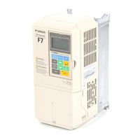
YASKAWA CIMR-F7Z Manuals
Manuals and User Guides for YASKAWA CIMR-F7Z. We have
2
YASKAWA CIMR-F7Z manuals available for free PDF download: Instruction Manual
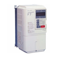
YASKAWA CIMR-F7Z Instruction Manual (374 pages)
Current Vector Controlled, General-Purpose Inverter
Brand:
YASKAWA
| Category:
Inverter
| Size: 6 MB
Table of Contents
Table of Contents
3
Warnings
11
Safety Precautions and Instructions for Use
12
EMC Compatibility
14
Schaffner Line Filters
16
Registered Trademarks
19
Handling Inverters
21
Varispeed F7 Introduction
22
Varispeed F7 Applications
22
Varispeed F7 Models
22
Confirmations Upon Delivery
24
Checks
24
Nameplate Information
24
Component Names
25
Exterior and Mounting Dimensions
28
Open Chassis Inverters (IP00)
28
Enclosed Wall-Mounted Inverters (NEMA1)
29
Checking and Controlling the Installation Site
31
Installation Site
31
Controlling the Ambient Temperature
31
Protecting the Inverter from Foreign Matter
31
Installation Orientation and Space
32
Removing and Attaching the Terminal Cover
33
Removing the Terminal Cover
33
Attaching the Terminal Cover
33
Removing/Attaching the Digital Operator and
34
Inverters of 18.5 Kw or Less
34
Inverters of 22 Kw or more
36
Wiring
39
Connections to Peripheral Devices
40
Connection Diagram
41
Circuit Descriptions
42
Terminal Block Configuration
43
Wiring Main Circuit Terminals
44
Applicable Wire Sizes and Closed-Loop Connectors
44
Main Circuit Terminal Functions
50
Main Circuit Configurations
51
Standard Connection Diagrams
52
Wiring the Main Circuits
53
Wiring Control Circuit Terminals
60
Wire Sizes
60
Control Circuit Terminal Functions
62
Control Circuit Terminal Connections
65
Control Circuit Wiring Precautions
66
Wiring Check
67
Checks
67
Installing and Wiring Option Cards
68
Option Card Models and Specifications
68
Installation
68
PG Speed Control Card Terminals and Specifications
70
Wiring
71
Wiring Terminal Blocks
73
Digital Operator and Modes
75
Digital Operator
76
Digital Operator Display
76
Digital Operator Keys
76
Modes
78
Inverter Modes
78
Switching Modes
79
Drive Mode
80
Quick Programming Mode
81
Advanced Programming Mode
82
Verify Mode
84
Autotuning Mode
85
Trial Operation
87
Trial Operation Procedure
88
Trial Operation
89
Application Confirmation
89
Setting the Power Supply Voltage Jumper (400 V Class Inverters of 75 Kw or Higher)
89
Power on
90
Checking the Display Status
90
Basic Settings
91
Settings for the Control Methods
93
Autotuning
94
Application Settings
99
No-Load Operation
99
Loaded Operation
100
Check and Recording Parameters
100
Adjustment Suggestions
102
User Parameters
105
User Parameter Descriptions
106
Description of User Parameter Tables
106
Digital Operation Display Functions and Levels
107
User Parameters Setable in Quick Programming Mode
108
User Parameter Tables
111
A: Setup Settings
111
Application Parameters: B
113
Tuning Parameters: C
122
Reference Parameters: D
128
Motor Parameters: E
133
Option Parameters: F
138
Terminal Function Parameters: H
142
Protection Function Parameters: L
151
N: Special Adjustments
159
Digital Operator Parameters: O
161
U: Monitor Parameters
165
Factory Settings that Change with the Control Method (A1-02)
172
Factory Settings that Change with the Inverter Capacity (O2-04)
174
Parameter Initial Values that Change with the Setting of C6-01
176
Parameter Setting Ranges that Change with the Setting of C6-01
177
Parameter Settings by Function
179
Application and Overload Selections
180
Select the Overload to Suit the Application
180
Frequency Reference
185
Selecting the Frequency Reference Source
185
Using Multi-Step Speed Operation
188
Run Command Input Methods
190
Selecting the Run Command Source
190
Stopping Methods
192
Selecting the Stopping Method When a Stop Command Is Input
192
Using the DC Injection Brake
195
Using an Emergency Stop
196
Acceleration and Deceleration Characteristics
197
Setting Acceleration and Deceleration Times
197
Accelerating and Decelerating Heavy Loads (Dwell Function)
200
Preventing the Motor from Stalling During Acceleration (Stall Prevention During Acceleration Function)
201
Preventing Overvoltage During Deceleration
202
Adjusting Frequency References
204
Adjusting Analog Frequency References
204
Operation Avoiding Resonance (Jump Frequency Function)
206
Adjusting Pulse Train Input Reference Values
207
Speed Limit (Frequency Reference Limits)
208
Limiting the Maximum Output Frequency
208
Limiting the Minimum Output Frequency
208
Frequency Detection
209
Speed Agreement Function
209
Improving the Operation Performance
211
Reducing the Motor Speed Fluctuation (Slip Compensation Function)
211
Torque Compensation for Sufficient Torque at Start and Low-Speed Operation
213
Automatic Speed Regulator (ASR) (for V/F with PG)
214
Hunting-Prevention Function
219
Stabilizing Speed (Automatic Frequency Regulator)
220
Machine Protection
221
Limiting Motor Torque (Torque Limit Function)
221
Preventing Motor Stalling During Operation
223
Motor Torque Detection
224
Motor Overload Protection
226
Motor Overheating Protection Using PTC Thermistor Inputs
228
Limiting Motor Rotation Direction and Output Phase Rotation
229
Automatic Restart
230
Restarting Automatically after Momentary Power Loss
230
Speed Search
231
Continuing Operation at Constant Speed When the Frequency Reference Is Lost
235
Restarting Operation after Transient Error (Auto Restart Function)
236
Inverter Protection
237
Overheating Protection for an Inverter-Mounted Braking Resistor
237
Inverter Overheat Protection
238
Input Open Phase Protection
238
Output Open Phase Protection
239
Ground Fault Protection
239
Cooling Fan Control
240
Setting the Ambient Temperature
240
OL2 Characteristics at Low Speed
241
Input Terminal Functions
242
Temporarily Switching Operation between Digital Operator and Control Circuit Terminals
242
Blocking Inverter Outputs (Baseblock Commands)
242
OH2 (Overheat) Alarm Signal Input
243
Multifunction Analog Input A2 Disable/Enable
243
Drive Enable/Disable
244
Stopping Acceleration and Deceleration (Acceleration/Deceleration Ramp Hold)
244
Raising and Lowering Frequency References Using Contact Signals (UP/DOWN)
246
Adding/Subtacting a Fixed Speed to an Analog Reference (Trim Control)
248
Hold Analog Frequency Using User-Set Timing
249
Switching Operation Source to Communication Option Card
250
Jog Frequency with Direction Commands (FJOG/RJOG)
250
Stopping the Inverter on External Device Errors (External Error Function)
251
Output Terminal Functions
252
Monitor Parameters
255
Using the Analog Monitor Outputs
255
Using the Pulse Train Monitor Output
256
Individual Functions
258
Using MEMOBUS Communications
258
Using the Timer Function
272
Using PID Control
273
Energy-Saving
283
Field Weakening
284
Field Forcing
285
Setting Motor 1 Parameters
285
Setting the V/F Pattern 1
287
Setting Motor 2 Parameters
293
Setting the V/F Pattern 2
294
Torque Control
295
Droop Control Function
301
Zero-Servo Function
302
Kinetic Energy Buffering
304
High Slip Braking (HSB)
305
Digital Operator Functions
307
Setting Digital Operator Functions
307
Copying Parameters
309
Prohibiting Overwriting of Parameters
313
Setting a Password
313
Displaying User-Set Parameters Only
314
Option Cards
315
Using PG Feedback Option Cards
315
Analog Reference Cards
318
Digital Reference Cards
318
Troubleshooting
323
Protective and Diagnostic Functions
324
Fault Detection
324
Alarm Detection
331
Operator Programming Errors
335
Auto-Tuning Fault
337
Digital Operator Copy Function Faults
338
Troubleshooting
340
If a Parameter Cannot be Set
340
If the Motor Does Not Operate Properly
341
If the Direction of the Motor Rotation Is Reversed
342
If the Motor Stalls or Acceleration Is Slow
342
If the Motor Operates at Higher Speed than the Frequency Reference
343
If There Is Low Speed Control Accuracy above Base Speed in Open Loop Vector Control Mode
343
If Motor Deceleration Is Slow
343
If the Motor Overheats
344
If Peripheral Devices Like Plcs or Others Are Influenced by the Starting or Running Inverter
344
If the Earth Leakage Breaker Operates When the Inverter Is Running
344
If There Is Mechanical Oscillation
345
If the Motor Rotates Even When Inverter Output Is Stopped
346
If Output Frequency Does Not Rise to Frequency Reference
346
Maintenance and Inspection
347
Maintenance and Inspection
348
Periodic Inspection
348
Periodic Maintenance of Parts
349
Cooling Fan Replacement
350
Removing and Mounting the Terminal Card
352
Specifications
353
Standard Inverter Specifications
354
Specifications by Model
354
Common Specifications
356
Appendix
359
Inverter Application Precautions
360
Selection
360
Installation
361
Settings
361
Handling
362
Motor Application Precautions
363
Using the Inverter for an Existing Standard Motor
363
Using the Inverter for Special Motors
364
Power Transmission Mechanism (Speed Reducers, Belts and Chains)
364
User Constants
365
Advertisement
YASKAWA CIMR-F7Z Instruction Manual (67 pages)
Brand:
YASKAWA
| Category:
DC Drives
| Size: 0 MB
Table of Contents
Table of Contents
2
General Specifications
4
Specification Sheet
4
Connection Diagram
5
Changes with the Standard F7Z Drive
6
Test Run
35
Description of Additional Functions
36
Faults and Counter-Measures (for New and Modified Faults)
52
Appendix-1: How Parameters Are Calculated
53
Appendix-2: Check Point
58
Appendix-3: Tuning Procedure
60
Appendix-4: Parameter Tables
62
Advertisement
Related Products
YASKAWA CIMR-F7U23P7
YASKAWA CIMR-F7U25P5
YASKAWA CIMR-F7U2011
YASKAWA CIMR-F7U2022
YASKAWA CIMR-F7U2030
YASKAWA CIMR-F7U2090
YASKAWA CIMR-F7U42P2
YASKAWA CIMR-F7U44P0
YASKAWA CIMR-F7U4011
YASKAWA CIMR-F7Z44P0
YASKAWA Categories
Controller
DC Drives
Servo Drives
Robotics
Control Unit
More YASKAWA Manuals
Login
Sign In
OR
Sign in with Facebook
Sign in with Google
Upload manual
Upload from disk
Upload from URL