SMC Networks HECR Series Manual
Peltier-type chiller thermo-con/ rack mount type
Hide thumbs
Also See for HECR Series:
- Installation and maintenance manual (4 pages) ,
- Manual (16 pages) ,
- Communications manual (42 pages)
Table of Contents
Advertisement
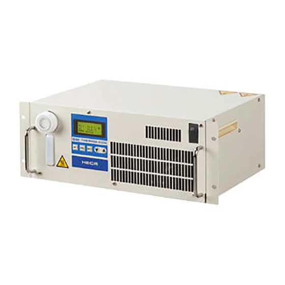
Peltier-Type Chiller
Thermo-con/
Rack Mount Type
Good space utilisation
Mountable in a 19-inch rack
Saves space by mounting multiple equipment
together in a rack.
Temperature stability
0.01
±
°C to
Set temperature range
10
60
°C to
Cooling capacity
New
New
200
,
400
W
800
, 1
W
kW
HECR
Series
Space saving design with reduced height
0.03
°C
°C
New
New
,
510
W
Air-cooled
176
mm
HECR002 (200 W)
HECR004 (400 W)
New
New
HECR006 (510 W)
Energy saving design
Power consumption
200
,
W
(HECR004/006)
400
(HECR008/010)
New
New
HECR008 (800 W)
HECR010 (1 kW)
Low-noise design
Noise level
55
W
dB
∗1
(HECR004/006)
54
W
dB
∗2
(HECR008/010)
∗1: 200 W load ∗2: 500 W load
CAT.EUS40-61C-UK
(UL Standards)
RoHS
267
mm
∗1
∗2
Advertisement
Table of Contents

Subscribe to Our Youtube Channel
Related Manuals for SMC Networks HECR Series


Summary of Contents for SMC Networks HECR Series
- Page 1 Peltier-Type Chiller Thermo-con/ Rack Mount Type (UL Standards) Air-cooled RoHS Good space utilisation Mountable in a 19-inch rack Saves space by mounting multiple equipment together in a rack. Temperature stability Space saving design with reduced height 0.01 0.03 ± °C to °C Set temperature range HECR002 (200 W)
- Page 2 Peltier-Type Chiller Thermo-con/Rack Mount Type HECR Series Can precisely control the temperature of a heat source or process fluid. Precisely control the temperature of the circulating fluid by using the Peltier device. Refrigerant-free and environmentally friendly. Learning control function (Temperature control by external temperature sensor) This function adjusts the fl...
- Page 3 Peltier-Type Chiller Thermo-con/Rack Mount Type HECR Series Construction and Principles Figure 1 Power switch Controller Power supply & Controller Switching power supply (DC power supply) Flow switch (Option) Heat exchanger Circulating fluid (Circulating fluid side) Peltier device Temperature Circulating fluid supply port sensor (Thermo-module) (Tank lid)
- Page 4 Peltier-Type Chiller Thermo-con/Rack Mount Type HECR Series Application Examples Laser machining UV curing device (printing, painting, bonding and sealing) Cooling of laser irradiated part Cooling of UV lamp X-ray instrument Electronic microscope (digital) Temperature control of X-ray tube and Temperature control X-ray light sensing part of electron-beam irradiated part...
-
Page 5: Table Of Contents
C O N T E N T S HECR Series Thermo-con/Rack Mount Type HECR Series Model Selection ................Page 5 ........Page 7 Air-cooled How to Order/Specifications Cooling Capacity ................. Page 8 Heating Capacity ................ Page 10 Pump Capacity (Thermo-con Outlet) .......... Page 12 Dimensions ................. -
Page 6: Model Selection
HECR Series Model Selection Guide to Model Selection 1. How much is the temperature in degrees centigrade for the circulating fl uid? Temperature range which can be set with the thermo-con: 10 to 60 °C If a lower temperature (down to –20 °C) or higher temperature (up to 90 °C) than this range is necessary, select the thermo-chiller HRZ series. - Page 7 HECR Series Model Selection Guide to Model Selection Example 2 When the heat generation amount in the user’s equipment is not known. Obtain the temperature difference between inlet and outlet by circulating the fluid inside the user’s equipment. Heat generation amount Q : Unknown Circulating fluid temperature difference ΔT (= T2 –...
-
Page 8: How To Order/Specifications Air-Cooled
Thermo-con/ Rack Mount Type (UL Standards) HECR Air-cooled Series How to Order HECR 002 Cooling capacity Option — 200 W None 400 W With feet and no rack mounting brackets 510 W With fl ow switch 800 W High pressure pump mounted 1 kW ¡... -
Page 9: Cooling Capacity
HECR Series Thermo-con/Rack Mount Type Cooling Capacity HECR002 Circulating fluid: Tap water Circulating fluid: Ethylene glycol 20 % Ambient temperature 15 °C Ambient Ambient temperature 25 °C temperature 25 °C Ambient temperature 35 °C Circulating fluid temperature [°C] Circulating fluid temperature [°C] HECR004 Circulating fluid: Tap water Circulating fluid: Ethylene glycol 20 %... - Page 10 HECR Series Cooling Capacity HECR008 Circulating fluid: Tap water Circulating fluid: Ethylene glycol 20 % 2500 2500 Ambient temperature 15 °C 2000 2000 1500 1500 Ambient temperature 25 °C Ambient 1000 1000 temperature 25 °C Ambient temperature 35 °C Circulating fluid temperature [°C] Circulating fluid temperature [°C] HECR010 Circulating fluid: Tap water...
-
Page 11: Heating Capacity
HECR Series Thermo-con/Rack Mount Type Heating Capacity HECR002 Circulating fluid: Tap water Circulating fluid: Ethylene glycol 20 % 1000 1000 Ambient temperature 35 °C Ambient temperature 25 °C Ambient temperature 25 °C Ambient temperature 15 °C Circulating fluid temperature [°C] Circulating fluid temperature [°C] HECR004 Circulating fluid: Tap water... - Page 12 HECR Series Heating Capacity HECR008 Circulating fluid: Tap water Circulating fluid: Ethylene glycol 20 % 2500 2500 2000 2000 Ambient temperature 35 °C 1500 1500 Ambient temperature 25 °C Ambient temperature 25 °C 1000 1000 Ambient temperature 15 °C Circulating fluid temperature [°C] Circulating fluid temperature [°C] HECR010 Circulating fluid: Tap water...
-
Page 13: Pump Capacity (Thermo-Con Outlet)
HECR Series Thermo-con/Rack Mount Type Pump Capacity (Thermo-con Outlet) HECR002 When high-pressure pump mounted 0.10 0.14 0.12 Tap water 0.08 Tap water 0.10 0.06 0.08 Ethylene glycol 20 % Ethylene glycol 20 % 0.06 0.04 0.04 0.02 0.02 0.00 Circulating fluid flow rate [l/min] Circulating fluid flow rate [l/min] HECR004 When high-pressure pump mounted... - Page 14 HECR Series Pump Capacity (Thermo-con Outlet) HECR008,010 When high-pressure pump mounted 0.18 0.35 0.16 0.14 Tap water Tap water 0.25 0.12 Ethylene glycol 20 % Ethylene glycol 20 % 0.08 0.15 0.06 0.04 0.05 0.02 Circulating fluid flow rate [l/min] Circulating fluid flow rate [l/min]...
-
Page 15: Dimensions
HECR Series Thermo-con/Rack Mount Type Dimensions HECR002-A5 Communication connector Ventilation hole (air outlet) Label External temperature sensor connector Power supply connector Alarm output connector Model no. label Circulating fluid inlet Ventilation hole (air outlet) Circulating fluid outlet (Circulating fluid drain port) Rc 1/4 Rc 1/4 Ventilation hole (air inlet) - Page 16 HECR Series Dimensions HECR004-A5 Ventilation hole (air outlet) Communication connector Power supply connector External temperature sensor connector Alarm output connector Model no. label Label Circulating fluid inlet (Circulating fluid drain port) Ventilation hole (air outlet) Circulating fluid outlet Rc 3/8 Rc 3/8 Ventilation hole (air inlet) Display/Operation panel...
- Page 17 HECR Series Thermo-con/Rack Mount Type Dimensions HECR006-A5 Ventilation hole (air outlet) Communication connector Power supply connector External temperature sensor connector Alarm output connector Model no. label Label Circulating fluid inlet (Circulating fluid drain port) Ventilation hole (air outlet) Circulating fluid outlet Rc 3/8 Rc 3/8 Ventilation hole (air inlet)
- Page 18 HECR Series Dimensions Ventilation hole (air outlet) Model no. label External temperature sensor connector HECR008-A5 Alarm output connector Label HECR010-A2 Communication connector Power supply connector Circulating fluid inlet Circulating fluid outlet Rc 3/8 Rc 3/8 Ventilation hole (air inlet) Display/ Tank lid (with gasket) Circulating fluid level gauge Operation panel...
-
Page 19: Operation Display Panel
HECR Series Thermo-con/Rack Mount Type Operation Display Panel 1st line 2nd, 3rd line Indicates No. corresponding to the alarm Indicates present temperature [PV] and E R R 1 1 W R N which arises and [WRN] comes to light < target temperature [SV] during normal 3 1 . -
Page 20: Options
HECR Series Note) Options have to be selected when Options ordering the thermo-con. It is not possible to add them after purchasing the unit. Option symbol With Feet and No Rack Mounting Brackets HECR With feet and no rack mounting brackets Rack mounting brackets and handles on the front side are removed as they are not necessary when the product is not mounted in a rack. -
Page 21: Optional Accessories
HECR Series Optional Accessories The power supply cable can only be used for the applicable models shown below. Do not use it for other products. q Power Supply Cable í For single-phase 100/115 V AC type ∗ Not applicable for the 200 V type. Approx. -
Page 22: Specific Product Precautions 1
HECR Series Specific Product Precautions 1 Be sure to read this before handling. Refer to the back cover for Safety Instructions. For Temperature Control Equipment Precautions, refer to “Handling Precautions for SMC Products” and the Operation Manual on the SMC website, http://www.smc.eu System Design Radiation Air Warning... - Page 23 HECR Series Specific Product Precautions 2 Be sure to read this before handling. Refer to the back cover for Safety Instructions. For Temperature Control Equipment Precautions, refer to “Handling Precautions for SMC Products” and the Operation Manual on the SMC website, http://www.smc.eu Circulating Fluid Circulating Fluid Caution...
- Page 24 These safety instructions are intended to prevent hazardous situations and/or Safety Instructions equipment damage. These instructions indicate the level of potential hazard with the labels of “Caution,” “Warning” or “Danger.” They are all important notes for safety ∗1) and must be followed in addition to International Standards (ISO/IEC) , and other safety regulations.
Need help?
Do you have a question about the HECR Series and is the answer not in the manual?
Questions and answers
Hello I have chiller model HECR008-A5 and I am having trouble draining the chiller coolant to replace it. I would like step by step instructions. I used a hose that clicked into the draining value but still, not draining. Also, how often should this process be done (once a year?)
To drain the coolant from the SMC Networks HECR008-A5 chiller, use the circulating fluid outlet, which also functions as the circulating fluid drain port. It is labeled and uses an Rc 1/4 connection.
Maintenance, including checking fluid level and draining if necessary, should be performed at least once a month by a knowledgeable operator.
This answer is automatically generated