Sign In
Upload
Download
Table of Contents
Contents
Add to my manuals
Delete from my manuals
Share
URL of this page:
HTML Link:
Bookmark this page
Add
Manual will be automatically added to "My Manuals"
Print this page
×
Bookmark added
×
Added to my manuals
Manuals
Brands
Edwards Manuals
Water Pump
HV30000
Instruction manual
Edwards HV30000 Instruction Manual
Vacuum booster pump
Hide thumbs
1
2
Table Of Contents
3
4
5
6
7
8
9
10
11
12
13
14
15
16
17
18
19
20
21
22
23
24
25
26
27
28
29
30
31
32
33
34
35
36
37
38
39
40
41
42
43
44
page
of
44
Go
/
44
Contents
Table of Contents
Bookmarks
Table of Contents
Table of Contents
Introduction
Scope and Definitions
Description
Principle of Operation
Operating Principles
Components of the HV Pump
Application
Normal Operation
Abnormal Operation
Technical Data
Operating and Storage Conditions
Critical Backing Pressure
Performance
Performance Data: Safe Area HV Pumps
Cooling-Water Supply
Mechanical Data
Lubrication Data
Cooling-Water Supply Data
Electrical Data
Connections
Noise and Vibration Data
Connections Data
Materials of Construction
Item Numbers
Construction Materials Data
HV Dimensions: MM (Inch)
Installation
Installation Safety
System Requirements
Unpack and Inspect
Locate the Pump
Checklist of Items
Fill the Pump with Oil
Fill the Drive End Cover
Fill the Non-Drive End Cover
Fill the Shaft-Seals Oil Reservoir
Connect the Cooling-Water Pipelines
Fit the Drive/Transmission (Bareshaft HV Pumps Only)
Fitting the Bell-Housing, Coupling and Motor
Motor Electrical Connections
Introduction
Connect the Electrical Supply
Connect the Motor Thermistors (if Fitted)
Connect the Motor Thermostats (if Fitted)
Earth (Ground) Connection
Example Electrical Control Circuit
Check the Direction of Rotation
Inlet/Outlet Flange Loading Limits (Nm)
Connect the Pump-Inlet and Outlet
Commission the HV Pump
Operation
Operational Safety
Start-Up
Pre-Start Checks
Shut-Down
Maintenance
Safety Information
Maintenance Plan
Check the Shaft-Seals Reservoir Oil-Level
Inspect the Oil-Level Sight-Glasses
Check the End Cover Oil Level
Drive End Cover
Non-Drive End Cover
Inspect the System Installation
Change the Oil
Drive End Cover
Non-Drive End Cover
Overhaul the Pump
Fault Finding
Fault Finding
Storage and Disposal
Storage
Preparation
Long-Term Storage
Disposal
Service and Spares
Introduction
Service
Spares
Advertisement
Quick Links
1
Scope and Definitions
2
Description
3
Technical Data
4
Spares
Download this manual
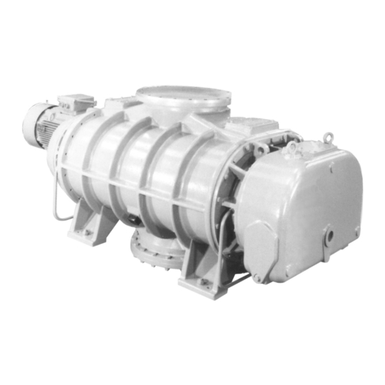
HV30000 and HV40000 Vacuum Booster Pump
Description
HV30000 Vertical Flow Vacuum Booster Pump
HV40000 Vertical Flow Vacuum Booster Pump
Instruction Manual
A313-01-880
Issue A Original
Item Number
A313-01-985
A314-01-985
Table of
Contents
Previous
Page
Next
Page
1
2
3
4
5
Advertisement
Table of Contents
Need help?
Do you have a question about the HV30000 and is the answer not in the manual?
Ask a question
Questions and answers
Related Manuals for Edwards HV30000
Water Pump Edwards HV8000 VF Instruction Manual
Booster pumps (50 pages)
Water Pump Edwards HV8000 HF Instruction Manual
Booster pumps (50 pages)
Water Pump Edwards HT10 Instruction Manual
High throughput diffusion pumps (56 pages)
Water Pump Edwards HV40000 Instruction Manual
Vacuum booster pump (44 pages)
Water Pump Edwards STP Series Instruction Manual
Stp series turbomolecular pumps (59 pages)
Water Pump Edwards E2M0.7 Instruction Manual
Rotary vacuum pumps (38 pages)
Water Pump Edwards RV3 Instruction Manual
Rotary vane pumps (58 pages)
Water Pump Edwards STP-301 Series Instruction Manual
Stp series turbomolecular pumps (121 pages)
Water Pump Edwards EH500 Instruction Manual
(15 pages)
Water Pump Edwards XDS 5 Instruction Manual
Xds dry pump (42 pages)
Water Pump Edwards nEXT200200 Instruction Manual
Mechanical turbomolecular pumps (100 pages)
Water Pump Edwards nES Series Instruction Manual
Stage rotary vane pumps (56 pages)
Water Pump Edwards iXH100 Instruction Manual
Dry pumping systems (88 pages)
Water Pump Edwards RV3 Instruction Manual
Rotary vane pumps (64 pages)
Water Pump Edwards E2M28 Instruction Manual
Rotary vacuum pumps (48 pages)
Water Pump Edwards STP-iS2207 Series Instruction Manual
Turbomolecular pump (165 pages)
This manual is also suitable for:
Hv40000
A313-01-985
A314-01-985
Table of Contents
Print
Rename the bookmark
Delete bookmark?
Delete from my manuals?
Login
Sign In
OR
Sign in with Facebook
Sign in with Google
Upload manual
Upload from disk
Upload from URL


Need help?
Do you have a question about the HV30000 and is the answer not in the manual?
Questions and answers