Table of Contents
Advertisement
Quick Links
Description
HV8000 VF 400 V 50 Hz 230/460 V 60 Hz 18.5 kW BOOSTER
HV8000 VF 200 V 50 Hz 200/380 V 60 Hz 18.5 kW BOOSTER
HV8000 VF BARESHAFT BOOSTER
HV8000 HF 380/400 V 50 Hz 230/460 V 60 Hz 18.5 kW BOOSTER
HV8000 HF 200 V 50 Hz 200/380 V 60 Hz 18.5 kW BOOSTER
HV8000 HF BARESHAFT BOOSTER
Instruction Manual
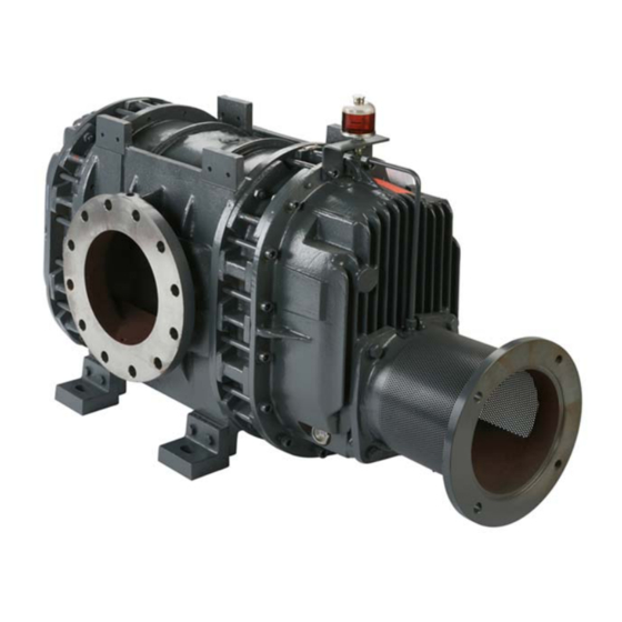
HV8000 Booster Pumps
A311-03-880
Issue A
Original Instructions
Item Number
A311-03-940
A311-03-934
A311-01-985
A311-04-940
A311-04-934
A311-02-985
Advertisement
Table of Contents


Need help?
Do you have a question about the HV8000 VF and is the answer not in the manual?
Questions and answers