Table of Contents
Advertisement
Available languages
Available languages
Quick Links
Advertisement
Table of Contents

Related Manuals for Cebora PGC-H2


Summary of Contents for Cebora PGC-H2
- Page 1 MANUALE DI ISTRUZIONE PER IMPIANTO DI TAGLIO AL PLASMA PAG. 4 EN INSTRUCTION MANUAL FOR PLASMA CUTTING SYSTEM PAGE 11 Parti di ricambio e schema elettrico Spare parts and electrical schematics ÷ Pagg. Sid. 3301092 08/07/2020...
- Page 2 Tel. +39.051.765.000 - Fax. +39.051.765.222 www.cebora.it - e-mail: cebora@cebora.it L'USO DI CONSUMABILI NON ORIGINALI CEBORA FA AUTOMATICAMENTE DECADERE OGNI GARANZIA E/O RESPONSABILITÀ SU GENERATORI E TORCE PER IL TAGLIO AL PLASMA. THE USE OF NON-GENUINE CEBORA CONSUMABLES AUTOMATICALLY VOIDS ANY WARRANTY AND/OR RESPONSIBILITY ON PLASMA CUTTING POWER SOURCES AND TORCHES DIE GARANTIE UND/ODER HAFTUNG FÜR DIE STROMQUELLEN UND BRENNER ZUM...
-
Page 3: Table Of Contents
Dell impianto pgc-H2 -a .487 ..........................6 as console INSTALLAZIONE ..............................7 ............................7 isimballo e assemblaggio pgc-H2 ....................... 7 ollegamento Della gas console IMPIEGO ................................8 pgc-H2 - .487 ................8 escrizione Del pannello Della as console pgc-H2 pgc-D ........... -
Page 4: Precauzioni Di Sicurezza
MANUALE DI ISTRUZIONE PER IMPIANTO DI TAGLIO AL PLASMA IMPORTANTE: PRIMA DELLA MESSA IN OPERA DEL- L’APPARECCHIO LEGGERE IL CONTENUTO DI QUESTO MA- NUALE E CONSERVARLO, PER TUTTA LA VITA OPERATIVA, IN UN LUOGO NOTO AGLI INTERESSATI. QUESTO APPARECCHIO DEVE ESSERE UTILIZZATO ESCLUSIVAMENTE PER OPERAZIONI DI SALDATURA. PRECAUZIONI DI SICUREZZA LA SALDATURA ED IL TAGLIO AD ARCO POSSONO ESSERE NOCIVI PER VOI E PER GLI ALTRI, pertan- to l’utilizzatore deve essere istruito contro i rischi, di seguito riassunti, derivanti dalle operazioni di salda-... - Page 5 1.1 TARGA DELLE AVVERTENZE Il testo numerato seguente corrisponde alle caselle numerate della targa. Le scintille provocate dal taglio possono causare esplosioni od incendi. 1.1 Tenere i materiali infiammabili lontano dall’area di taglio. 1.2 Le scintille provocate dal taglio possono causare incendi. Tenere un estintore nelle immediate vicinanze e far sì che una persona resti pronta ad utilizzarlo.
-
Page 6: Dati Tecnici
DATI TECNICI Descrizione generale dell’impianto La gas console PGC-H2 è un dispositivo opzionale che può essere aggiunto ad un impianto HQC con generatori art.968. Gas console PGC-H2 -Art.487 La gas console PGC-H2 è un dispositivo accessorio atto a gestire i flussi delle miscele H35 (35% idrogeno H2 – 65% argon Ar) ed F5 (5% idrogeno H2 – 95% azoto N2) necessari per i tagli di Stainless Steel e Alluminio di qualità elevata. In particolare, è adatta al taglio dello Stainless Steel di spessori medio-alti. -
Page 7: Installazione
Seguire scrupolosamente lo schema di messa a terra evidenziato in Appendice. Disimballo e assemblaggio Fissare la gas console PGC-H2 alla parte inferiore della gas console PGC-D, seguendo i passaggi di seguito eviden- ziati. 1. Svitare i piedi della gas console, appoggiare la piastra di collegamento sul fondo della stessa e riavvitare i piedi 2. -
Page 8: Impiego
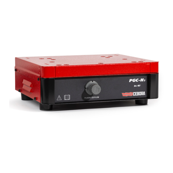
Tutte le funzioni dell’impianto si gestiscono tramite il pannello della gas console PGC-D art.480. Il pannello anteriore della gas console PGC-H2 presenta un riduttore di pressione con il quale è possibile regolare la pressione di PLASMA CUTFLOW qualora si scelga la combinazione di taglio H35/N2 oppure F5/N2. -
Page 9: Qualità Del Taglio
Sostituire gli O-ring della torcia, ordinando il kit art.1400 Se, in seguito ad un controllo, si nota un componente eccessivamente usurato o un suo funzionamento non regolare, contattare il Servizio Assistenza CEBORA. Per una manutenzione delle parti interne dei diversi componenti l’impianto, richiedere l’intervento di personale qualifi- cato. In particolare, si consiglia di eseguire periodicamente le operazioni di seguito elencate. - Page 10 Per ogni componente: Componente Operazioni di manutenzione Generatore Pulire con aria compressa i radiatori dei moduli IGBT, dirigendo il getto d’aria su di essi . Gruppo di Pulire con aria compressa il radiatore, dirigendo il getto d’aria su di esso. raffredda- Controllare il circuito idraulico interno riguardo a screpolature o perdite.
- Page 11 ........................14 eneral Description of tHe eQuipment pgc-H2-a . 487 ..........................14 as console INSTALLATION ��������������������������������������������������������������������������������������������������������������������������������������������������� 15 ............................15 npacking anD assembly pgc-H2 ........................15 onnecting tHe onsole USE ���������������������������������������������������������������������������������������������������������������������������������������������������������������������� 16 pgc-H2 - .487 ....................16 as console panel Description...
- Page 12 INSTRUCTION MANUAL FOR PLASMA CUTTING SYSTEM IMPORTANT: BEFORE STARTING THE EQUIPMENT, READ THE CONTENTS OF THIS MANUAL, WHICH MUST BE STORED IN A PLACE FAMILIAR TO ALL USERS FOR THE ENTIRE OPERATIVE LIFE-SPAN OF THE MACHINE. THIS EQUIPMENT MUST BE USED SOLELY FOR WELDING OPERATIONS. SAFETY PRECAUTIONS WELDING AND ARC CUTTING CAN BE HARMFUL TO YOURSELF AND OTHERS.
- Page 13 1�1 Warning label The following numbered text corresponds to the label numbered boxes. Cutting sparks can cause explosion or fire. 1.1 Keep flammable materials away from cutting. 1.2 Cutting sparks can cause fires. Have a fire extinguisher nearby, and have a watchperson ready to use it. 1.3 Do not cut on drums or any closed container.
- Page 14 It contains solenoid valves, pressure reducers and transducers which are powered by the PGC-D gas console. The PGC-H2 gas console is fed by the mixtures H35 (35% hydrogen H2 - 65% argon Ar) and F5 (5% hydrogen H2 - 95% nitrogen N2) at a maximum pressure of 0.8 MPa (8 bar) as indicated in the table below .
- Page 15 1. Unscrew the feet of the gas console, place the connection plate on the bottom of the console and screw the feet back on. 2. Fix the connection plate to the gas console PGC-H2 using the dedicated fixing screws (2 in the rear and 2 in the front) 3�2...
- Page 16 All system functions are managed via the gas panel PGC-D console art.480. The front panel of the PGC-H2 gas console features a pressure reducer with which it is possible to adjust the pressure of PLASMA CUTFLOW if you choose the combination of cutting H35 / N2 or F5 / N2.
- Page 17 Replace the torch O-rings, and order the kit art.1400 If, during an inspection, a highly worn component part is found or one that is not working properly, contact the CEBORA assistance service. To service the inner parts of the different system components, request the assistance of qualified personnel. In particu- lar, the following operations are best performed periodically.
- Page 18 For all the component parts: • Clean the inside with compressed air (clean, dry and oil free) to eliminate any dust build up. If possible use a vacuum cleaner; • Make sure the power connections are tight and are not overheating. For each component part: Component Maintenance operations...
- Page 19 Schemi elettrici e Parti di ricambio Electrical schematics and Spare parts Schaltplan und Ersatzteile Schémas électrique et Pièces détachées Esquemas eléctricos y Partes de repuesto Esquema eléctricos e Partes sobressalentes Sähkökaavio ja Varaosat 19/24...
- Page 20 CODIFICA COLORI WIRING DIAGRAM CODIFICA COLORI WIRING DIAGRAM CABLAGGIO ELETTRICO COLOUR CODE CABLAGGIO ELETTRICO COLOUR CODE NERO BLACK ROSA-NERO PINK-BLACK ROSSO GRIGIO-VIOLA GREY-PURPLE GRIGIO GREY BIANCO-VIOLA WHITE-PURPLE BIANCO WHITE BIANCO-NERO WHITE-BLACK VERDE GREEN GRIGIO-BLU GREY-BLUE VIOLA PURPLE BIANCO-ROSSO WHITE-RED GIALLO YELLOW GRIGIO-ROSSO GREY-RED...
- Page 21 Art. 487 21/24...
- Page 22 Art. 487 22/24...
- Page 23 Art. 487 POS DESCRIZIONE DESCRIPTION POS DESCRIZIONE DESCRIPTION FASCIONE HOUSING RACCORDO FITTING FONDO+PANNELLO BOTTOM RACCORDO FITTING PANNELLO ANTERIORE FRONT PANEL CONNESSIONE TRASDUT- TRANSDUCERS TORE CONNECTOR PIEDE IN GOMMA RUBBER FOOT CONNESSIONE CON CON- PRESSURE REDUCER CONNECTOR GRUPPO RIDUTTORE NETTORE UNIT MOTOVENTOLA MOTOR WITH FAN GRUPPO SENSORE...
- Page 24 CEBORA S.p.A - Via Andrea Costa, 24 - 40057 Cadriano di Granarolo - BOLOGNA - Italy Tel. +39.051.765.000 - Fax. +39.051.765.222 www.cebora.it - e-mail: cebora@cebora.it...
Need help?
Do you have a question about the PGC-H2 and is the answer not in the manual?
Questions and answers