Advertisement
Quick Links
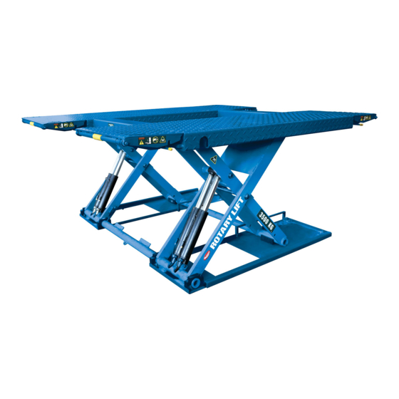
DS35 & DS35EX
© February 2016 by Vehicle Service Group. All rights reserved. CO9420.9
(000 Series)
Capacity 3,500 kg (7,700 lbs)
(Maximum 1,750 kg (3,850 lbs) per pad)
Read entire manual before assembling, installing,
operating, or servicing this equipment.
Intended for unibody vehicles and
some frame vehicles within the rated
lift capacity.
LP20633
Scissor Lift
Rev.B 9/2/2016
I
I
N
N
S
S
T
T
A
A
L
L
L
L
A
A
T
T
I
I
O
O
N
N
I
I
N
N
S
S
T
T
R
R
U
U
C
C
T
T
I
I
O
O
N
N
S
S
IN20754
Advertisement

Subscribe to Our Youtube Channel
Related Manuals for Rotary 000 Series


Summary of Contents for Rotary 000 Series
- Page 1 DS35 & DS35EX Scissor Lift (000 Series) Capacity 3,500 kg (7,700 lbs) (Maximum 1,750 kg (3,850 lbs) per pad) Read entire manual before assembling, installing, operating, or servicing this equipment. Intended for unibody vehicles and some frame vehicles within the rated lift capacity.
- Page 2 1. General Lift Location Use architects plan when available to locate lift. Fig. 1 and Fig. 1a shows typical lift dimensions. Control cabinet may be placed on the left or right. This is shown in Fig. 3. DS35 Scissor Lift 1500 Fig.
- Page 3 DS35EX Scissor Lift Fig. 1a 1500 *NOTE: 750mm WILL ACCOMMODATE MOST VEHICLES. LIFT MAY BE ADJUSTED DURING INSTALLATION BUT DISTANCE BETWEEN PLATFORMS SHOULD NOT EXCEED 912mm. SPECIFICATION SURFACE MOUNT FLUSH MOUNT COLLAPSED HEIGHT RAISED HEIGHT 1940 1835 *750 /900( 900 For BMW) 2010/2160 OVERALL LENGTH 2358...
- Page 4 2. Vertical Clearance IMPORTANT Never operate the motor on line voltage less than 208V. Motor damage may occur. Check the height of the area where the lift is to be installed. Clearance should be calculated based on the IMPORTANT Use separate circuit for each power unit. full raised height of the lift and the height of the tallest Protect each circuit with a time delay fuse or circuit vehicle being lifted.
- Page 5 SAFETY WARNING LABELS FOR HINGED FRAME ENGAGING LIFTS Lift Owner/User Responsibilities: A. This Safety Warning placard C. These Safety Warning labels SHALL be displayed in a supplement other documents conspicuous location in the lift area. supplied with the lift. B. Use one of the mounting D.
- Page 6 6. Installation 8. Flush Mount Pit Requirements Important: Prior to pouring concrete, installer will need either the Always wear safety glasses while installing lift. Full Flush Mount Kit (part # XX100003) or Recess Box Flush Mount Kit (part # XX100014). Please contact the Required Tools and Supplies List 1.
- Page 7 RECESS NYLON WELDMENT ANCHOR RECESS PUSH RECESS BOX TIGHT AGAINST CONCRETE WALL NYLON ANCHOR Fig. 2a RECESS PUSH RECESS BOX TIGHT AGAINST CONCRETE WALL NYLON ANCHOR M8 BOLT Fig. 2b RECESS HOSE COVER...
- Page 8 DS35 Flush Mount Only ROUTE CONDUIT TOWARDS THE CLOSEST DIRECTION OF CABINET PLACEMENT. EXITING EITHER THE SIDE OR BACK OF THE PIT IS ACCEPTABLE. 3660 MIN. TO 3660 MIN. TO NEAREST OBSTRUCTION NEAREST OBSTRUCTION 1675 TO NEAREST PIT WIDTH OBSTRUCTION DIRECTION OF APPROACH BETWEEN PITS...
- Page 9 DS35EX Flush Mount Only ROUTE CONDUIT TOWARDS THE CLOSEST DIRECTION OF CABINET PLACEMENT. EXITING EITHER THE SIDE OR BACK OF THE PIT IS ACCEPTABLE. 3660 MIN. TO 3660 MIN. TO NEAREST OBSTRUCTION NEAREST OBSTRUCTION 1675 TO NEAREST PIT WIDTH OBSTRUCTION DIRECTION OF APPROACH 843(BMW) / 69 3...
- Page 10 2000mm. should be in a position to notice any misalignment of lifting pads or vehicle during operation. Rotary Lift does not recommend placing the control cabinet in a different location orientation and doing so would be the responsibility of the installer and/or end user.
- Page 11 10. Control Cabinet Connections Use seperate circuit for each power IMPORTANT unit. Protect each circuit with a time delay fuse or Electrical Connection: circuit breaker. Use a 10 amp. (three phase) or 30 amp. Have a certified electrician run appropriate power (single phase) fuse.
- Page 12 Connect Main Power To Switch 3Ø 1Ø...
- Page 13 Connect One Platform Top Limit Switch and Stop Down Switch Fig. 4 Connect One Platform Top Limit Switch Fig. 5...
- Page 15 3. Push the “UP” button until both platforms stop 11. Oil Filling and Bleeding moving. Use Dexron III ATF, or hydraulic fluid that meets ISO32 specifications. Remove fill breather cap and add (10) 4. Add 5 liters more of fluid. ten quarts of fluid.
-
Page 16: Hydraulic Schematics
Hydraulic Schematics Fig. 7... - Page 17 12. Hydraulic Hose Routing 1.The control cabinet includes three removable covers for hydraulic routing, Fig.7a. 2. Customer to route hydraulic hose from lift to control cabinet panel as desired. See Fig. 7, and Fig. 7a. COVER COVER Fig. 7a COVER Fig.
- Page 18 4. Verify both platform bases are level front to rear, Fig. 13. Final Positioning of Platforms 1. Verify the platform bases are square and the distance between the platforms is correct. 5. Verify platforms are level, Fig. 9. 2. Verify platform bases are level, Fig. 8. 6.
- Page 19 Fig. 9a Fig. 9b 14. Anchoring 4. Shim as necessary, Fig. 9c, and tighten anchors. 1. Turn the disconnect switch to “ON” and press the 5. Grout if necessary. “UP” button to raise the platforms which provides room under the runways for drilling. 6.
- Page 20 Drill holes using 1/2” car- Clean hole. Run nut down just Tighten nut with bide tipped masonry drill below impact section Torque wrench to bit per ANSI B212.15-1994 of bolt. Drive anchor 40 ft.-lbs (54N-m) (R2000) into hole until nut and washer contact base.
- Page 21 16. Hose Covers and Anchoring Position hose covers as necessary per control cabinet location. Use provided anchors to fasten all hose covers securely, Fig. 10. Position hose covers directly under each platform to 1/2” clearance, Fig. 10a. NYLON ANCHORS Fig. 10 13mm CLEARANCE Fig.
- Page 22 3. Once the cushion screws are adjusted properly, 17. Adjust Cushion Device tighten lock nuts (48), Fig. 11. 1. To adjust platform height in down position, use cushion screws (49), Fig. 11. 4. Raise and lower lift once more to ensure screws are adjusted correctly.
- Page 23 18. Brand Decals Apply brand decals as shown, Fig. 12 and Fig. 12a. BRAND DECAL LOCATION (BOTH PLATFORMS OUTSIDE SCISSOR) Fig. 12 BRAND DECAL LOCATION (BOTH SIDES OF CABINET) Fig. 12a...
Need help?
Do you have a question about the 000 Series and is the answer not in the manual?
Questions and answers