Advertisement
Quick Links
© May 2010 by Rotary Lift. All rights reserved. CO7585.1
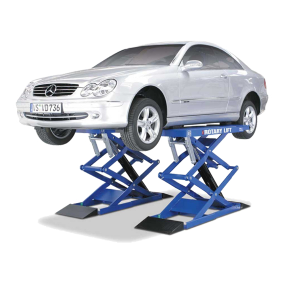
RLP35
Scissor Lift
(300 Series)
Capacity 7700 lbs (3500 kg)
(Maximum 3,850 lbs (1750 kg) per pad)
LP20469
I
I
N
N
S
S
T
T
A
A
L
L
L
L
A
A
T
T
I
I
O
O
N
N
I
I
N
N
S
S
T
T
R
R
U
U
C
C
T
T
I
I
O
O
N
N
S
S
IN20526
Rev. D 5/5/2010
Advertisement

Related Manuals for Rotary 300 Series


Summary of Contents for Rotary 300 Series
- Page 1 RLP35 Scissor Lift (300 Series) Capacity 7700 lbs (3500 kg) (Maximum 3,850 lbs (1750 kg) per pad) LP20469 IN20526 © May 2010 by Rotary Lift. All rights reserved. CO7585.1 Rev. D 5/5/2010...
- Page 2 1. Lift Location: Use architects plan when available to locate lift. Fig. 1 shows typical lift dimensions. Lift floor area should be level. Base must be fully supported. It must not IMPORTANT be allowed to flex. Grouting must be done and anchor bolts must not extrude past the nuts, see page 16.
- Page 3 2. Hydraulic Connections: a) Remove appropriate access cover for hose and wire routing, Fig. 2 Cover Cover Cover Fig. 2 b) Remove plugs and washers from hoses A1 and B1, Fig. 2a. Fig. 2a...
- Page 4 c) Make initial hydraulic connections from the platforms to the control panel. 1) Attach “T” fitting to the E1 hose on P1 and the E2 hose on P2 as shown in Fig. 2b. 2) Install union ports A1, A2, B1 and B2 ports of the pump.
- Page 5 3. Electrical Connection: Use seperate circuit for each power unit. IMPORTANT Have a certified electrician run appropriate power Protect each circuit with a time delay fuse or circuit supply to motor wire size for a 20 amp. circuit. breaker. Use a 20 amp. fuse. Never operate the motor on line voltage CAUTION Make sure that the main power...
- Page 6 3Ø 1Ø Connect Main Power To Switch...
- Page 7 4. Purging Hydraulic Lines Only skilled and authorized personnel should be allowed to perform these operations. WARNING Carefully follow all instructions shown below to prevent possible damage to the car lift or risk of injury to people. Be sure that the operating area is cleared of people. After positioning the lift as specified and performing electric and hydraulic connections, the lift can be operated by following the specific procedure.
- Page 8 Push and Hold Button STOP Press Rise Button Until Lift Reaches Full Rise 1) If lift does not raise but the motor runs, check the motor for proper direction of rotation and switch the phases on the power supply line if necessary.
- Page 10 Connect Purge Hoses P2: Open ½ Power Unit Tank P1: Open Run Purge Hose to Power Unit Tank Open Valves Open Purge Screws ½ Power Unit Tank Push And Hold Button Close Purge Screws Until Only Fluid Runs Back To Tank (No Air)
- Page 11 P2: Close P1: Close Close Valves Disconnect Purge Hoses From Rack Platform. Raise And Lower Lift (10) Times And Re-Purge Air From Lift, Step 4d, 1 Through 5.
- Page 12 Replace Lower Lift...
-
Page 13: Fill Reservoir
5. Lift Equalization Fill Reservoir Max. Raise Lift... - Page 14 b) If (1) Platform Is High When Lowered P2: Open P2: Open P1: Open P1: Open Open Higher Platform Valve...
- Page 15 2) After Both Platforms Are Same Height P2: Close P2: Close P1: Close P1: Close Lower Lift Completely - Close Valve...
- Page 16 6. Anchoring: 5” (127mm) 2000# (14Nm/mm Concrete Requirements Drill holes using 5/8" Remove washer. Replace washer. carbide tipped masonry Run nut down, just Tighten nut to drill bit per ANSI standard below impact section of 35-45 ft./lb. B94.12.1977 stud. Drive anchor into 47-61 N-m hole until nut contacts base.
- Page 17 Make Sure Lift Is Level e) If anchor bolts do not hold when torqued to required amount, concrete must be replaced. Saw cut and remove 8'-3'' x 8'-3'' (2500mm x 2500mm) square area. Repour with reinforced 3000# 20 MPa minimum concrete to depth of 6"...
- Page 18 8. Connect Toe Guard And Upper Limit Switches Brown Stop Black Down Blue Connect P1 Stop Down Switch Brown Stop Black Down Blue Connect P2 Stop Down Switch Brown Black Limit Blue Switch Connect P1 Top Limit Switch...
- Page 19 9. Ramps And Hose Covers NOTE: Shown With Control Console On Right...
- Page 20 10. Hydraulic Schematic: Slave Slave Master Master OM-A2 OM-B2 OM-A1 OM-B1 Suction filter Pump Breather Relief valve Unidirectional valve Lowering valve Manual Operator Flow regulator valve Motor 3 KW...
- Page 21 Notes...
- Page 22 Notes...
- Page 23 Notes...
- Page 24 Australasia: +60.3.7660.0285 e userlink@rotarylift.com Latin America / Caribbean: +54.3488.431.608 ® © Rotary , Printed in U.S.A., All Rights Middle East / Africa: 1.812.273.1622 Reserved. Unless otherwise indicated, ROTARY, DOVER and all other trademarks are property of Dover Corporation and its affiliates.
Need help?
Do you have a question about the 300 Series and is the answer not in the manual?
Questions and answers