Table of Contents
Advertisement
Installer: Please return this booklet to literature package and give to lift owner/operator.
© Rotary Lift, All rights reserved
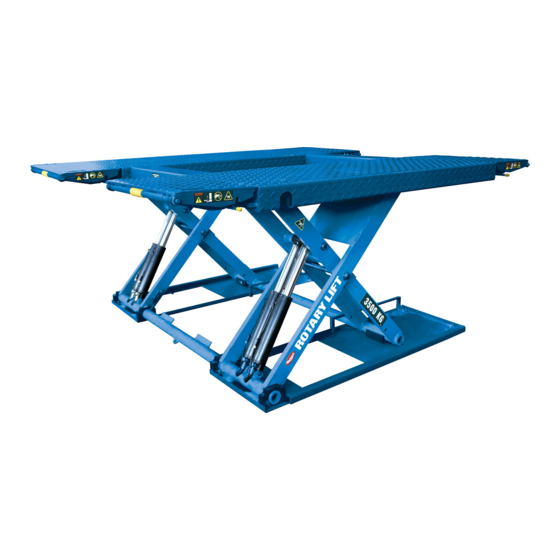
XS35N
(000 Series)
Scissor Lift
Original
O
O
P
P
E
E
R
R
A
A
T
T
I
I
O
O
N
N
&
&
M
M
A
A
I
I
N
N
T
T
E
E
N
N
A
A
N
N
C
C
E
E
M
M
A
A
N
N
U
U
A
A
L
L
XS35N-SMS
Rev.A 25/7/2017
Advertisement
Table of Contents

Subscribe to Our Youtube Channel
Related Manuals for Rotary 000 Series


Summary of Contents for Rotary 000 Series
- Page 1 XS35N (000 Series) Scissor Lift Original & & Installer: Please return this booklet to literature package and give to lift owner/operator. XS35N-SMS Rev.A 25/7/2017 © Rotary Lift, All rights reserved...
-
Page 2: Table Of Contents
Contents Packing, transport and storage Page 3 Introduction Page 4 Chapter 1 Description of the machine Page 4 Chapter 2 Technical specifi cations Page 6 Chapter 3 Safety Page 11 Chapter 4 Installation Page 13 Chapter 5 Operating instructions Page 14 Chapter 6 Maintenance Page 16 Chapter 7 Troubleshooting... -
Page 3: Packing, Transport And Storage
PACKING, TRANSPORT AND STORAGE ALL PACKING, LIFTING, HANDLING, T R A N S P O R T A N D U N PA C K I N G O P E R A T I O N S A R E T O B E P E R F O R M E D E X C L U S I V E L Y B Y E X P E R T P E R S O N N E L W I T H KNOWLEDGE OF THE LIFT AND THE... -
Page 4: Introduction
INTRODUCTION CHAPTRE1 D E S C R I P T I O N O F THE MACHINE CAUTION The electro-hydraulic lift,can be fixed with optional anchor bolts; this means that it is anchored to This manual has been written for the workshop the ground and designed and built for lifting and personnel assigned to using the lift (operator) positionin gautomobiles at a certain height off the... - Page 5 Intend use The scissor lift may only be used: • In indoor areas for lifting unoccupied motor vehicles. • For lifting vehicles with a max.load capacity of 3500KG • If the weight is distributed correctly. By default, the load should be centered in the direction of motion. If the main load (e.g.
-
Page 6: Chapter2 Technical Specifications
CHAPTER2 TECHNICAL SPECIFICATIONS TECHNICAL DATA: Operation.........electro-hydraulic Carrying Capacity......3500kg Lift time..........20sec. Lowering time........20sec. Noisy level........<74 db Weight..........565 kg. approx. Working temperature......-10°C / +40°C Installation requirements: enclosed area. MOTOR Power..........3 Kw Voltage..........230V 1ph Frequency.........50/60 Hz Poles..........2 Speed..........2680 rpm Insulation class........B Absorption:........230V: 18.5A Service..........S3 10Min HYDRAULIC CONTROL UNIT: Type..........Gear pump... - Page 7 HYDRAULIC SYSTEM DIAGRAM...
- Page 9 WIRING SCHEMATIC...
- Page 10 WIRING SCHEMATIC...
-
Page 11: Chapter 3 Safety
Use only qualifi ed lift service personnel and genuine lightened, according to the laws of the country where Rotary parts to make repairs. the lift is installed. 2 - During lifting or lowering operations, the car lift 14 - Climbing on the platforms when lifting the must be operatedonly from the operator’s control... - Page 12 SAFETY DEVICES 1.Buzzer Acoustic alarm.Sounds: When lowering the main lift<120mm(foot protection) 2.Lockable main switch "ON" setting:Scissor lift ready for use. "OFF"setting:Scissor lift out of use.The mains voltage is still present inside the control box. Switching off(OFF) immediately stops any movement of the post lift(=emergency stop) 3.Overfl...
-
Page 13: Chapter 4 Installation
CHAPTER 4 INSTALLATION ATTENTION In case of using the platform in a definite place of WARNING the workshop, it can be chosen to fi xed to the fl oor Unpack the goods and check for possible damage with optional anchor bolts or not fi xed,according to before installing the car lift. -
Page 14: Chapter 5 Operating Instructions
CHAPTER 5 OPERATING INSTRUCTIONS To avoid personal injury and/or property damage, permit only trained personnel WARNING to operate lift. After reviewing these instructions, get familiar with lift controls by running the lift through a few cycles before loading vehicle on lift. ATTENTION Always lift the vehicle using all four rubber pads.Never raise just one end, one corner, or one side. - Page 15 1. Power Switch 2. Power Light 3. Emergency Stop 4. Lower to ground Button 5. Buzzer 6. Raise Button 7. Lower Button Fig. 2 Fig. 2 Small Vehicle Fig. 2 Midsize Vehicle Large Vehicle Fig. 3...
-
Page 16: Chapter 6 Maintenance
• Replace all CAUTION, WARNING, or SAFETY replacement parts for repairs. related decals on the lift if unable to read or missing. Reorder labels from Rotary Lift. • Always keep all bolts and nuts tight. Check periodically. • Always raise lift when cleaning fl oor area. -
Page 17: Chapter 7 Troubleshooting
CHAPTER7 TROUBLE SHOOTING Trouble Cause Remedy Electric motor does not run. 1. Blown fuse or tripped circuit 1. Replace blown fuse or reset breaker. circuit breaker. 2. Incorrect voltage to motor. 2. Supply correct voltage to motor. 3. Damaged wiring connections. 3. -
Page 18: Chapter8 Commissioning
CHAPTER8 COMMISSIONING CHAPTER9 DISPOSAL Check Operation Environmental procedures for disposal Operate lift and assure that push button raises lift ·Prevent environmental hazards. when pushed and stops lift when released. Check ·Avoid contact with or inhalation of toxic sub-stances disconnect switches for cutting power to push- such as hydraulic fl... -
Page 19: Chapter10 Parts Break Down
CHAPTER10 PARTS BREAK DOWN... - Page 20 Detail for Xs35n PartNo. Description AZ-8108 LIMIT SWITCH B20-8X25 HEXAGON SOCKET CAP SCREW B22-8X20 SET SCREW B23-4X20 CROSS RECESS PAN HEAD SCREW B23-4X30 CROSS RECESS PAN HEAD SCREW B25-8X16 INNER HEXAGON CAP SCREW B26-8X80 HEXAGON SOCKET COUNTERSUNK HEAD SCREW B30-8 HEX NUT M8 B40-8 LOCK WASHER Ø8...
- Page 21 Detail for Xs35n Ramp PartNo. Description B60-14 CIRCLIP B61-12 CIRCLIP XX120007 RAMP WELDMENT XX120008 RAMP SUPPORT WELDMENT XX130063 RAMP ROLLER SHAFT XX130064 RAMP ROLLER SHAFT XX130236 RAMP ROLLER XX140009 RAMP ROLLER...
- Page 23 Detail for CONTROL CABINET (XS35NF,1ph 50/60HZ 230V) PartNo. Description XX110016E 4 side open control cabniet (steel parts) P3669 3Ph ,50HZ,400V per unit YBZ-SLYX-10L-L-A Tank AM11-21IAM-3BA2R 3kw motor LSV-08-2NCSP-LM-2H Solenoid valve 24VDC LC3-10-C-2H Coil LSV2-08-2NCP-J-2H Solenoid valve 24VDC LC2-08-2H Coil LPSRV2-08-50 Relier Valve LBZ-T131KK-1 Manifold...
Need help?
Do you have a question about the 000 Series and is the answer not in the manual?
Questions and answers