Table of Contents
Advertisement
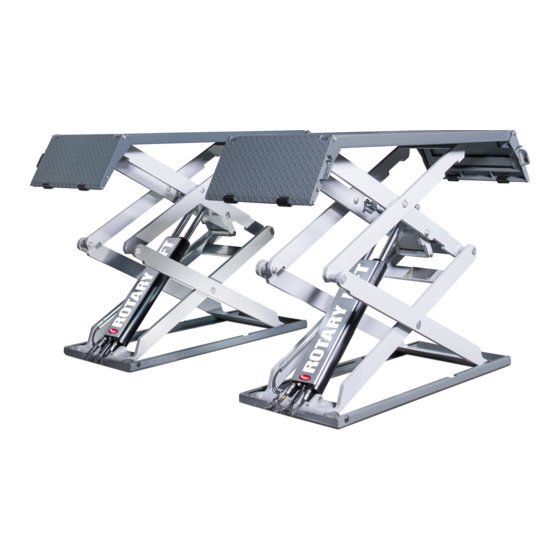
DS35
Installer: Please return this booklet to literature package and give to lift owner/operator.
© Rotary Lift, All rights reserved
3500KG
(200Series)
SJ180507
DS35EX
LP-DS35-2
Rev.C 23/05/2018
O
O
P
P
E
E
R
R
A
A
T
T
I
I
O
O
N
N
&
&
M
M
A
A
I
I
N
N
T
T
E
E
N
N
A
A
N
N
C
C
E
E
M
M
A
A
N
N
U
U
A
A
L
L
Advertisement
Table of Contents
Troubleshooting

Subscribe to Our Youtube Channel
Related Manuals for Rotary DS35EX


Summary of Contents for Rotary DS35EX
- Page 1 Scissor Lift DS35EX/DS35 3500KG (200Series) & & DS35 DS35EX Installer: Please return this booklet to literature package and give to lift owner/operator. LP-DS35-2 SJ180507 Rev.C 23/05/2018 © Rotary Lift, All rights reserved...
- Page 5 Table of Contents Troubleshooting by authorized maintenance contractors ...............22 1. Introduction ..............6. Authorized lowering ........25 About this operating manual ........7 7. Technical data ..........26 Warning and information symbols ......7 8. Cleaning ............32 Intended use ............9 9. Maintenance and repair ........31 Incorrect use, incorrect behavior ......
- Page 6 14.1 Environmental procedures for disposal ....48 14.2 Packaging ..............49 14.3 Oils, grease, and other chemical substances ..49 14.4 Metals / Electronic waste ........49 ANNEX • DS35EX/DS35: Wiring diagrams, Hydraulic circuit diagram, spare parts lists • Protocol of installation • Completion certificate •...
- Page 7 Risk of injury • This operating manual provides information on Potentially hazardous situation. the scissor lift DS35EX/DS35. Non-compliance may lead to • Make sure that you have read and understood minor or moderate injury.
- Page 8 1.2.2 On the product Observe all warning notices on Operating instructions in brief products and ensure they remian legible. These instructions contain information on operation of the control cabinet. WARNING 1.Keep feet away from lifting platform whilst lowering. 2.Ramp support 100% engaged when load on the Warning sticker on control cabinet.
- Page 9 • Intended use Washing cars on the scissor lift. • The scissor lift may only be used: Modifications of any kind. • Internal accident, health and safety, and In indoor areas for lifting unoccupied motor vehi- environmental information cles. • For lifting vehicles with a max.
- Page 10 2. Safety • Do not load lifts beyond the permitted capacity, comply with the permitted axle loads and load 2.1 Operators distribution in accordance with Chapter 2.3. • When disassembling or fitting heavy vehicle The scissor lift may only be operated without parts, watch out for dangerous shifts in the supervision by persons who: weight balance, in particular when the vehicle...
- Page 11 Fig. 1 and 2. Comply with the approved distances between pick-up points as in Fig. 3. Recommended distribution Figure 1&2: DS35/DS35EX: Load capacity 3500kg front max. 3/5:F1: 2100 kg back max.2/5:F2: 1400 kg DS35EX 2.4 Ban on unauthorized modifications or alterations •...
- Page 12 Competent persons Safety inspections by competent persons These are people who have adequate knowledge in the field of lifts based on their professional Safety inspections must be carried out to guar- training and experience antee the safety of lifts. They are sufficiently familiar with health & safety Safety inspections should be carried out in the and accident prevention regulations as well as with following cases:...
- Page 13 Obligations of the plant operator A qualified person is somebody with the training and experience required to possess sufficient knowledge Operation of lifting platforms of lifting platforms and who is sufficiently familiar with the pertinent national regulations, accident prevention In Germany,the use of lifting platforms is governed by the mandatory "Employers' liability insurance regulations and generally acknowledged rules of en- association regulations on health and work safety...
- Page 14 1. Lifting platform 2. Extesnion beam 3. Ramp 4. Scissors 5. Base frame 6. Ramp 7. Control cabinet 8. Hose Cover 9. Recess Box Kit (Only for Flush Mount Accessories) *The DS35EX Control cabinet is slightly different in DS35 different market.
- Page 15 General workflow • Risk of injury in the danger zone of the After determining the vehicle data , the vehicle is scissor lift in the event of incorrect driven over the platform. behavior. WARNING • Only remain in the danger area if you the manufacturer-approved pick-up points on the have been trained and briefed and vehicle are selected and the matching supports...
- Page 16 Safety mechanisms See figures 5 ... 7 Safety mechanisms protect both people and lift. They must not be disabled! WARNING Scissor lift danger zones are protected by safety mechanisms. Function and condition of the safety mecha- nisms must be checked daily! If safety mechanisms are triggered, the scissor lift stops immediately.
- Page 17 3. Independent hydraulic circuits Two hydraulic circuits independent of one another prevent the unintended lowering of the platform. In the event of a break in a hydraulic line in one of the hydraulic circuits, the other hydraulic circuit holds the platform. 4.
- Page 18 A buzzer sounds throughout then entire lowering process. 6. Down button Functions only if the button is pressed,the lift lower. 7. UP button Functions only if the button is pressed,the lift raise. DS35 Control Cabinet (Also DS35EX for ME and Turkey market)
- Page 19 4. Operation Before Loading: • Inspect Lift - See "Operator Inspection And To avoid personal injury and/or prop Maintenance".Never operate if lift malfunctions or erty damage, permit only trained per has broken or damaged parts. sonnel to operate lift. After reviewing these instructions, get familiar with lift DANGER •...
- Page 20 To Raise Lift: • Vehicle is stable on lift; neither front nor tail heavy. • Do Not permit anyone on lift or inside vehicle when it is being raised or lowered. • Actuate RAISE BUTTON. • Raise vehicle until tires clear the floor. •...
- Page 21 While Using Lift: 5. Problems, causes, actions The following lists contain information on pote- • Avoid excessive rocking of vehicle while on lift. ntial problems,their causes, and actions to rect- ify the fault. • Always use safety stands as needed for stability when removing or installing heavy components.
- Page 22 Problem Possible cause Actions • Blown fuse or circuit breaker. 1. Replace blown fuse or reset circuit breaker(customer side). The motor is not running. • Overhead Sensor Actuated. 2.Check sensor or incorrect connection. 3.Check UP button. • Up button not functioning. 4.
- Page 23 6. Low oil level. 6. Fill tank to proper level . 7. Improper relief valve adjustment. 7. Replace relief valve. 8. Open lowering valve. 8. Repair/replace lowering valve. Lift slowly settles down. 1. Debris in check valve seat. 1. Clean check valve. 2.
- Page 24 Anchors will not stay tight. 1. Holes drilled oversize. 1. Relocate lift using new bit to drill 2. Concrete floor thickness or holes. Reference installation holding strength not sufficient. instructions for proper anchoring method and minimum spacing requirements. 2. Break out old concrete and re- pour new pads for lift per lift installation instruction.
- Page 25 6 Authorized lowering f the car lift cannot perform lowering operations be- cause of power supply interruption, faulty hydraulic valves, or electric trouble in the system, the lift can be lowered manually. For manual lowering operation (emergency), perform the following: Manual lowering (emergency) opera tions should be preformed by autho rized personnel specially trained for...
- Page 26 7. Technical data...
- Page 32 8. Cleaning 9. Maintenance and repair • Only clean the lift when not loaded (without Inadequate maintenance and repair vehicle). work may cause serious injury and also lead to damage to property. A • Clean main lift, and all work areas daily. In doing safety risk as well as a risk of fatal DANGER injury exists during operation.
- Page 33 • 9.3 Maintenance work Prevent environmental hazards: • Mineral-oil-based hydraulic oil is combustible Potential crushing and shearing and a water pollutant. It must only be used in hazard to limbs caused by unc- conjunction with the relevant safety data she- ontrolled lowering motion.
- Page 34 • Replace all CAUTION, WARNING, or SAFETY related decals on the lift if unable to read or • Daily: Inspect rubber blocks for damage or missing. Reorder labels from Rotary Lift. excessive wear. Replace as required with genuine Rotary parts.
- Page 35 9.4 Approved hydraulic oils 9.5 Check, refill, change the hydraulic Important information Risk to people and the environment • from toxic substances when filling Only use hydraulic oils in accordance with DIN the hydraulic oil tank. 51524 for the hydraulic system. •...
- Page 36 9.6 Repair work (Repairs) If repairs are carried out incorre- ctly, they may cause serious injury and also lead to damage to prope- rty. A safety risk as well as a risk DANGER of fatal injury exists during operation. Repairs may only be carried out by trained customer service staff.
- Page 37 10. Transport, Storage Cylinder Rebuilding(for changing the seal kit) Crushing and shearing hazard 1) Remove manual bleeder and extend plunger for limbs when unloading. from casing. Caused by collapsing or slip DANGER 2) Remove piston retaining ring or clip. ping of the load. 3) Remove plunger from casing.
- Page 38 10.1 Transport Base lift package The lift is supplied in a packing unit (base unit) plus a separate control cabinet . The packing unit comes with the following documentation: • Transport description giving suitable suspension points, total weight, centre of gravity, required cable lengths, transport locks, etc.
- Page 39 11. Assembly(installation) 11.2 Site specifications • The scissor lift may only be installed above Incorrect installation work may lead ground and indoors. • to serious injury and material Refer to the building plans when selecting a site. • damage. A safety risk as well as a When anchoring to the floor, take into account risk of fatal injury exists during DANGER...
- Page 40 Fig. 17. Operator should be in a position to notice any misalignment of lifting pads or vehicle during 11.5 Control Cabinet Connections operation. Rotary Lift does not recommend placing • the control cabinet in a different location orientation Electrical Connection:...
- Page 41 Connect One Platform Top Limit Switch and Stop Down Switch Connect One Platform Top Limit Switch...
- Page 42 Transformer 230V 400V 11 12 13 14 15 16 11 12 13 14 15 16 Green Blue Green Blue...
- Page 43 Fig. 18 and Fig. 19. 2. Connect hydraulic hoses “A” and “B” to the power unit as shown in Fig. 20. Power Unit EPL8-03 EPY8 Y FITTING Hose C DSS35-9801-3L(DS35EX) DSS35-9801-3S (DS35) Hose D Hose B Hose A DSS35-9801-1L(DS35EX) DSS35-9801-4L(DS35EX) DSS35-9801-2L(DS35EX) DSS35-9801-1(DS35)
- Page 44 11.7 Final Positioning of Platforms Make sure the platforms or 1. Verify the platform bases are square and the scissors can not fall down when distance between the platforms is correct. you work under the platforms. 2. Verify platform bases are level, Fig. 22 NP945 REV.- 3.
- Page 45 Drill holes using Clean Hole correct carbide tipped masonry bit 11.8 Anchoring drill bit. 1. Turn the disconnect switch to “ON” and press the “UP” button to raise the platforms which provides room under the platforms for drilling. 2. Concrete shall have a compression strength of at least C20/25 and a minimum thickness of 160mm.Drill (8) holes with required diameter in the concrete floor.and install (8) eight lift anchors...
- Page 46 XX100003) or Recess Box Flush Mount Kit (part # all hose covers securely, Fig. 27. XX100024/XX100014). Please contact the phone DS35EX number listed on the front cover of the manual for additional assistance. The Full Flush Mount Kit contains frame components with concrete ties that will need to be placed during concrete pour.
- Page 47 DS35EX too hard.(This will not damage the lift, but will be loud and may be disturbing to technicians.) 3.
- Page 48 13. Disassembly 12. Commissioning • 12.1 Check Operation Disassembly work may only be carried out by authorized qualified staff. Operate lift and assure that push button raises lift • when pushed and stops lift when released. Check Only qualified electricians may work on the elec- disconnect switches for cutting power to push- trics.
- Page 49 Notes • Oils and lubricants are water pollutants under the terms of the Water Management Act WGH. Always dispose of these in an environmentally friendly manner in compliance with the regula- tions which apply in your country. • Hydraulic oil-based on mineral oil is a water pol- lutant and is combustible.
- Page 50 Annex Scissor lift DS35EX DS35 Series 200...
- Page 51 3625 psi Relief Valve 250 bar Pump Motor Filter YG80-9100G YG82-9100G XX140010 XX140011 Power Unit EPC8-G02 M130028Y FJ7352-3 EPL8-03 EPY8 Y FITTING FJ7352-3 Hose C XX140064 DSS35-9801-3L(DS35EX) DSS35-9801-3S(DS35) Hose D Hose B Hose A DSS35-9801-4L(DS35EX) DSS35-9801-2L(DS35EX) DSS35-9801-1L(DS35EX) DSS35-9801-4S(DS35) DSS35-9801-2(DS35) DSS35-9801-1(DS35)
- Page 52 II. Electric wiring diagram...
- Page 55 Annex III. Parts Break Down DS35EX...
- Page 56 DS35EX...
- Page 57 Detail for PB-DS35EX01 PartNo. Description B201-10*65 Hex socket head screw M10*65 B21-4*6 Hex socket set screw with flat pointM4*6 B21-6*10 Hex socket set screw with flat pointM6*10 B25-6*12 Hex socket pan head screw M6*12 B25-6*80 Hex socket pan head screw M6*80 B25-8*20 Hex socket pan head screw M8*20 B30-6...
- Page 58 XX140015Y Bearing 25 dia*35 long XX140017Y Bearing 30 dia*50 long XX140019Y Bearing 25 dia*50 long XX140021 XX140022 XX140023 XX140024 XX140025 XG130007 M20*1.0 slotted round lockunt XX140029 Wahser XX140062 Bearing XX140064 Velocity valve XX140066 Sensor block DS35...
- Page 59 DS35...
- Page 60 Detail for PB-DS35/32-01 PartNo. Description B201-10*65 Hex socket head screw M10*65 B21-4*6 Hex socket set screw with flat pointM4*6 B21-6*10 Hex socket set screw with flat pointM6*10 B25-6*12 Hex socket pan head screw M6*12 B25-6*80 Hex socket pan head screw M6*80 XX140066 Sensor block B30-6...
- Page 61 XX140017Y Bearing 30 dia*50 long XX140019Y Bearing 25 dia*50 long XX140021 XX140022 XX140023 XX140024 XX140025 XX140029 Wahser XX140062 Bearing XX140066 Sensor block XX110006 Detail for XX110006 Kicker assembly PartNo. Description B60-20 Circlip Φ20 XX120020 Kicker weld XX130036 Roller pin XX140019Y Bearing 25dia*50long XX140035 Roller...
- Page 62 Detail for Rubber pad for DS35EX PartNo. Description XX140075 30mm rubber pad XX140076 70mm rubber pad *For The Middle East and Turkey Market DS35EX use Below rubber pad (FJ2427/2428/SB700071Y) Detail for Rubber pad for DS35 PartNo. Description FJ2427Y 38 mm rubber pad FJ2428Y...
- Page 63 Detail for Hose cover(DS35EX) PartNo. Description XX130091CN Hose cover 827mm B41-8 Flat washer 8 XX130111 Hose Cover 970mm DS35EX XX130141 Hose Cover 45° XX130156 Hose Cover 550mm B14B-6*40 Nylon anchors Detail for Hose cover(DS35) PartNo. Description XX130091CN Hose cover 827mm...
- Page 64 Control cabinet assembly for DS35EX (Not ME and Turkey market)
- Page 65 Fiiting on P1/P2 Port EPL8-03 Air fitting EPY8 Y fitting Black Air tube 8mm(in parts box) DS35D0-DQ4-2 EV1 Wire kit DS35D0-DQ4-1 EV2 Wire kit DS35EX-DQ4-4 Power cable 4*1.5² DS35D0-DQ4-3 Motor cable 4*1.5² * Note: Item 26/27/28/29 not show on the drawing.
- Page 66 Control cabinet assembly for DS35EX (Not ME and Turkey market)
- Page 67 EV2 Wire kit FJ7352-3 & M130028Y Fiiting on P1/P2 Port EPL8-03 Air fitting EPY8 Y fitting Black Air tube 8mm (in parts box) DS35EX-1PH-DQ4-4 Power cable 3*2.5² DS35N0-DQ4-3 Motor cable 3*2.5² * Note: Item 26/27/28/29 not show on the drawing.
- Page 68 Control cabinet assembly for DS35EX (Not ME and Turkey market)
- Page 69 FKZJ-131A Addational manifold with solenoid DS35D0-DQ4-2 EV1 Wire kit DS35D0-DQ4-1 EV2 Wire kit DS35D0-DQ4-3 Motor cable 4*1.5² DS35EX-DQ4-4 Power cable 4*1.5² DSS35-9801-8 Hydraulic hose FJ7352-3 Fiiting on P1/P2 Port on Addational manifold EPL8-02 Air fitting(on the power unit tank) EPY8...
- Page 70 Control cabinet assembly for DS35 (Also DS35EX for ME and Turkey market)
- Page 71 Fiiting on P1/P2 Port EPL8-03 Air fitting EPY8 Y fitting Black Air tube 8mm(in parts box) DS35D0-DQ4-2 EV1 Wire kit DS35D0-DQ4-1 EV2 Wire kit DS35EX-DQ4-4 Power cable 4*1.5² DS35D0-DQ4-3 Motor cable 4*1.5² * Note: Item 25-33 not show on the drawing.
- Page 72 Control cabinet assembly for DS35 (Also DS35EX for ME and Turkey market)
- Page 73 DS35D0-DQ4-3 Motor cable 4*1.5² DS35D0-DQ4-2 EV1 Wire kit DS35D0-DQ4-1 EV2 Wire kit DSS35-9801-8 Hydraulic hose DS35EX-DQ4-4 Power cable 4*1.5² EPL8-02 Air fitting(on the power unit tank) EPY8 Y fitting Black Air tube 8mm(in parts box) FJ7352-3 Fiiting on P1/P2 Port Addational manifold...
- Page 74 Control cabinet assembly for DS35 (Also DS35EX for ME and Turkey market)
- Page 75 Fiiting on P1/P2 Port EPL8-03 Air fitting EPY8 Y fitting Black Air tube 8mm(in parts box) DS35D0-DQ4-2 EV1 Wire kit DS35D0-DQ4-1 EV2 Wire kit DS35EX-1PH-DQ4-4 Power cable 3*2.5² DS35N0-DQ4-3 Motor cable 3*2.5² * Note: Item 23-30 not show on the drawing.
- Page 76 PartNo. Description XX130270 Ramp weldment B14B-6*40 Nylon anchors B41-8 Flat washer 8 Only for DS35EX Accessory 2 Detail for Sports ramp SPRMP-DS35EX PartNo. Description XX130270 Ramp weldment XX130525 Ramp weldment B14B-6*40 Nylon anchors B25-8*20 Hex socket pan head screw M8*20...
- Page 77 Accessory 3 *If only order recess weldment XX120022,the partno of set is XX100062. Only for DS35 Detail for XX100003 PartNo. Description B10-8*14 Bolt B14B-6*40 Nylon anchor B40-8 Lock washer 8 B41-8 Flat washer 8 XX120022 Recess weldment XX120030 Recess box weldment XX130200 Short hose cover Accessory 4...
- Page 78 Accessory 5 *If only order recess weldment XX120055,the partno of set is XX100063. Only for DS35EX Detail for XX100025 PartNo. Description XX120060 Recess Box welement B14B-6*40 Nylon anchor XX120030 Recess Box weldment B41-8 Flat washer 8 XX120055 Recess weldment Accessory 6...
- Page 79 All Shafts kit for one platform Part.No Description GLP35-D3 Shim kit for leveing Part.No Description Proximity switch XG130075 Part.No Description Hose for DS35EX DSS35-9801-1L Hose for DS35EX DSS35-9801-2L Hose for DS35EX DSS35-9801-3L DSS35-9801-4L Hose for DS35EX DSS35-9801-1 Hose for DS35 Hose for DS35...
- Page 80 Part.No Description XX140075 Rubber pad 30mm XX140076 Rubber pad 70mm PartNo. Description FJ2427Y Rubber pad 38mm FJ2428Y Rubber pad 76mm SB700071Y Rubber pad 13mm Part.No Description XX140009 Ramp roller 95mm L XX130236 Ramp roller 30mm L Part.No Description XX140010 Master Cylinder XX140011 Slave Cylinder Other hydraulic components...
- Page 81 Protocol of installation The lift, designation............(Address)... / • After successful installation please filled completely this form, tick applicable points and sign the form. • Copy the original and send them to the manufacturer within a week. • Leave a copy in the test book. The vehicle lift, Type .............
- Page 82 Completion certificate The vehicle lift Type ............. Machine -/serial number: ............. was on ............. by the company ............. (Address) ............. installed, checked for function and safety and put into operation. The following persons (operators) have been instructed in the handling of the vehicle lift by the trained installer of the manufacturer or contractor (expert) after the installation of the vehicle lift.
- Page 83 ATTACHMENT Scissor Lift DS35EX DS35 Maintenance schedule: Notes for execution of the visual and functional testing...
- Page 84 Notes for execution of the visual and functional testing In the scope of periodical inspections, the followings must be checked in particular: 1. Information on the lifting platform Object to be checked Nameplate Fastening Labeling Readability Summary of the manual Completeness 2.Detailed operating instructions Condition...
- Page 85 10. Load suspension devices Protection against sliding Condition Roll-off protection Function Holding device Protection of the hinged bracket Safety fence Condition Corrosion Fastening and securing of removable parts Effectiveness of locking mechanisms Mobility of movable parts Ground Surefootedness Deformation Corrosion Fastening and securing of removable parts Parallel motion on operating platforms Condition...
- Page 86 Chain wheels Condition Sprockets Function Clamping device Condition Securing of the chain guide Function 13. Spindles Storage Deformation Contamination Wear of the threads Notches Striations Grooves, applications Efficiency of the covering Main nut Wear of the thread (play) Compensation ring Bearing Condition Notches...
- Page 87 Filters External condition Pressure control valve External condition Lead seal undamaged 16. Pneumatics Lines Leakage Line connections Fastening Damage Deformation Corrosion Hoses Fastening Hose connections Damage Brittleness Porosity Cylinders Fastening, cracks, pipe connections and hose connections Tightness of the sleeves Pistons Surface of the piston rod, striations, contami- nation...
- Page 88 ATTACHMENT Scissor Lift Inspection log...
- Page 89 Inspection log Scissor Lift Type: Serial number: Year of construction: Operator: Day of first commissioning:...
- Page 91 Test Report Of a periodic /special examination The lifting platform underwent an examination regarding operational readiness on The following/no*) faults found. Test scope Still pending Partial tests There are no*) reasons against continued operation, retesting is not*) required. The technical expert/surveyor (Place ,date) (Signature) Name and address...
- Page 93 Test Report Of a periodic /special examination The lifting platform underwent an examination regarding operational readiness on The following/no*) faults found. Test scope Still pending Partial tests There are no*) reasons against continued operation, retesting is not*) required. The technical expert/surveyor (Place ,date) (Signature) Name and address...
- Page 95 Test Report Of a periodic /special examination The lifting platform underwent an examination regarding operational readiness on The following/no*) faults found. Test scope Still pending Partial tests There are no*) reasons against continued operation, retesting is not*) required. The technical expert/surveyor (Place ,date) (Signature) Name and address...
- Page 97 Test Report Of a periodic /special examination The lifting platform underwent an examination regarding operational readiness on The following/no*) faults found. Test scope Still pending Partial tests There are no*) reasons against continued operation, retesting is not*) required. The technical expert/surveyor (Place ,date) (Signature) Name and address...
- Page 99 Test Report Of a periodic /special examination The lifting platform underwent an examination regarding operational readiness on The following/no*) faults found. Test scope Still pending Partial tests There are no*) reasons against continued operation, retesting is not*) required. The technical expert/surveyor (Place ,date) (Signature) Name and address...
- Page 101 Test Report Of a periodic /special examination The lifting platform underwent an examination regarding operational readiness on The following/no*) faults found. Test scope Still pending Partial tests There are no*) reasons against continued operation, retesting is not*) required. The technical expert/surveyor (Place ,date) (Signature) Name and address...
- Page 103 Test Report Of a periodic /special examination The lifting platform underwent an examination regarding operational readiness on The following/no*) faults found. Test scope Still pending Partial tests There are no*) reasons against continued operation, retesting is not*) required. The technical expert/surveyor (Place ,date) (Signature) Name and address...
- Page 105 Test Report Of a periodic /special examination The lifting platform underwent an examination regarding operational readiness on The following/no*) faults found. Test scope Still pending Partial tests There are no*) reasons against continued operation, retesting is not*) required. The technical expert/surveyor (Place ,date) (Signature) Name and address...
- Page 107 Test Report Of a periodic /special examination The lifting platform underwent an examination regarding operational readiness on The following/no*) faults found. Test scope Still pending Partial tests There are no*) reasons against continued operation, retesting is not*) required. The technical expert/surveyor (Place ,date) (Signature) Name and address...
- Page 109 Test Report Of a periodic /special examination The lifting platform underwent an examination regarding operational readiness on The following/no*) faults found. Test scope Still pending Partial tests There are no*) reasons against continued operation, retesting is not*) required. The technical expert/surveyor (Place ,date) (Signature) Name and address...
- Page 111 Test Report Of a periodic /special examination The lifting platform underwent an examination regarding operational readiness on The following/no*) faults found. Test scope Still pending Partial tests There are no*) reasons against continued operation, retesting is not*) required. The technical expert/surveyor (Place ,date) (Signature) Name and address...
- Page 113 Test Report Of a periodic /special examination The lifting platform underwent an examination regarding operational readiness on The following/no*) faults found. Test scope Still pending Partial tests There are no*) reasons against continued operation, retesting is not*) required. The technical expert/surveyor (Place ,date) (Signature) Name and address...
- Page 115 Alterations and substantial repairs Type Date/Name...
- Page 116 Contact Your Nearest Authorized Rotary Parts Distributor. For Genuine Rotary Replacement Parts. Please see the parts breakdown. DATE REV. CHANGE MADE 10-10-17 New annex manual for DS35/DS35EX Lift release. 15-03-18 B Change to new Up button DS35-DQ-ZP1G(01/2018),new wiring diagram .
Need help?
Do you have a question about the DS35EX and is the answer not in the manual?
Questions and answers