Table of Contents
Advertisement
Quick Links
Advertisement
Table of Contents

Related Manuals for Pepperl+Fuchs PS1000-A6-12.16


Summary of Contents for Pepperl+Fuchs PS1000-A6-12.16
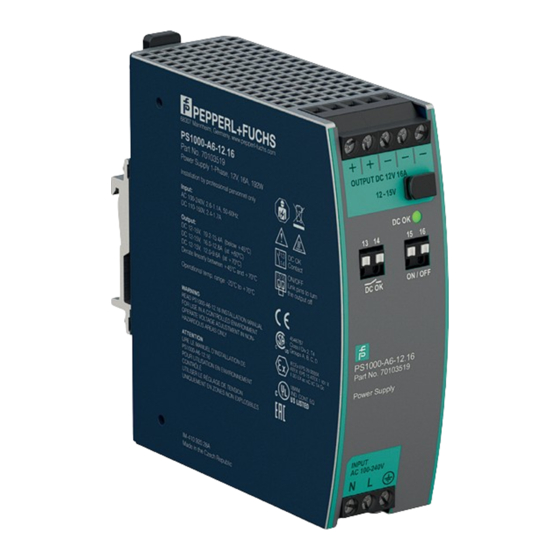
- Page 1 PS1000-A6-12.16 Power Supply Technical Information ISO9001...
- Page 2 Phone: +49 621 776 - 0 E-mail: info@de.pepperl-fuchs.com North American Headquarters Pepperl+Fuchs Inc. 1600 Enterprise Parkway Twinsburg, Ohio 44087 Phone: +1 330 425-3555 E-mail: sales@us.pepperl-fuchs.com Asia Headquarters Pepperl+Fuchs Pte. Ltd. P+F Building 18 Ayer Rajah Crescent Singapore 139942 Phone: +65 6779-9091 E-mail: sales@sg.pepperl-fuchs.com https://www.pepperl-fuchs.com...
-
Page 3: Table Of Contents
Power Supply PS1000-A6-12.16 Contents Introduction ............5 Terminology and Abbreviations. - Page 4 Power Supply PS1000-A6-12.16 Contents Physical Dimensions and Weight........35 Accessories .
-
Page 5: Introduction
Power Supply PS1000-A6-12.16 Introduction Introduction The information given in this document is correct to the best of our knowledge and experience at the time of publication. If not expressly agreed otherwise, this information does not represent a warranty in the legal sense of the word. As the state of our knowledge and experience is constantly changing, the information in this data sheet is subject to revision. -
Page 6: Terminology And Abbreviations
Power Supply PS1000-A6-12.16 Terminology and Abbreviations Terminology and Abbreviations PE and symbol PE is the abbreviation for Protective Earth and has the same meaning as the symbol Earth, Ground This document uses the term earth which is the same as the U.S. term ground. -
Page 7: Intended Use
Power Supply PS1000-A6-12.16 Intended Use Intended Use This device is designed for installation in an enclosure and is intended for the general professional use such as in industrial control, office, communication, and instrumentation equipment. Do not use this power supply in equipment, where malfunction may cause severe personal injury or threaten human life. -
Page 8: Installation Instructions
Power Supply PS1000-A6-12.16 Installation Instructions Installation Instructions Warning! Risk of electrical shock, fire, personal injury or death. • Do not use the power supply without proper grounding (Protective Earth). Use the terminal on the input block for earth connection and not one of the screws on the housing. -
Page 9: Ac Input
Power Supply PS1000-A6-12.16 AC Input AC Input AC input Nom. AC 100-240V Suitable for TN-, TT- and IT mains networks AC input range Min. 85-264Vac Continuous operation Min. 264-300Vac For maximal 500ms Allowed voltage L or N to earth Max. - Page 10 Power Supply PS1000-A6-12.16 AC Input Input C urrent, typ. a) 100Vac b) 120Vac c) 230Vac Output C urrent 8 10 12 14 16 Figure 5.3 Input current vs. output current at 12V output voltage P ower F actor, typ. 0.95 (a) 100Vac, 0.85...
-
Page 11: Dc Input
Power Supply PS1000-A6-12.16 DC Input DC Input Input voltage DC Nom. DC 110-150V ±20% Input voltage range DC Min. 88-180Vdc DC input current Typ. 1.90A At 110Vdc, 12V, 16A Typ. 1.38A At 150Vdc, 12V, 16A Typ. 0.68A At 300Vdc, 12V, 16A Allowed voltage L/N to earth Max. -
Page 12: Input Inrush Current
Power Supply PS1000-A6-12.16 Input Inrush Current Input Inrush Current An active inrush limitation circuit (NTCs, which are bypassed by a relay contact) limits the input inrush current after turn-on of the input voltage. The charging current into EMI suppression capacitors is disregarded in the first microseconds after switch-on. -
Page 13: Output
Power Supply PS1000-A6-12.16 Output Output Output voltage Nom. 12Vdc Adjustment range Min. 12-15Vdc Guaranteed value Max. 16.5Vdc This is the maximum output voltage which can occur at the clockwise end position of the potentiometer due to tolerances. It is not a guaranteed value which can be achieved. - Page 14 Power Supply PS1000-A6-12.16 Output Output Voltage Adjustment R ange C ontinuous current Hiccup P LUS mode Output C urrent Figure 8.1 Output voltage vs. output current, typ. Output Voltage (dynamic behavior, < 12ms ) Adjus tment R ange Output C urrent Figure 8.2...
-
Page 15: Hold-Up Time
Power Supply PS1000-A6-12.16 Hold-Up Time Hold-Up Time AC 100V AC 120V AC 230V Hold-up Time Typ. 108ms 108ms 108ms At 12V, 8A, see Figure 9.1 Min. 81ms 81ms 81ms At 12V, 8A, see Figure 9.1 Typ. 50ms 50ms 50ms At 12V, 16A, see Figure 9.1 Min. -
Page 16: Dc-Ok Relay Contact
Power Supply PS1000-A6-12.16 DC-OK Relay Contact DC-OK Relay Contact This feature monitors the output voltage on the output terminals of a running power supply. Contact closes As soon as the output voltage reaches typ. 90% of the adjusted output voltage level. -
Page 17: Remote On/Off Function
Power Supply PS1000-A6-12.16 Remote On/Off Function Remote On/Off Function This feature allows to switch-off the power supply output with a signal switch or transistor. A link between pin 15 and 16 turns the power supply off. Pin 15 is referenced to the (-) output voltage. -
Page 18: Efficiency And Power Losses
Power Supply PS1000-A6-12.16 Efficiency and Power Losses Efficiency and Power Losses AC 100V AC 120V AC 230V Efficiency typ. 92.1% 92.8% 94.3% At 12V, 16A typ. 92.0% 92.7% 94.2% At 12V, 19.2A Average efficiency typ. 91.6% 92.2% 93.3% At 25% at 4A, 25% at 8A, 25% at 12A. - Page 19 Power Supply PS1000-A6-12.16 Efficiency and Power Losses E fficiency Input Voltage 230 264Vac Figure 12.3 Efficiency vs. input voltage at 12V, 16A, typ. P ower L osses Input Voltage 230 264Vac Figure 12.4 Losses vs. input voltage at 12V, 16A, typ.
-
Page 20: Lifetime Expectancy
Power Supply PS1000-A6-12.16 Lifetime Expectancy Lifetime Expectancy The Lifetime expectancy shown in the table indicates the minimum operating hours (service life) and is determined by the lifetime expectancy of the built-in electrolytic capacitors. Lifetime expectancy is specified in operational hours and is calculated according to the capacitor's manufacturer specification. -
Page 21: Mtbf
Power Supply PS1000-A6-12.16 MTBF MTBF MTBF stands for Mean Time Between Failure, which is calculated according to statistical device failures, and indicates reliability of a device. It is the statistical representation of the likelihood of a unit to fail and does not necessarily represent the life of a product. -
Page 22: Functional Diagram
Power Supply PS1000-A6-12.16 Functional Diagram Functional Diagram Output Voltage R egulator Input F us e Input F ilter Output P ower P F C F ilter C onverter Input R ectifier C onverter Inrus h C urrent Limiter DC -ok... -
Page 23: Terminals And Wiring
Power Supply PS1000-A6-12.16 Terminals and Wiring Terminals and Wiring The terminals are IP20 finger safe constructed and suitable for field- and factory wiring. Input and output DC-OK-Signal, Shut-down input Type Screw terminals Push-in terminals Solid wire Max. 6mm Max. 1.5mm Stranded wire Max. - Page 24 Power Supply PS1000-A6-12.16 Terminals and Wiring Dis tribution Terminals P ower P ower S upply S upply L oad Output Output Figure 16.2 Using distribution terminals...
-
Page 25: Front Side And User Elements
Power Supply PS1000-A6-12.16 Front Side and User Elements Front Side and User Elements Output Terminals (screw terminal, two identical + poles and three identical - poles) Positive output – Negative (return) output Output Voltage Potentiometer OUTPUT DC 12V 16A 12 -15V Open the flap to adjust the output voltage. -
Page 26: Emc
Power Supply PS1000-A6-12.16 The power supply is suitable for applications in industrial environments as well as in residential, commercial and light industry environments. EMC Immunity According to generic standards: EN 61000-6-1 and EN 61000-6-2 Electrostatic discharge EN 61000-4-2 Contact discharge... - Page 27 Power Supply PS1000-A6-12.16 Switching Frequencies PFC converter 110kHz Fixed frequency Main converter 84kHz to 140kHz Output load dependent Auxiliary converter 60kHz Fixed frequency...
-
Page 28: Environment
Power Supply PS1000-A6-12.16 Environment Environment Operational temperature -25°C to +70°C (-13°F to 158°F) Reduce output power according to Figure 19.1 Storage temperature -40°C to +85°C (-40°F to 185°F) For storage and transportation Output de-rating 2.5W/°C Between +45°C and +60°C (113°F to 140°F) 4.8W/°C... - Page 29 Power Supply PS1000-A6-12.16 Environment Allowed Output C urrent at 12V 2000m 4000m 6000m Altitude Figure 19.2 Output current vs. altitude...
-
Page 30: Protection Features
Power Supply PS1000-A6-12.16 Protection Features Protection Features Output protection Electronically protected against overload, no-load and short-circuits. In case of a protection event, audible noise may occur. Output over-voltage protection Typ. 18.2Vdc In case of an internal power supply defect, Max. 19Vdc a redundant circuit limits the maximum output voltage. -
Page 31: Safety Features
Power Supply PS1000-A6-12.16 Safety Features Safety Features Input / output separation Double or reinforced galvanic isolation SELV IEC/EN 60950-1 PELV IEC/EN 60204-1, EN 50178, IEC 62103, IEC 60364-4-41 Class of protection PE (Protective Earth) connection required Isolation resistance > 500MOhm... -
Page 32: Dielectric Strength
Power Supply PS1000-A6-12.16 Dielectric Strength Dielectric Strength The output voltage is floating and has no ohmic connection to the ground. Type and factory tests are conducted by the manufacturer. Field tests may be conducted in the field using the appropriate test equipment which applies the voltage with a slow ramp (2s up and 2s down). -
Page 33: Approvals
Power Supply PS1000-A6-12.16 Approvals Approvals EU Declaration of Conformity Trade conformity assessment for Europe The CE mark indicates conformance with the European • ATEX directive • EMC directive • Low-voltage directive (LVD) • RoHS directive UL 61010-2-201 UL Certificate (former UL 508) -
Page 34: Other Fulfilled Standards
Power Supply PS1000-A6-12.16 Other Fulfilled Standards Other Fulfilled Standards RoHS Directive Directive 2011/65/EU of the European Parliament and the Council of June 8 , 2011 on the restriction of the use of certain hazardous substances in electrical and electronic equipment. - Page 35 Power Supply PS1000-A6-12.16 Physical Dimensions and Weight Physical Dimensions and Weight Width 39mm, 1.54 inch Height 124mm, 4.88 inch Depth 117mm, 4.61 inch The DIN mounting rail height must be added to the unit depth to calculate the total required installation depth.
- Page 36 Power Supply PS1000-A6-12.16 Accessories Accessories PS1000-D2-24.40.RM – Redundancy Module The redundancy module is equipped with two input channels, which are individually decoupled by utilizing MOSFET technology. Using MOSFETs instead of diodes reduces the heat generation and the voltage drop between input and output.
- Page 37 Power Supply PS1000-A6-12.16 Application Notes Application Notes 27.1 Peak Current Capability The unit can deliver peak currents (up to several milliseconds) which are higher than the specified short term currents. This helps to start current demanding loads. Solenoids, contactors and pneumatic modules often have a steady state coil and a pick-up coil.
- Page 38 Power Supply PS1000-A6-12.16 Application Notes 5.8V 12ms Output Voltage Output C urrent 10ms /DIV Figure 27.3 48A peak current for 12ms , typ. (3x the nominal current) Note The DC-OK relay triggers when the voltage dips more than 10% for longer than 1ms.
- Page 39 Power Supply PS1000-A6-12.16 Application Notes 27.4 Output Circuit Breakers Standard miniature circuit breakers (MCB’s or UL 1077 circuit breakers) are commonly used for AC-supply systems and may also be used on 12V branches. MCB’s are designed to protect wires and circuits. If the ampere value and the characteristics of the MCB are adapted to the wire size that is used, the wiring is considered as thermally safe regardless of whether the MCB opens or not.
- Page 40 Power Supply PS1000-A6-12.16 Application Notes 27.5 Parallel Use to Increase Output Power Power supplies can be paralleled to increase the output power. The output voltage of all power supplies shall be adjusted to the same value (±100mV) with the same load conditions on all units, or the units can be left with the factory settings.
- Page 41 Power Supply PS1000-A6-12.16 Application Notes 27.6 Parallel Use for Redundancy Power supplies can be paralleled for redundancy to gain higher system availability. Redundant systems require a certain amount of extra power to support the load in case one power supply unit fails. The simplest way is to put two decoupled power supplies in parallel.
- Page 42 Power Supply PS1000-A6-12.16 Application Notes 27.7 Series Operation Power supplies of the same type can be connected in series for higher output voltages. It is possible to connect as many units in series as needed, providing the sum of the output voltage does not exceed 150Vdc.
- Page 43 Power Supply PS1000-A6-12.16 Application Notes 27.9 Charging of Batteries The power supply can be used to charge lead-acid or maintenance free batteries (SLA or VRLA batteries). Charging Batteries Set output voltage (measured at no load and at the battery end of the cable) very precisely to the end-of-charge voltage, see table below.
- Page 44 Power Supply PS1000-A6-12.16 Application Notes 27.11 Use in a Tightly Sealed Enclosure When the power supply is installed in a tightly sealed enclosure, the temperature inside the enclosure will be higher than outside. In such situations, the inside temperature defines the ambient temperature for the power supply.
- Page 45 Power Supply PS1000-A6-12.16 Application Notes OUTP UT Output C urrent P ower S upply Ambient T emperature INP UT 60°C Figure 27.9 Mounting orientation A (standard orientation) Output C urrent Ambient T emperature 60°C Figure 27.10 Mounting orientation B (upside down)
- Page 46 Pepperl+Fuchs Quality Download our latest policy here: www.pepperl-fuchs.com/quality www.pepperl-fuchs.com © Pepperl+Fuchs · Subject to modifications Printed in Germany DOCT-7383...
Need help?
Do you have a question about the PS1000-A6-12.16 and is the answer not in the manual?
Questions and answers