
Related Manuals for Pepperl+Fuchs PS3500 N+1


Summary of Contents for Pepperl+Fuchs PS3500 N+1
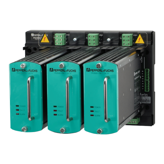
- Page 1 PROCESS AUTOMATION PS3500 N+1 REDUNDANT POWER SUPPLY INSTALLATION & OPERATION MANUAL...
-
Page 2: Table Of Contents
PS3500 N+1 Redundant Power Supply Contents Introduction ........................2 Instructions ........................3 Intended use ......................4 Product label ......................4 Mounting ........................ 5 Specifications ....................... 5 Power supply module specifications ..............5 System specifications .................... 6 Dimensions ......................8 Temperature considerations ..................9 Convection cooling .................... -
Page 3: Introduction
PS3500 N+1 Redundant Power Supply Introduction This manual applies to the Pepperl+Fuchs PS3500 system that consists of the products shown in Table 1: Model number Description PS3500-PM-1.24.15 N+1 power supply module, 24 V DC @ 15 A PS3500-TB-3 Backplane for three power modules and one diagnostic module... -
Page 4: Instructions
PS3500 N+1 Redundant Power Supply Instructions 2.1 Intended use The PS3500 product range may be installed in Zone 2 or Class I/Division 2 hazardous areas. Type of protection is Ex nA nC (non-arcing, sealed device) for Zone 2 Gas Groups IIC, and non-incendive for use in Class I Division 2 Gas Groups A, B, C, and D. -
Page 5: Mounting
PS3500 N+1 Redundant Power Supply 2.3 Mounting 2.3.1 Mounting PS3500 backplanes (termination boards) PS3500-TB-* The PS3500 backplanes are designed for protection class IP20 in accordance with EN 60529 and must be protected against adverse ambient conditions such as water or dirt ingress. -
Page 6: Specifications
PS3500 N+1 Redundant Power Supply Specifications PS3500 has a wall-mount, multi-slot backplane accepting hot swappable plug-in power converter modules that provides an isolated output at 24 V DC nominal. Each power module has an individually isolated input port accepting either AC or DC that provides inrush current limiting and power factor control. -
Page 7: System Specifications
PS3500 N+1 Redundant Power Supply 3.2 System specifications Electrical isolation Input/output 4.25 kV DC 3.0 kV AC Input/ground 2.12 kV DC 1.5 kV AC Output/ground 2.12 kV DC 1.5 kV AC Ambient conditions Ambient temperature -25…+45 °C derated: 0.4 A/°C , (from 45...70 °C) - Page 8 PS3500 N+1 Redundant Power Supply 3.2 System specifications (continued) Data for application in conjunction with hazardous areas Type Examination Certificate 12ATEX1103387X Rev.1 Group, category, type of protection II3 G Ex nA nC IIC T4 (PS3500-PM) II3 G Ex nA IIC T4 (PS3500-TB)
-
Page 9: Dimensions
PS3500 N+1 Redundant Power Supply 3.3 Dimensions mm (in) (10.7) (9.8) Ø 10 (Ø 0.4) (7.6) (4.4) (19.1) (18.3) Ø 10 (Ø 0.4) (7.6) (4.4) (7.6) (5.3) (2.5) (5.3) (10.5) (9.4) (12.0) (3.1) (1.4) Subject to modifications www.pepperl-fuchs.com Copyright Pepperl+Fuchs... -
Page 10: Temperature Considerations
PS3500 N+1 Redundant Power Supply Temperature considerations Temperature accelerates the failure mechanism of every electronic component (Arrhenius criteria). If the operating temperature is increased by 10 °C from its normal operating range, -25…+45 °C (-11...+113 °F), its expected life is almost cut in half. -
Page 11: Forced Cooling
PS3500 N+1 Redundant Power Supply 4.2 Forced cooling Forced cooling is obtained by using suitable fans. Fans generate a strong air flow that removes heat from the power generating equipment. Use two (PS3500-TB-3) or four (PS3500-TB-6) 120 mm, 100 m /h, brushless, long-life fans operated from the output bus at 24 V DC (e.g., PAPST type) installed immediately below the backplanes and blowing air... -
Page 12: Technical Concept
PS3500 N+1 Redundant Power Supply Technical concept The power supply system consists of two different backplanes (3 and 6 slots) and the power supply module. The key features of the system are: • Nominal output 24 V/15 A per module (See Output Derating Curves) •... -
Page 13: Internal Diagnostics, Recovery, And Leds
PS3500 N+1 Redundant Power Supply 5.6 Internal diagnostics, recovery, and LEDs Overvoltage (OV), overcurrent (OC) and overheat (OHT) conditions lead to an output shutdown of the unit. Also, they create an alarm signal at the internal relay. Undervoltage (UV) creates an alarm, but does not shutdown the unit. -
Page 14: Wiring
PS3500 N+1 Redundant Power Supply Wiring The PS3500 system has separate input/output terminal blocks for simple configuration. Connect ground terminals to the mains ground, otherwise lethal voltages may occur. Permanent power module damage will result in case of input voltage Warning overload. -
Page 15: Input Configurations
PS3500 N+1 Redundant Power Supply Output Terminals strip length = 12mm wire guage max = 10mm sq (6AWG) tightening torque 1.2 - 1.5N Other Terminals strip length = 7mm wire guage max = 2.5mm sq (12AWG) tightening torque 0.5 - 0.6Nm 6.3 Input configurations... - Page 16 PS3500 N+1 Redundant Power Supply 6.3.2 Dual Line Input Wire per sketch in Figure 5. For redundant input line configuration, load should not exceed 45 Amps per every 6-position backplane used. Line 1 Line 2 Primary Backup Figure 5. Dual line input connection 6.3.3 Independent line connection...
-
Page 17: Output Configuration
PS3500 N+1 Redundant Power Supply 6.4 Output configuration Each power module slot has a 6-position DIP switch that enables the various alarm configurations as well as the load sharing ability of each PS3500 power module. See Table 4 for proper configuration. These configurations are on a per slot basis. -
Page 18: Alarm Configuration
PS3500 N+1 Redundant Power Supply 6.5 Alarm configuration 6.5.1 Parallel alarm Connect in parallel, as per Figure 9, the normally closed (N.C.) alarm contacts on all power modules, and refer to Table 4 for parallel alarm DIP switch configuration. When any specific relay on a module deenergizes under alarm condition, including power off, the circuit will close and actuate an alarm (at terminals 1-2 of the alarm terminal block). -
Page 19: Output Configurations
PS3500 N+1 Redundant Power Supply 7. Output configurations Alarm configuration Module No module (empty slot) Parallel with Load Share OFF = Open Parallel without Load Share Serial with Load Share Serial without Load Share Note: Diagnostic Module DIP Switches When the Diagnostic Module is not in use, all Diagnostic Module port DIP switches must be set to the "OFF"... -
Page 20: Operations
PS3500 N+1 Redundant Power Supply 8. Operations Warning! Do not plug and power modules on the backplane before checking all the systems as recommended. Warning 8.1 Supply line checks 1. Grounding conductor to be connected and firmly secured to the GND terminals. -
Page 21: Maintenance & Repair
PS3500 N+1 Redundant Power Supply Maintenance & Repair 1. Supply systems do not require special maintenance except normal periodic functional checks and cleaning. 2. Keep power modules air inlets and outlets free from dust or particles that may prevent free air circulation through the cabinet and in the enclosure. Accumulation of dust on heat dissipating surface limits heat exchange with the surrounding air reducing heat- sinking capabilities. -
Page 22: Troubleshooting
PS3500 N+1 Redundant Power Supply 10 Troubleshooting Error condition Corrective action Low/high output voltage Using a voltage meter: • Measure the output voltage to identify error type. • Measure input voltage to ensure the voltage range is within proper limits. -
Page 23: Special Warnings
PS3500 N+1 Redundant Power Supply 11 Special warnings! 1. Warning - Explosion hazard - do not disconnect equipment unless power has been switched off or the area is known to be non-hazardous. Avertissement – Risque d’explosion - avant de déconnecter l’equipement, couper le courant ou s’assurer que l’emplacement est... -
Page 24: Notes
PS3500 N+1 Redundant Power Supply 12 Notes Subject to modifications www.pepperl-fuchs.com Copyright Pepperl+Fuchs USA: +1 330 486 0002 Germany: +49 621 776 2222 Singapore: +65 6779 9091... - Page 25 PS3500 N+1 Redundant Power Supply 12 Notes Subject to modifications www.pepperl-fuchs.com Copyright Pepperl+Fuchs USA: +1 330 486 0002 Germany: +49 621 776 2222 Singapore: +65 6779 9091...
- Page 26 PROCESS AUTOMATION – PROTECTING YOUR PROCESS For over a half century, Pepperl+Fuchs has provided new concepts for the world of process automation. Our company sets standards in quality and innovative technology. We develop, produce and distribute electronic interface modules, Human-Machine Interfaces and hazardous location protection equipment on a global scale, meeting the most demand- ing needs of industry.
Need help?
Do you have a question about the PS3500 N+1 and is the answer not in the manual?
Questions and answers