
Related Manuals for Pepperl+Fuchs KF**-CRG2-Ex1.D Series


Summary of Contents for Pepperl+Fuchs KF**-CRG2-Ex1.D Series
- Page 1 PROCESS AUTOMATION MANUAL Universal Transmitter Power Supply KF**-CRG2-(Ex)1.D ISO9001...
- Page 2 Universal Transmitter Power Supply KF**-CRG2-(Ex)1.D With regard to the supply of products, the current issue of the following document is applicable: The General Terms of Delivery for Products and Services of the Electrical Industry, published by the Central Association of the Electrical Industry (Zentralverband Elektrotechnik und Elektroindustrie (ZVEI) e.V.) in its most recent version as well as the supplementary clause: "Expanded reservation of proprietorship"...
-
Page 3: Table Of Contents
Universal Transmitter Power Supply KF**-CRG2-(Ex)1.D Table of contents Symbols Used ..........3 Overview . - Page 4 Universal Transmitter Power Supply KF**-CRG2-(Ex)1.D Table of contents Relays ............. . 23 7.4.1 Operating Behaviour .
-
Page 5: Symbols Used
Overview Range of Application The K-System devices from Pepperl+Fuchs are used for transmitting signals between field devices and a process control system/control system. The devices marked with "Ex" in the type designation are suitable for the connection of field devices used in potentially explosive atmospheres. -
Page 6: Model Versions
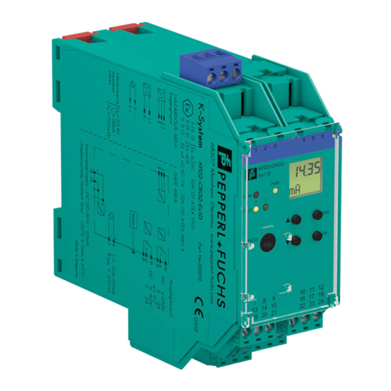
Universal Transmitter Power Supply KF**-CRG2-(Ex)1.D Overview The K-System Universal Transmitter Power Supply KF**-CRG2-(Ex)1.D converts a fully parameterizable partition of input signal in a proportional output current (4 mA to 20 mA). This output signal will be transferred to indicators or to analogue inputs on the process control system/control system, for example. -
Page 7: Safety Instructions
If faults cannot be eliminated, the devices must be taken out of operation and protected from being placed in service again inadvertently. Devices must only be repaired directly by the manufacturer Pepperl+Fuchs. Tampering with or making changes to the devices is dangerous and therefore not permitted. They render the warranty void. -
Page 8: Explosion Protection
(water, small foreign objects). Attention The devices of the K-system from Pepperl+Fuchs and thus also the Universal Transmitter Power-Supply KF**-CRG2-(Ex)1.D can be mounted on a 35 mm DIN mounting rail according to DIN EN 60715. The devices must be snapped onto the rail vertically, and never slanted or tipped to the side. -
Page 9: Connection
Universal Transmitter Power Supply KF**-CRG2-(Ex)1.D Installation and Connection Dimensions of the device in mm 40 mm (1.6") 115 mm (4.5'') Connection The removable terminals considerably simplify the connection and the switch cabinet assembly. They make it possible to replace devices quickly and without error if a customer service becomes necessary. -
Page 10: Connection Input (Field Circuit)
Universal Transmitter Power Supply KF**-CRG2-(Ex)1.D Installation and Connection 5.2.1 Connection Input (Field Circuit) The intrinsically safe field circuit is connected to the blue terminals 1 to 3 on the KF**-CRG2-Ex1.D. This may be conducted using DIN EN 60079-14-compliant leads into the hazardous area. The non-intrinsically safe field circuit is connected to the green terminals 1 to 3 on the KF**-CRG2-1.D. -
Page 11: Connection Output
Universal Transmitter Power Supply KF**-CRG2-(Ex)1.D Installation and Connection 5.2.2 Connection Output The control circuit and the power supply are connected to the green terminals 7 to 24 on the device. The terminals have the following functions: • Terminals 7/8: current output (terminal 9 not used) •... -
Page 12: Field Device Communication Via Hart
Universal Transmitter Power Supply KF**-CRG2-(Ex)1.D Installation and Connection Field Device Communication via HART In order to set the parameters of the connected HART field device, you will require a HART communicator which you can connect to the field cables. Transmitting the HART signal via the current output of the device is not possible. -
Page 13: Display Modes And Fault Messages
For the selection of error messages see section 7.3.1. If switching the device on/off and checking the cables does not rectify the fault, please contact Pepperl+Fuchs or the field device manufacturer. The relays de-energizes when a fault occurs. For information on the behaviour of the current output in the event of fault, see section 7.5.2. -
Page 14: Editing Device Data
In this manual, the parameterisation of the device via the control panel is described. Parameterisation by means of a PC is more convenient. The necessary K-ADP-USB can be ordered from Pepperl+Fuchs. The PACTware operating software and the manual are available on our Internet page Note www.pepperl-fuchs.com under Software >... -
Page 15: Password
Universal Transmitter Power Supply KF**-CRG2-(Ex)1.D Editing Device Data: Parameterization Mode 7.1.2 Password You can protect the parameterization from unauthorized changes by means of a password (see section 7.6; at the delivery of the device, the password is inactive). If the password protection is active, you can view the different settings in the parameterization mode, but not change them before entering the password. -
Page 16: Navigation Method
Universal Transmitter Power Supply KF**-CRG2-(Ex)1.D Editing Device Data: Parameterization Mode 7.1.3 Navigation Method The following diagram shows the navigation method in parameterization mode using the , , OK and ESC keys: OK Rel1 Min/Max Trip ... -
Page 17: Lowest Menu Level: Select Values, Enter Numeric Values
Universal Transmitter Power Supply KF**-CRG2-(Ex)1.D Editing Device Data: Parameterization Mode 7.1.4 Lowest Menu Level: Select Values, Enter Numeric Values On the lowest level of the menu, you can either select one of several possible values, or enter a number for the individual parameters. Proceed as follows: Lowest menu level OK ... -
Page 18: Unit
Universal Transmitter Power Supply KF**-CRG2-(Ex)1.D Editing Device Data: Unit Unit The following diagram shows the unit menu. Items from the lowest menu level are outlined in bold. The device measures in mA. Using the parameters zero point and conversion factor (section 7.3.2) it converts the measured value into the selected units. -
Page 19: Input
Universal Transmitter Power Supply KF**-CRG2-(Ex)1.D Editing Device Data: Input Input The following diagram shows the input parameters menu. Items from the lowest menu level are outlined in bold. The menu items Zero point and Conversion factor will not be shown if the unit mA is selected (section 7.2). -
Page 20: Line Monitor
Universal Transmitter Power Supply KF**-CRG2-(Ex)1.D Editing Device Data: Input 7.3.1 Line Monitor • If you select On for LB, an input current < 0.2 mA will be registered as a lead break (section 6). • If you select On for SC, an input current > 22 mA will be registered as a short circuit (section 6). If you wish to process the ... - Page 21 Universal Transmitter Power Supply KF**-CRG2-(Ex)1.D Editing Device Data: Input Example 1: selected unit °C, 0 °C to 200 °C is to correspond to 4 mA to 20 mA y [°C] x [mA] 9 10 11 12 13 14 15 16 17 18 19 20 -100 -150 -200...
- Page 22 Universal Transmitter Power Supply KF**-CRG2-(Ex)1.D Editing Device Data: Input Example 2: selected unit °C, 0 °C to -100 °C is to correspond to 20 mA to 0 mA y [°C] 9 10 11 12 13 14 15 16 17 18 19 20 x [mA] -100 -150...
- Page 23 Universal Transmitter Power Supply KF**-CRG2-(Ex)1.D Editing Device Data: Input Example 3: selected unit bar, -4 bar to 4 bar is to correspond to 4 mA to 20 mA y [bar] x [mA] 9 10 11 12 13 14 15 16 17 18 19 20 •...
-
Page 24: Linerization
Universal Transmitter Power Supply KF**-CRG2-(Ex)1.D Editing Device Data: Input 7.3.3 Linerization Using the parameterization software PACT a linearization table can be saved in the device; for ware details of this function see On-line help. Via the operator panel you can merely switch the use of the table for the calculation of the output value on and off (On/Off). -
Page 25: Relays
Universal Transmitter Power Supply KF**-CRG2-(Ex)1.D Editing Device Data: Relays Relays The following diagram shows the relay outputs menu. Items from the lowest menu level are outlined in bold. From the Rel1 and Rel2 menu options, you can use the OK key to get to a menu in which you can enter individual parameters for the selected relay. -
Page 26: Operating Behaviour
Universal Transmitter Power Supply KF**-CRG2-(Ex)1.D Editing Device Data: Relays Alarm freeze (7.4.3) —— Delay (7.4.4) —— 0 s to 250 s 7.4.1 Operating Behaviour The switching direction can be set as Max or Min and the direction of action as Active or Passive (section 7.4). - Page 27 Universal Transmitter Power Supply KF**-CRG2-(Ex)1.D Editing Device Data: Relays The exact operating behaviour of the device is shown in the following diagram: Value Max – hysteresis Min + hysteresis Time Switching direction Max, mode of operation Active: energized de-energized Switching direction Max, mode of operation Passive: energized de-energized Switching direction Min, mode of operation Active:...
-
Page 28: Trip And Hysteresis
Universal Transmitter Power Supply KF**-CRG2-(Ex)1.D Editing Device Data: Relays 7.4.2 Trip and Hysteresis When entering the values for Trip and Hysteresis please note: • Both values are to be entered in the units, which were selected under Units (section 7.2). •... - Page 29 Universal Transmitter Power Supply KF**-CRG2-(Ex)1.D Editing Device Data: Relays The following diagram shows the operating behaviour for the trip mode Max, operating mode Active. Value Trip point Max Max – hysteresis Time Switching direction Max, mode of operation Active, with delay energized de-energized Delay...
-
Page 30: Current Output
Universal Transmitter Power Supply KF**-CRG2-(Ex)1.D Editing Device Data: Current Output Current Output The following illustrations show the current output menus. Items from the lowest menu level are outlined in bold. Information about relay outputs see section 7.4. Output —— Rel1 Rel2 Iout ——... -
Page 31: Characteristic
Universal Transmitter Power Supply KF**-CRG2-(Ex)1.D Editing Device Data: Current Output Start value —— 7.5.3 End value —— 7.5.3 Inverted (7.5.1) —— Inverted Normal 7.5.1 Characteristic With the parameters Start value and End value establish a sub-range of the input signal as the measuring range of the application (section 7.5.3). - Page 32 Universal Transmitter Power Supply KF**-CRG2-(Ex)1.D Editing Device Data: Current Output Characteristic Start value End value Linear Linear overrange converted into converted into underrange up to up to 0 mA to 20 mA 0 mA 20 mA 0 mA 20.5 mA 4 mA to 20 mA 4 mA 20 mA...
-
Page 33: Fault Current
Universal Transmitter Power Supply KF**-CRG2-(Ex)1.D Editing Device Data: Current Output 7.5.2 Fault Current The following table shows the current output in the event of a fault, depending on the characteristic. Setting 0 mA to 20 mA 4 mA to 20 mA NE43 4 mA to 20 mA Up/Down 21.5 mA... -
Page 34: Service
Universal Transmitter Power Supply KF**-CRG2-(Ex)1.D Editing Device Data: Service Service The following diagram shows the service parameter menus. Items from the lowest menu level are outlined in bold. Service —— Password (7.1.2) —— Language —— DE (German) ENG (English) Reset (see below) ——... -
Page 35: Default Settings
Universal Transmitter Power Supply KF**-CRG2-(Ex)1.D Editing Device Data: Default Settings Default Settings Menu Parameter Default setting Separate value Main menu Unit Input Line monitor On LB/On SC Zero point 4.000 mA Conversion factor 0.100 Linearization Smoothing Output Rel1 Min/Max (= switching direction) Trip 16.00 mA Hysteresis... - Page 36 Universal Transmitter Power Supply KF**-CRG2-(Ex)1.D Editing Device Data: Default Settings Menu Parameter Default setting Separate value Fault current Start value 0.000 mA End value 20.00 mA Inverted Normal Service Password Language...
- Page 37 Universal Transmitter Power Supply KF**-CRG2-(Ex)1.D Notes...
- Page 38 PROCESS AUTOMATION – PROTECTING YOUR PROCESS Worldwide Headquarters Pepperl+Fuchs GmbH 68307 Mannheim · Germany Tel. +49 621 776-0 E-Mail: info@de.pepperl-fuchs.com For the Pepperl+Fuchs representative closest to you check www.pepperl-fuchs.com/contact www.pepperl-fuchs.com 70101417 DOCT-1496F Subject to modifications Copyright PEPPERL+FUCHS · Printed in Germany 12/2018...
Need help?
Do you have a question about the KF**-CRG2-Ex1.D Series and is the answer not in the manual?
Questions and answers