Advertisement
Quick Links
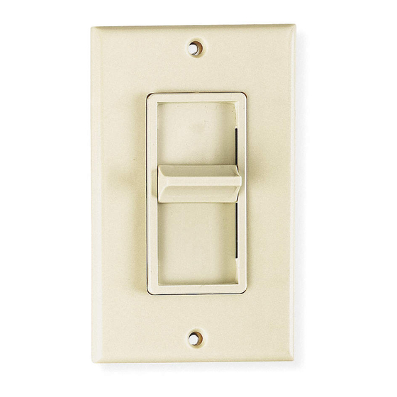
C O L L E C T I O N B Y L E V I T O N
Single Pole (1 location)
120VAC, 60Hz
Slide Fan Speed Control
Cat. No. 6627, 4A
INSTALLATION INSTRUCTIONS
Unipolaire (1 emplacement)
120 V c. a., 60 Hz
Commande à glissière
de vitesse de ventilateur
Nº de cat. 6627, 4 A
DIRECTIVES D'INSTALLATION
Unipolar (1 ubicación)
120VCA, 60Hz
Control Deslizante
p/Velocidad de Ventilador
No. de Cat. 6627, 4A
INSTRUCCIONES DE INSTALACION
DI-70x-06627-20A
LIMITED 2 YEAR WARRANTY AND EXCLUSIONS
Leviton warrants to the original consumer purchaser and
not for the benefit of anyone else that this product at the
time of its sale by Leviton is free of defects in materials
and workmanship under normal and proper use for two
years from the purchase date. Leviton's only obligation is
to correct such defects by repair or replacement, at its
option, if within such two year period the product is returned
prepaid, with proof of purchase date, and a description of
the problem to Leviton Manufacturing Co., Inc., Att:
Quality Assurance Department, 59-25 Little Neck
Parkway, Little Neck, New York 11362-2591. This warranty
excludes and there is disclaimed liability for labor for
removal of this product or reinstallation. This warranty is
void if this product is installed improperly or in an improper
environment, overloaded, misused, opened, abused, or
altered in any manner, or is not used under normal
operating conditions or not in accordance with any labels
or instructions. There are no other or implied warranties of
any kind, including merchantability and fitness for a
particular purpose, but if any implied warranty is required
by the applicable jurisdiction, the duration of any such
implied warranty, including merchantability and fitness for
a particular purpose, is limited to two years. Leviton is not
liable for incidental, indirect, special, or consequential
damages, including without limitation, damage to, or loss
of use of, any equipment, lost sales or profits or delay or
failure to perform this warranty obligation. The remedies
provided herein are the exclusive remedies under this
warranty, whether based on contract, tort or otherwise.
For Technical Assistance Call:
1-800-824-3005 (U.S.A. Only)
www.leviton.com
DI-70x-06627-20A
DI-70x-06627-20A
1
English
FEATURES
• Leviton's Decora
®
style design
• Slide control for easy and precise operation
• Operates any number of ceiling fans up to rating limits
• Minimum Speed Adjustment
• Fits standard wall boxes
INSTALLATION INSTRUCTIONS
WARNING:
TO BE INSTALLED AND/OR USED IN ACCORDANCE WITH APPROPRIATE ELECTRICAL CODES
AND REGULATIONS.
WARNING:
IF YOU ARE NOT SURE ABOUT ANY PART OF THESE INSTRUCTIONS, CONSULT A QUALIFIED
ELECTRICIAN.
WARNING:
TO AVOID OVERHEATING AND POSSIBLE DAMAGE TO THIS DEVICE AND OTHER EQUIPMENT,
DO NOT INSTALL TO CONTROL A RECEPTACLE, FLUORESCENT LIGHTING, A MOTOR- OR A
TRANSFORMER-OPERATED APPLIANCE OTHER THAN APPROPRIATE CEILING FANS.
WARNING:
TO REDUCE THE RISK OF FIRE OR ELECTRICAL SHOCK, THIS CONTROL IS TO BE USED
WITH A CEILING FAN THAT IS MARKED AS SUITABLE FOR USE WITH A SOLID-STATE FAN SPEED
CONTROL AND IS RATED 120 VOLTS, 4 AMPERES MAXIMUM.
WARNING:
FOR USE ON CEILING PADDLE FANS WITH SPLIT-CAPACITOR OR SHADED POLE MOTORS
ONLY. PLEASE REFER TO FAN MANUFACTURER'S INSTRUCTIONS OR RATING LABELS ON THE MOTOR TO
CONFIRM TYPE. USE WITH ANY OTHER TYPES OF MOTORS OR EQUIPMENT MAY CAUSE OVERHEATING
AND/OR DAMAGE TO THE MOTORS OR EQUIPMENT.
OTHER CAUTIONS:
1. DISCONNECT POWER WHEN SERVICING FIXTURE.
2. USE THIS DEVICE ONLY WITH COPPER OR COPPER CLAD WIRE. WITH ALUMINUM WIRE USE ONLY
DEVICES MARKED CO/ALR OR CU/AL.
MULTI-FAN CONTROL:
Any number of fans of the same type may be controlled by a single fan speed control provided that the total
amperage of the fans does not exceed the amperage rating of the fan speed control.
GANGING/DERATING:
When combinations of dimming and/or speed controls are installed in a ganged wall or outlet box, derating is
required. When two devices are mounted in a ganged box, the maximum load per device shall not exceed 4A or
500 watts. When three or more devices are mounted in a ganged box, the maximum load shall not exceed 3A or
400 watts.
TO INSTALL:
1.
WARNING:
TO AVOID FIRE, SHOCK, OR DEATH; TURN OFF POWER AT CIRCUIT BREAKER OR FUSE
AND TEST THAT POWER IS OFF BEFORE WIRING!
2. Remove existing wallplate and switch, if applicable.
3. Remove 3/4" (1.9 cm) of insulation from each circuit conductor. Make sure the ends of wires are straight.
4. Connect wires per WIRING DIAGRAM as follows: Twist strands of each lead tightly together and, with circuit
conductors, push firmly into appropriate wire connector. Screw connectors on clockwise making sure no bare
conductors show below the wire connectors. Secure each connector with electrical tape.
5. Restore power at circuit breaker or fuse. Holding speed control securely by its insulated case, make sure fan is
rotating by moving ON/OFF rocker switch to ON position and sliding control lever to a middle position.
6. Interrupt power by moving ON/OFF rocker switch to OFF position. Slide control bar DOWN to lowest position
(closest to ON/OFF rocker switch).
7. After fan stops rotating, restore power by moving ON/OFF rocker switch to ON position (keep control bar down
at lowest position). Fan should rotate at low end speed after power has been restored. If fan blades are not
rotating, adjust low end (slowest) fan speed as follows:
A. Insert a small screwdriver into trim slot.
B. Turn clockwise to increase fan speed, counterclockwise to lower fan speed. The low end trim is now set.
8. TURN OFF POWER. Installation may now be completed by carefully positioning all wires to provide room in
outlet box for fan speed control. Mount fan speed control into box with mounting screws supplied. Attach
wallplate.
9. Restore power at circuit breaker or fuse. INSTALLATION IS COMPLETE.
OPERATION
Slide bar control up or down for desired fan rotation speed. ON/OFF rocker switch will turn fan ON at speed set by
slide bar.
Français
CARACTÉRISTIQUES
• Style de la gamme Decora
MD
de Leviton
• Commande à glissière pour un réglage simple et précis
• Compatibilité à de nombreux modèles de ventilateurs dans les limites prescrites
• Réglage de la vitesse minimale
• S'adapte à toute boîte simple standard
DIRECTIVES D'INSTALLATION
AVERTISSEMENT :
INSTALLER OU UTILISER CONFORMÉMENT AUX CODES DE L'ÉLECTRICITÉ EN
VIGUEUR.
AVERTISSEMENT :
À DÉFAUT DE BIEN COMPRENDRE LES DIRECTIVES SUIVANTES, FAIRE APPEL À UN
ÉLECTRICIEN QUALIFIÉ.
AVERTISSEMENT :
POUR ÉVITER LA SURCHAUFFE OU L'ENDOMMAGEMENT ÉVENTUEL DE CE
DISPOSITIF ET D'AUTRES APPAREILS RACCORDÉS, NE PAS L'INSTALLER POUR COMMANDER UNE PRISE,
UN LUMINAIRE FLUORESCENT, OU UN APPAREIL MOTORISÉ OU À TRANSFORMATEUR AUTRE QU'UN
VENTILATEUR POUR PLAFOND APPROPRIÉ
AVERTISSEMENT :
POUR RÉDUIRE LES RISQUES D'INCENDIE OU DE CHOC ÉLECTRIQUE, N'UTILISER
CE DISPOSITIF NE DOIT ÊTRE UTILISÉ QUE POUR LES VENTILATEURS DE PLAFOND IDENTIFIÉS COMME
ÉTANT CONÇUS POUR PERMETTRE UNE RÉGULATION DE LES VITESSE ET DOIVENT AUSSI AVOIR DES
VALEURS NOMINALES MAXIMALES DE 120 VOLTS C.A., 4 AMPÈRES.
AVERTISSEMENT :
NE PEUT ÊTRE UTILISÉ QU'AVEC DES MOTEURS À CONDENSATEUR OU À BAGUE
DE DÉPHASAGE; VEUILLEZ CONSULTER LES DIRECTIVES DU FABRICANT DE VENTILATEURS, OU
L'ÉTIQUETTE SIGNALÉTIQUE APPOSÉE SUE LE MOTEUR, POUR EN CONFIRMER LE TYPE; UNE
UTILISATION AVEC TOUT AUTRE TYPE DE MOTEUR OU D'APPAREIL POURRAIT CAUSER LA SURCHAUFFE,
VOIRE MÊME LE BRIS, DE CE MOTEUR OU DE CET APPAREIL.
AUTRES MISES EN GARDE :
1. LORS D'UNE VÉRIFICATION D'APPAREILS, COUPER L'ALIMENTATION.
2. N'UTILISER CE DISPOSITIF QU'AVEC DU FIL DE CUIVRÉ; EN PRÉSENCE DE FIL D'ALUMINIUM, UTILISER
SEULEMENT LES DISPOSITIFS PORTANT LA MARQUE CO/ALR OU CU/AL.
COMMANDE DE PLUSIEURS VENTILATEURS : un seul dispositif peut commander plusieurs ventilateurs, à
condition que la puissance totale de ces derniers ne dépasse pas les valeurs nominales de la commande.
GROUPEMENT/ABAISSEMENT : lorsque des commandes de gradation de lumière ou de vitesse sont combinées,
on doit opérer un certain déclassement; quand deux unités sont combinées, la charge maximale par unité ne
devra pas excéder 4 A ou 500 W.; quand plus de deux unités sont combinées, cette charge ne devra jamais
dépasser 3 A ou 400 W.
INSTALLATION :
AVERTISSEMENT :
1.
POUR ÉVITER LES RISQUES D'INCENDIE, DE CHOC ÉLECTRIQUE OU DE
BLESSURE MORTELLE, COUPER LE COURANT AU FUSIBLE OU AU DISJONCTEUR ET S'ASSURER QUE
LE CIRCUIT SOIT BIEN COUPÉ AVANT DE PROCÉDER À L'INSTALLATION.
2. Retirer la plaque murale et l'interrupteur existant, le cas échéant.
3. Dénuder l'extrémité de chaque fil du circuit afin d'exposer 1,9 cm (3/4 po) de cuivre; s'assurer que les brins
soient bien droits.
4. Raccorder les fils conformément au SCHÉMA DE CÂBLAGE et de la façon suivante : entortiller fermement les
brins de chaque fil et les enfoncer, avec le conducteur de circuit approprié, dans des serre-fils de format
convenable; tourner ces derniers vers la droite en s'assurant qu'aucun brin ne dépasse; protéger les raccords
au moyen de ruban isolant.
5. Rétablir le courant au fusible ou au disjoncteur; en ayant bien soin de tenir le boîtier du commande de façon
sécuritaire, assurez-vous du bon fonctionnement du ventilateur en plaçant l'interrupteur MARCHE/ARRÊT à
bascule à la position «ON» et le régulateur à glissière en position centrale.
6. Arrêtez le ventilateur en mettant l'interrupteur MARCHE/ARRÊT à bascule à la position «OFF»; places le
régulateur à la position plus basse, soit le plus près possible de l'interrupteur MARCHE/ARRÊT à bascule.
7. Lorsque ses pales ne tourneront plus, faites redémarrer le ventilateur en mettant l'interrupteur
MARCHE/ARRÊT à bascule à la position «ON» (laissez le régulateur à la position plus basse); le ventilateur
devrait alors tourner ¡a sa plus basse vitesse; si les pales ne tournent pas, réglez la vitesse minimale du
ventilateur comme suit:
A. Insérer un petit tournevis dans la fente de réglage.
B. Tourner dans le sens de aiguilles d'une montre pour augmenter la vitesse, el dans le sens contraire pour la
réduire; la vitesse de l'appareil devrait être réglée au plus bas.
5/16/02, 3:05 PM
Advertisement

Related Manuals for Leviton DECORA SURESLIDE 6627


Summary of Contents for Leviton DECORA SURESLIDE 6627
- Page 1 TO INSTALL: INSTALLATION : time of its sale by Leviton is free of defects in materials WARNING: TO AVOID FIRE, SHOCK, OR DEATH; TURN OFF POWER AT CIRCUIT BREAKER OR FUSE...
- Page 2 PARA USARSE SOLO EN VENTILADORES DE PALETA PARA TECHO CON MOTORES DE POLOS PROTEGIDOS O DE CAPACITOR DIVIDIDO. FAVOR de 2 ans suivant la date d’achat. La seule obligation de Leviton sera de corriger les dits défauts en réparant ou en remplaçant le produit défectueux si ce dernier est retourné...
Need help?
Do you have a question about the DECORA SURESLIDE 6627 and is the answer not in the manual?
Questions and answers