
Subscribe to Our Youtube Channel
Related Manuals for Leviton MC7008


Summary of Contents for Leviton MC7008
-
Page 1: User Guide
MC 7008 MC 7016 MC 7024 MC 7008 / MC 7016 / MC 7024 MEMORY LIGHTING CONTROLLERS USER GUIDE Software Revision 1.00 and above Document Revised: 8-30-02 Copyright 1994, 2002 Leviton Manufacturing Co., Inc. Page 1 PK-93130-00-01-1A... -
Page 2: Table Of Contents
Introduction ... 3 Welcome ... 3 Specifications ... 3 Installation/Setup ... 3 Power Supply Requirements ... 3 Dimmer Equipment Connection ... 4 Overview ... 4 Front Panel ... 4 Rear Panel ... 5 Operation Guide ... 6 General ... 6 Operation Modes ... -
Page 3: Introduction
Up to 128 individual control signals may be transmitted to dimmer packs through a single microphone cable and the returned phantom power eliminates the need for AC power cords on Leviton-NSI controllers. This makes the remote placement of the MC 7000 Series Lighting Console easy and convenient. -
Page 4: Dimmer Equipment Connection
Dimmer Equipment Connection Connecting the MC 7000 Series Lighting Console to Leviton-NSI dimming equipment is very simple. You need only connect a single 3 conductor audio cable (standard microphone cable equipped with a 3- pin XLR type connector) to either of the jacks marked MICROPLEX on the rear apron of the console. It doesn’t matter which jack is used, two jacks are provided for convenience. -
Page 5: Rear Panel
Blackout whenever the Blackout LED is lit. Rear Panel 1. Microplex Outputs: These 2 outputs provide Leviton-NSI’s microphone dimmer connection via a 3-pin XLR type connector. Either connector may be used (1-Male, 1-Female). 2. DMX512: This optional output is used to provide dimmer control information to dimmers using this protocol. -
Page 6: Operation Guide
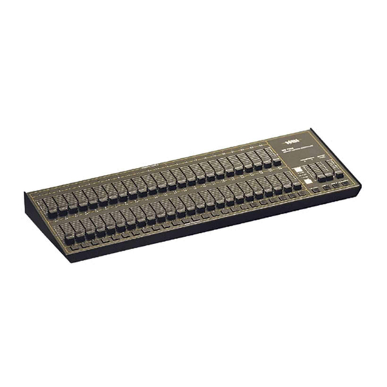
General The MC 7000 Series Lighting Console consists of two manual scenes mastered by two split/dipless crossfaders, a set of bump buttons, two programmable chase effects, a master control and a blackout button. The console is designed to allow tailoring to your needs. Three modes of operation vary the function of the Bump buttons from individual Channel Bumps to Flash Scenes, and Scene Y from channels 1 - 8 (1 - 16) [1 - 24], to channels 9 –16 (17 - 32) [25 - 48], or to Memory Scene Masters. -
Page 7: Bump Buttons
Bump Buttons Along the bottom edge of the console are 8 (16) [24] momentary push buttons. These buttons are used to bump each individual channel to full intensity regardless of the Blackout button or the setting of the Master control. When in the 1 x 16 (1 x 32) [1 x 48] mode, each button no longer controls only one channel, but can be programmed to control any combination of channels. -
Page 8: Programming Control Functions
PROGRAMMING CONTROL FUNCTIONS General The functions that can be programmed on the MC 7000 Series Lighting Console are the two Chases, the Scene Masters in the 8 x 8 (16 x 16) [24 x 24] mode and the Flash Scenes in the 1 x 16 (1 x 32) [1 x 48] mode. -
Page 9: Chases
Chases Each of the two Chase functions can be programmed to include any channel in any step up to a maximum of 32 steps per Chase. To initiate Chase programming, first tap the Program button so that the Program LED is lit. Then tap the Chase button of the Chase to be programmed and the LED under the chase button should start flashing. -
Page 10: Optional Dmx512 Installation
EXAMPLE: Program a 4-step chase consisting of channels 17 - 20 into Chase 1 of a MC 7016. 1. Tap the Mode button until the LED next to 1 x 32 is lit. 2. Tap the Program button. The Program LED should now be lit. 3. -
Page 11: Troubleshooting
Symptom Channel Level LED’s do not respond. Chase functions do not work. Lights on stage do not operate even though Channel Level LED’s do. Scene X or Scene Y slide controls have no effect on channel levels. Stage lights are ON, but will not respond or respond erratically. - Page 12 Leviton warrants to the original consumer purchaser and not for the benefit of anyone else that this product at the time of its sale by Leviton is free of defects in materials and workmanship under normal and proper use for two years from the purchase date.
Need help?
Do you have a question about the MC7008 and is the answer not in the manual?
Questions and answers