Table of Contents
Advertisement
Quick Links
• Leviton's Decora
C O L L E C T I O N B Y L E V I T O N
• Low-Voltage for easy installation
• Fits standard wall box
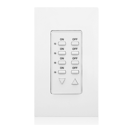
DALI Controller
The DALI Controller, Cat No. CD250, allows easy control of fluorescent ballasts supporting the DALI (Digital Addressable
(Multi-Location)
Lighting Interface) specification. The DALI controller provides a cost-effective and easy way to control individual ballasts, a
group of ballasts, or call scenes. There are two types of operations of the CD250, which are Non-Scene and Scene Control.
Cat. No. CD250
Within these operations, there are several modes which allow the user great flexibility in how the CD250 is used. The CD250
comes installed with an individual/group controller face and a scene controller face change kit is included.
16VDC
The DALI Controller has a user-friendly interface. The DALI Controller has two Operations: Non-Scene and Scene operation.
Input Current:
Within the Non-Scene Operation, there are the non-scene individual and non-scene group modes. The non-scene individual
ON/OFF mode offers control of up to 4 separate DALI compatible ballasts. In this mode, the DALI controller can DIM/BRIGHT
11mA max., less than 1W
up to 4 individual ballasts. On a DALI Network, the user can control up to a maximum of 64 individual ballasts using multiple
DALI controllers (CD250). For example, if one controller controls ballasts 1-4, a second CD250 controller can be added and
For use w/DALI Loop Power Pack
programmed to control ballasts 5-8.
When in non-scene group mode, the controller controls up to 4 programmed groups of DALI compatible ballasts. In that group
mode, the DALI controller provides ON/OFF and DIM/BRIGHT control for up to 16 groups of DALI compatible ballasts.
In Scene operation, the user has the option of either being able to control the DALI compatible ballasts under the scene
INSTALLATION INSTRUCTIONS
individual, scene group, or scene broadcast modes. When in scene individual mode, the controller calls programmed "presets"
for a single ballast. When in scene group mode, the controller calls "preset" light levels for a group of ballasts. In scene
broadcast mode, the DALI controller calls presets for ALL ballasts on that DALI network.
The DALI Controller has a removable face to represent the Operation the controller is in. To determine the mode the controller
is in, the user must enter the Programming sequence. The programming sequences for the various modes are described under
DI-000-CD250-00A
the "PROGRAMMING" section.
This device complies with part 15 of the FCC Rules. Operation is subject to the following two conditions: (1) This device must
not cause harmful interference, and (2) This device must accept any interference received, including interference that may
cause undesired operation.
WARNING:
REGULATIONS.
WARNING:
ELECTRICIAN.
CAUTION:
CAUTION:
REPLACING A LIGHT SWITCH. CONSULT LOCAL BUILDING CODES AND REGULATIONS FOR PROPER LOW-VOLTAGE
INSTALLATION.
THE CD250 CAN BE WIRED EITHER AS A CLASS I OR CLASS II WIRING DEVICE. BE SURE TO INSTALL IN THE SAME
MANNER AS THE OTHER DEVICES ON THE DALI LOOP. WHEN IN DOUBT, INSTALL AS A CLASS I WIRING DEVICE.
TO INSTALL:
WARNING:
1.
THAT POWER IS OFF BEFORE WIRING!
2. Remove existing wallplate and switch or dimmer, if applicable.
CAUTION:
WIRE CONNECTORS AND REMOVED FROM WALL BOX.
3. Connect as per WIRING DIAGRAM. Twist strands of each lead tightly and, with DALI loop wires, push firmly into appropriate
wire connector. Screw connectors on clockwise making sure that no bare conductor shows below the wire connectors.
Secure each connector with electrical tape.
NOTE: The DALI leads are polarity insensitive.
LIMITED 2 YEAR WARRANTY AND EXCLUSIONS
4. Carefully position all wires to provide room in outlet box for DALI controller. Mount DALI controller into box with mounting
screws supplied.
Leviton warrants to the original consumer purchaser and not
for the benefit of anyone else that this product at the time of
5. Restore power at circuit breaker or fuse. INSTALLATION IS COMPLETE.
its sale by Leviton is free of defects in materials and
workmanship under normal and proper use for two years from
the purchase date. Leviton's only obligation is to correct such
The face of this device can be changed to represent the mode the DALI controller is in. Simply replace the ON/OFF face with
defects by repair or replacement, at its option, if within such
the scene face on the DALI controller, which is included with the controller (please note that wallplate must be removed).
two year period the product is returned prepaid, with proof of
purchase date, and a description of the problem to Leviton
1. Select the face of the mode you desire.
Manufacturing Co., Inc., Att: Quality Assurance
2. The frame has snaps on its sides. Using a small screwdriver, gently remove the frame from the strap (refer to Figure 7).
Department, 59-25 Little Neck Parkway, Little Neck, New
3. Take the new frame and position it properly to the strap. Orient the frame so that the ON button/Scene 1 (depending on
York 11362-2591. This warranty excludes and there is
which face is installed) is the top button. Line up the plastic snaps with the square holes in the strap. Insert the snaps on one
disclaimed liability for labor for removal of this product or
reinstallation. This warranty is void if this product is installed
side of the frame into the strap.
improperly or in an improper environment, overloaded,
4. Firmly press sideways and down to slip the other snaps into place. The frame snaps in with an audible click. Ensure that all
misused, opened, abused, or altered in any manner, or is
four snaps are secure. Replace Decora
not used under normal operating conditions or not in
accordance with any labels or instructions. There are no other
or implied warranties of any kind, including merchantability
and fitness for a particular purpose, but if any implied warranty
DALI CONTROLLER OPERATION:
is required by the applicable jurisdiction, the duration of any
The functioning of the DALI controller is broken up into two major sections representing the two Operations namely, Scene and
such implied warranty, including merchantability and fitness
Non-scene within which there are: Individual mode, Group Mode, and Broadcast Mode. Refer to Figure 1 for an illustration.
for a particular purpose, is limited to two years. Leviton is not
A. Non-Scene Operation:
liable for incidental, indirect, special, or consequential
1. Individual Mode: In this mode, the four rows of buttons control four individual ballasts, providing ON/OFF control.
damages, including without limitation, damage to, or loss of
use of, any equipment, lost sales or profits or delay or failure
Dimming or brightening will only affect one ballast at a time. The DIM/BRIGHT buttons will DIM or BRIGHTEN the last
to perform this warranty obligation. The remedies provided
selected ballast. To BRIGHT/DIM another ballast, you must press the button for that row to "activate" that ballast. If
herein are the exclusive remedies under this warranty,
control of the same ballast is desired with two different controllers, the corresponding button for that ballast from the
whether based on contract, tort or otherwise.
second controller needs to be pressed "ON" before Bright/Dim functionality can be used.
Each row corresponds to a specific address, starting from a base address, which is programmed in the program mode.
For Technical Assistance Call:
The address of each row is sequential, starting from the programmed base address. One controller can control only up to
1-800-824-3005 (U.S.A. Only)
four individual ballasts. If control of more than 4 ballasts is required, multiple controllers are needed, with each controller
www.leviton.com
programmed to a different base address. Refer to Table 1A and 1B for details.
2. Group Mode: In this mode, the four rows of buttons control four individual groups, providing ON/OFF control for the
entire group of ballasts. The DIM/BRIGHT buttons will DIM or BRIGHTEN the last selected group. Dimming or brightening
will only affect one group at a time. Each row corresponds to a specific group number, starting from a base group
DI-000-CD250-00A
FEATURES
®
Style design
• One device offers individual, group, and scene control for DALI
dimmable ballasts
• Scene controller conversion face included
• Multiple controllers can easily be added to the DALI network
INTRODUCTION
DESCRIPTION
FCC COMPLIANCE STATEMENT
INSTALLATION INSTRUCTIONS
TO BE INSTALLED AND/OR USED IN ACCORDANCE WITH APPROPRIATE ELECTRICAL CODES AND
IF YOU ARE NOT SURE ABOUT ANY PART OF THESE INSTRUCTIONS, CONSULT A QUALIFIED
DISCONNECT POWER WHEN SERVICING FIXTURE OR CHANGING LAMPS.
THE DALI CONTROLLER OPERATES OFF OF LOW-VOLTAGE (16VDC), SO CARE MUST BE TAKEN WHEN
TO AVOID FIRE, SHOCK, OR DEATH; TURN OFF POWER AT CIRCUIT BREAKER OR FUSE AND TEST
IF APPLICABLE, ENSURE THAT UNUSED CIRCUIT CONDUCTORS ARE PROPERLY CAPPED OFF WITH
FACE CONVERSION PROCEDURE
®
wallplate. The face conversion is complete.
TO OPERATE
number, which is programmed in the program mode. The group number of each row is sequential, starting from the
programmed base group number. If multiple controllers are used to control more than 4 ballasts, then each controller
must be programmed to a different base group number. Refer to Table 1A and 1B for details.
NOTES:
• The LED next to each button will light when that button is pressed, indicating the last action taken. When mixing
individual controls with group controls and scene controls on the same DALI loop, the ON/OFF LED indicators may not
represent the actual state of the lights.
• When turning on individual ballast or a group, the lights will turn ON to maximum.
B. Scene Operation:
Scene Mode: In scene mode, each button calls a specific scene. The scene face on the controller shows scenes 1-7, and
Off. The Off scene is displayed on the controller face as a convenience. The default state of all scenes is un-programmed,
including Off. All scenes (including Off) must be programmed.
The LED next to each scene button will light when that button is pressed.
1. Scene Mode – Individual: When the CD250 is in the scene mode, and the individual/group selection is set to individual,
the scene controller will call one of 8 presets for the ballast with the same address (short address) as the scene
controller. The individual ballast can be dimmed or brightened using the DIM/BRIGHT buttons.
2. Scene Mode – Group: When the CD250 is in scene mode, and the individual/group selection is set to group, the scene
controller will call a scene [either 1-8 or 9-16 (scenes 8 and 16 need to be programmed Off)], for the group number
programmed. The group can be dimmed or brightened using the DIM/BRIGHT buttons.
3. Scene Mode – Broadcast: When the CD250 is in scene mode, and the individual/group selection is set to group, AND
the Broadcast selection is set, the scene controller will call a
scene for ALL groups. All groups can be dimmed or brightened
Table 1A – Addressing for the CD250
using the DIM/BRIGHT buttons.
ADDRESSING AND GROUP IDS:
The DALI ballasts must be assigned addresses. When programming
the CD250 to work as an individual controller, the ballasts are given
addresses that correspond to the address programmed into the
Controller A
controller. One controller can control up to 4 individual ballasts. To
enable this functionality, the CD250 must be programmed with a base
address. The base address is used by the CD250 to provide 4
sequential addresses, one for each row of buttons. So if the base
Controller B
address is set to 2, the rows correspond to addresses 2,3,4,5 (from
top to bottom).
Non-Scene Individual Mode:
Controller C
When using multiple controllers, the base address of each
controller must be programmed. There are 64 individual ballasts
allowed on the DALI loop. To control 64 individual ballasts from the
CD250, we need to install 16 CD250's (16x4 = 64), and assign a
base address to each controller. This means that the range of
Table 1B – Addressing for the CD250
base addresses is from 0 to 63, and one base address
corresponds to 4 DALI addresses. When programming the base
address, a number from 0 to 63 must be chosen. From a base
address, the CD250 maps rows on each controller to a DALI
address. When the programming procedure is finished, each of
Controller A
the ballasts chosen will have an address that corresponds to a
particular row. Note that it is possible to have the same ballast
controlled by more than one controller depending on what base
address is programmed on the devices (refer to Table 1A).
Controller B
However, the user may opt to address the controllers such that
four ballasts are controlled uniquely by one CD250 device and
choose not to have overlapping functionality. If this is desired,
refer to Table 1A for a description of how base and DALI
Controller C
addressing works in this situation. Note that the DALI addresses
will rollover after reaching address 63. The short address will
rollover to 0 if the base address is such that rollover is forced
(refer to Table 1B).
Non-Scene Group Mode
When controlling groups, it is necessary to provide a group Id.
There are 16 groups available. To control 16 groups from the
CD250, we need to install 4 CD250's, and assign a base group ID
Controller X
to each controller, just like in the case of individual control. The
address rollover works the same way in Group mode as in
Individual mode described above.
PROGRAMMING
There are two types of programming for the CD250. There is MODE and address programming, called program mode A (PMA)
and DALI setup programming, program mode B (PMB). The programming steps are split into separate operations to simplify
programming. PMA is used for programming the MODE of operation and controller base addresses. This is specific to the
CD250. PMB is used for mapping the various buttons on the CD250 to different ballasts, and requires interaction over the DALI
loop with the ballasts.
To enter the program mode, the program button is used in conjunction with the 8 LEDs located near each of the 8 buttons. The
LEDs indicate which of the options are selected, or indicate a binary number relating to an address. Included in this document
are matrices of the LED patterns to ease the programming operation.
Addresses are programmed using binary notation, which represents numbers as 0's and 1's. For the programming of
addresses, the LED status definitions are:
Zero
LED blinking
One
LED continuously lit
The LED definitions for MODE programming will be explained under the appropriate section.
Mode and Address Programming (PMA):
To enter mode and address programming, press and release the program button once. All of the LEDs will flash to indicate
the controller is now in Program Mode A (PMA). The LEDs corresponding to the address and mode bits set to ONE stay on
all the time in this mode. The buttons next to each LED will toggle the state of the LED. The DIM and BRIGHT buttons have
no meaning in this mode.
To terminate program mode A, press the program button while in program mode A.
DALI Setup Programming (PMB):
Pressing and holding the program button for more than 5 seconds will initialize the DALI setup procedure. This procedure is
necessary to address the ballasts and bind them to the certain buttons on the controller. The setup procedure depends on
the mode that has been selected. When this setup mode is entered initially, the row of LEDs will blink sequentially (the
'running' lights) to indicate the DALI setup programming mode. They will then blink each column on and off sequentially.
Individual and Group Control
INDIVIDUAL
MODE
Ballast 1
Ballast 2
Ballast 3
Ballast 4
Base Address/Base
DALI
LED callouts for Non-Scene
Group ID
Address/Group ID
Operation, Individual Mode
0
1
0
2
3
ON
1
2
LED 0
1
3
ON
4
LED 1
2
ON
3
2
LED 2
4
5
ON
LED 3
Base Address/Base
DALI
Group ID
Address/Group ID
0
1
0
2
3
4
LED callouts for Non-Scene
5
1
6
Operation, Group Mode
7
8
9
2
10
ON
11
LED 0
.
.
.
ON
.
.
.
LED 1
.
.
.
ON
LED 2
62
63
ON
62
0
LED 3
1
LED callouts for Scene
Operation, Individual Mode
SCENE 1
LED 0
SCENE 3
LED 1
SCENE 5
LED 2
SCENE 7
LED 3
Figure 1
GROUP
MODE
ON
OFF
Group 1
ON
OFF
Group 2
ON
OFF
Group 3
ON
OFF
Group 4
Figure 2
OFF
LED 4
OFF
LED 5
OFF
LED 6 – Scene
(Flashing)
OFF
LED 7 – Individual/Group
(Flashing)
Figure 3
OFF
LED 4 – N/A
(Flashing)
OFF
LED 5 – N/A
(Flashing)
OFF
LED 6 – Scene
(Flashing)
OFF
LED 7 – Individual/Group
(Lit)
Figure 4
SCENE 2
LED 4 – Scene Bank
(Flashing)
SCENE 4
LED 5 – Broadcast
(Flashing)
SCENE 6
LED 6 – Scene
(Lit)
OFF
LED 7 – Individual/Group
(Flashing)
Advertisement
Table of Contents

Related Manuals for Leviton CD250


Summary of Contents for Leviton CD250
- Page 1 INSTALLATION. THE CD250 CAN BE WIRED EITHER AS A CLASS I OR CLASS II WIRING DEVICE. BE SURE TO INSTALL IN THE SAME MANNER AS THE OTHER DEVICES ON THE DALI LOOP. WHEN IN DOUBT, INSTALL AS A CLASS I WIRING DEVICE.
- Page 2 LED 7 to lit (one) to select non-scene group mode for the device. Refer to Figure 3 for the meaning of the LEDs in PMA, for the case when the CD250 is NOT in scene mode, and used as a group control (LED 6 flashing, LED 7 lit).
Need help?
Do you have a question about the CD250 and is the answer not in the manual?
Questions and answers