Table of Contents
Advertisement
Quick Links
Advertisement
Table of Contents

Related Manuals for RIEJU TANGO 125


Summary of Contents for RIEJU TANGO 125
- Page 1 TANGO TANGO 125 C h a s s i s w o r k s h o p m a n u a l...
- Page 2 Index Chassis INTRODUCTION MANUAL UPDATES SYMBOLOGY USED IN THE MANUAL ABBREVIATIONS USED IN THE MANUAL GENERAL WORK RULES RECOMMENDATIONS TO KNOW THE MOTORCYCLE MAINTENANCE OPERATIONS SPECIFICATIONS AND TECHNICAL CHARACTERISTICS UNPACKING “AESTHETIC” CONTROL IDENTIFICATION DATA SAFETY TAG IDENTIFICATION OF THE MAIN PARTS CONTROLS AND INSTRUMENTS KEYS STEERING LOCK...
- Page 3 Index Chassis DISASSEMBLY 1. SEAT 2. LATERAL COVER 3. FRONT LATERAL COVER 4. PILLION SEAT 5. MUFFLER 6. EXHAUST 7. BATTERY 8. REAR DIRECTION INDICATORS 9. TAILLIGHT 10. AIR FILTER 11. REGULATOR 12. COMPONENTES ELÉCTRICOS 13. CDI UNIT 14. FILTER BOX 15.
- Page 4 Index Chassis 35. REAR FOOTREST 36. REAR BRAKE LEVER 37. DRIVE CHAIN GUARD 38. TRANSMISSION CHAIN 39. REAR BRAKE PUMP 40. KICK-STARTER 41. SWING ARM 42. TORQUE...
- Page 5 Introduction Introduction...
-
Page 6: Manual Updates
N.B.: Rieju, S.A. reserves the right to make changes at any time, without prior notification. For any enquiry, or for further complimentary information, please call the Rieju S.A. After- sales Service. -
Page 7: Symbology Used In The Manual
Introduction Chassis SYMBOLOGY USED IN THE MANUAL CAUTION! Recommendations and precautions regarding rider safety and mo- tor vehicle integrity. WARNING! Situations entailing the risk of personal injury to maintenance or repair mecha- nics, other workshop personnel or third parties, or damage to environment, vehicle or equipment. -
Page 8: Abbreviations Used In The Manual
Introduction Chassis ABBREVIATIONS USED IN THE MANUAL Figure Pr Tr Tightening torque Page Paragraph Section Diagram Table Screw Note: The letter Tr in the illustrations refers to retaining or adjusting screws. The number following this letter refers to the number of the same type of screw in the unit or component described and illustrated. -
Page 9: General Work Rules
Introduction Chassis GENERAL WORK RULES • The advice, recommendations and warnings given hereafter are aimed at ensuring maximum work safety as well as at considerably reducing the risk of accidents, personal injury, equipment damage and idle times. They should therefore be strictly adhered to. ADVICE: Only use quality tools and equipment. - Page 10 Introduction Chassis RECOMMENDATIONS Before carrying out any operation on the vehicle, wait for all parts to cool down. • • For operations requiring two mechanics, make sure that the various steps to be performed by each of them are clearly defined and coordinated beforehand. Make sure that each component has been properly fitted before proceeding with the next •...
- Page 11 Introduction Chassis Never use open flames for any reason. Never leave open containers or containers not suitable for holding fuel in passageways, close to heat sources, etc Never use petrol to clean the vehicle or the floor of the workshop. Always use low flash point solvents to clean the vehicle components.
- Page 12 To know the motorcycle To know the motorcycle...
- Page 13 Rieju chassis Chassis ST SERVICE ND SERVICE SERVICE EACH AINTENANCE OPERATIONS 1.000 3.000 5.000 · · · Brake system checking · Transmission oil level checking Change Change · · · Chain tension and wear inspection · · Suspension control ·...
- Page 14 Rieju chassis Chassis Transmission Oil Type CASTROL SAE 20W-50 API, “SH” or Quantity high-grade Air Filter Wet type foam rubber cartridge Fuel Type Unleaded petrol 5,5 L. Fuel tank capacity Carburettor Mikuni / VM 20 Spark plug CR7HSA / NGK or U22FSR-U / THICK...
- Page 15 Rieju chassis Chassis Suspension Telescopic fork Front Bar Ø 37 mm 340 cc CASTROL SAE 15Wper bar Gas damper Rear Brakes Brakes Disc Ø 260 mm. Front Disc Ø 200 mm. Rear Tyres Front Bridgestone 90/100-19” 55P with tube Rear Bridgestone 120/90-16”...
-
Page 16: Identification Data
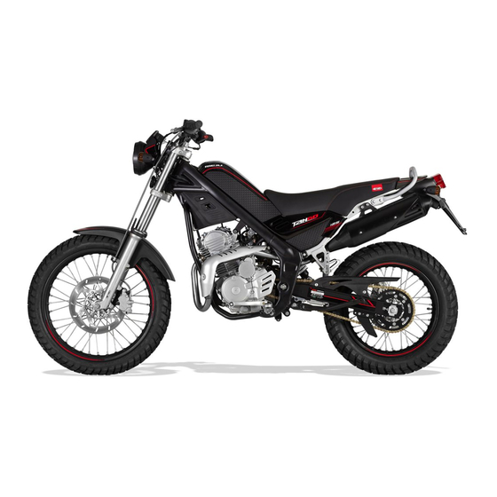
Rieju chassis Chassis UNPACKING Unpack the motorcycle following the indications appearing on the same packaging, after • that it should be thrown according to current regulations. “AESTHETIC” CONTROL Control visually that all the components of plastic material are correctly assembled and that the motorcycle does not show any scratch, mark, etc. - Page 17 Rieju chassis Chassis IDENTIFICATION OF THE MAIN PARTS (Left side) 1. Headlight 2. Rear-view mirror 3. Fuel tank 4. Battery 5. Rear direct. indicators 6. Side stand 7. Gear pedal 8. Front direct. indicators IDENTIFICATION OF THE MAIN PARTS (Right side) 9.
-
Page 18: Controls And Instruments
Rieju chassis Chassis CONTROLS AND INSTRUMENTS 1. Rear-view 7. Accelerator grip 12. Indicator switch 2. Clutch lever 8. Start switch 13. Start lever 3. Dashboard 9. Fuel tank cap 14. Horn switch 4. Main switch 10. Stop switch 5. Front brake pump 11. -
Page 19: Side Stand
Rieju chassis Chassis SIDE STAND • Make sure the lateral rest is well fixed and it moves correctly likewise it is advisable to check frequently the hold-up system, made up of drive springs. DASHBOARD “N” neutral gear warning light This warning light lits when the transmission is in the neutral gear position. -
Page 20: Pressure Control
Rieju chassis Chassis TYRES Dimensions Front: 90/100-19” 55P with tube Rear: 120/90-16” 63P with tube PRESSURE CONTROL The pressure of the tyres must be controlled and regulated with the “tyres at room tem- perature”. REAR Position 1,7 kg / cm2... -
Page 21: Transmission Oil
Rieju chassis Chassis TRANSMISSION OIL Change 1. Place the motorcycle in a flat surface. 2. Warm the engine up for some minutes. 3. Pull the engine up. Place a tray for the oil under the engine. 4. Unscrew the emptying nut (A/F -15) and the loading cap (B/F -16) to allow the oil to flow. -
Page 22: Brake Oil
Rieju chassis Chassis BRAKE OIL Control When the oil level is going to be checked, turn the handlebar to verify that the upper part of the main cylinder is levelled out. Check the oil level is above the mark of the minimum level in the tray of the rear brake. - Page 23 Rieju chassis Chassis TENSION ADJUSTMENT OF THE TRANSMISSION CHAIN The adjustment of the chain carries out loosening the rear axle of the wheel and screw in or unscrew the adjacent bolts and nuts (A/F-20), always getting the same distance on both sides of the axle.
- Page 24 Disassembly Disassembly...
- Page 25 Rieju chassis Chassis 1. SEAT Unscrew the nut (A/F -1) located inside the cavity of the rear wheel. After, lift the seat off the back and pull it backwards to remove it from the front catch (B/F -2). 2. LATERAL COVER * Remove the seat.
-
Page 26: Pillion Seat
Rieju chassis Chassis 4. PILLION SEAT * Remove the seat. Unscrew the 2 bolts (A/F -5) and remove it by the front. 5. MUFFLER Loosen the clamp (A/F -6) of the exhaust whi- ch holds the muffler. Following, unscrew the bolt (B/F-7) which holds the muffler on to the chassis. - Page 27 Rieju chassis Chassis 6. EXHAUST * Remove the left lateral cover and the left front lateral cover. To facilitate the extraction of the exhaust, remove the go-faster stripes (A/F -8). Loosen the clamp (B/F -9) of the exhaust, which holds the muffler.
- Page 28 Rieju chassis Chassis 7. BATTERY * Remove the seat. Disconnect the two cables (positive red (A/F -14) and negative (B/F -14) black). F-14 8. REAR DIRECTION INDICATORS Cut the clamp that hold the cables (A/F -15) and disconnect them from the general wiring.
-
Page 29: Air Filter
Rieju chassis Chassis 9. TAILLIGHT Disconnect the terminal (A/F -17) from the wiring. After, loosen the 2 screws (B/F -18) that hold the cover of the taillight. To extract it, pull the cable (C/F -19) to remove the light. ATTENTION: Before proceeding to the lights disassembly, pay attention to the sequence of the terminals for the later assembly (see electric diagram). -
Page 30: Componentes Eléctricos
Rieju chassis Chassis 11. REGULATOR * Remove the seat. Disconnect the regulator from the wiring (A/F -22). Following, unscrew the bolt (B/F -22) to remove it. ATTENTION: Connect the earth cable again during the assembly. F-22 12. COMPONENTES ELÉCTRICOS * Remove the seat. -
Page 31: Filter Box
Rieju chassis Chassis 14. FILTER BOX * Remove the seat, the fuel tank and the muffler. To make the task easier, unscrew the 2 bolts (A/F -24) of the rear chassis and loosen the precedent 2 (B/F -24). Loosen the nozzle (C/F -25) of the carburettor and the ventilation tube (D/F -25). -
Page 32: Shock Absorber
Rieju chassis Chassis 15. SHOCK ABSORBER * Remove the seat and the filter box. To make the task easier, unscrew the 2 bolts (A/F -27) of the rear chassis and loosen the precedent 2 (B/F -27). Unscrew the 2 bolts (A/F -28) that hold the shock absorber on to the chassis and remove it from the back. - Page 33 Rieju chassis Chassis 17. FUEL TANK * Remove the seat. ATTENTION: before proceeding to the di- sassembly, turn off the tap of the tank. Remove the clamp of the tap (A/F -30), after unscrew the 3 bolts (B/F -31) that hold the tank on to the chassis.
-
Page 34: Front Mudguards
Rieju chassis Chassis 19. SIDE STAND ATTENTION: Hold the motorcycle before carrying out this operation. Remove the tensioning spring (A/F -34). After, unscrew the bolt (B/F -34). F-34 20. FRONT MUDGUARDS Unscrew the 4 bolts (A/F -35), two in each side which hold the mudguards on to the fork. - Page 35 Rieju chassis Chassis 21. ENGINE *Remove the front lateral plates, the carburettor and the exhaust. To make the task easier, remove the rear brake lever. Disconnect the spark plug (A/F -36), the clutch cable (B/F -36) and the ventilation tube of the engine (C/F -36).
-
Page 36: Front Direction Indicators
Rieju chassis Chassis 22. FRONT DIRECTION INDICATORS Disconnect the light from the general wiring (A/F -38). After, unscrew the bolt (B/F -39). ATTENTION: Pay attention to the position of the cables for the later assembly. F-38 F-39 23. HEADLIGHT *To facilitate the task, unscrew the 3 bolts of the fuel tank and push it aside to gain access to the headlight connection. - Page 37 Rieju chassis Chassis 24. DASHBOARD * To make the task easier, put the fuel tank and the headlight aside, to gain access to the odometer connections. Disconnect the 2 terminals of the odometer (A/F -42) and the other both of the front part (B/-F43).
-
Page 38: Front Brake Pump
Rieju chassis Chassis 25. FRONT BRAKE PUMP Disconnect the micro-switch terminals of the brake light (A/F -45). Unscrew the join (B/F -45) that holds the tube on to the pump. After, unscrew the 2 bolts (C/F -46) and remove the front brake pump. - Page 39 Rieju chassis Chassis 27. HANDLEBAR * Remove the controls from each end. Unscrew the 4 bolts (A/F -48) and remove the handlebar. F-48 28. FRONT BRAKE PIN Unscrew the join through the screw (A/F - 49). Following, unscrew the 2 bolts (B/F -49) that hold the pin on to the pin support.
-
Page 40: Front Wheel
Rieju chassis Chassis 30. FRONT WHEEL ATTENTION: Loosen the fixing bolt (A/F -51) of the axle located at the fork. Unscrew the axle of the wheel and remove it. F-51 31. ODOMETER SENSOR * Remove the headlight. Disconnect the sensor (A/F -52) from the wiring and remove the screw that holds it on to the support. -
Page 41: Front Footrest
Rieju chassis Chassis 33. STEERING Unscrew the 4 bolts (A/F -55) of the handle- bar. Loosen the 2 lateral screws (B/F -55) to facili- tate its removal. Extract the top nut (C/F -55) and remove the top plate. To extract the axle, unscrew the nut (D/F - 55). -
Page 42: Rear Brake Lever
Rieju chassis Chassis 36. REAR BRAKE LEVER Unscrew the bolt (A/F -58) and remove it. F-58 37. DRIVE CHAIN GUARD Unscrew the 2 bolts (A/F -59) and remove the guard. F-59 38. TRANSMISSION CHAIN Remove the 2 fixing screws (A/F -60) from the guard and take it out. -
Page 43: Rear Brake Pump
Rieju chassis Chassis 39. REAR BRAKE PUMP Unscrew the 2 bolts (A/F -62) that hold. The brake pump on to the chassis. To remove the pump it is necessary to dis- connect the cable of the STOP switch (B/F -62) and unscrew it. - Page 44 Rieju chassis Chassis 41. SWING ARM * Remove the chain, the rear brake pin, the rear wheel and the shock absorber. Unscrew the nut (A/F -64) and remove the axle (B/F -65). F-64 F-65 42. TORQUE TORQUE TABLE Element Kg*m...
- Page 45 RIEJU, S.A. c/.Borrassà, 41 E-17600 FIGUERES, GIRONA (SPAIN) Telf. +34 / 972500850 Fax +34 / 972506950 www.riejumoto.com / e-mail rieju@riejumoto.com...