Advertisement
Quick Links
Advertisement

Related Manuals for Mercia Garden Products 04GREENLEAN0804-V2


Summary of Contents for Mercia Garden Products 04GREENLEAN0804-V2
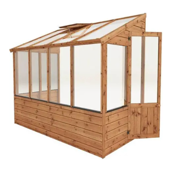
- Page 1 04GREENLEAN0804-V2 ASSEMBLY INSTRUCTIONS 8 X 4 GREENHOUSE...
- Page 2 Door Side Panel Back Side Panel Window Side Panel Window AI-04GREENDS610X1546-V2 AI-04GREENWS1193X1543-V2 AI-04GREENWS2359X1543-V2 AI-04GREENOW560X460-V2 Door Door Gable Top Plain Gable Top Roof AI-04GREENDOOR550X1720-V2 AI-04GREENLEAN0804-V2 DGT AI-04GREENLEAN0804-V2 PGT AI-04GREENLEAN0804-V2 R Roof Strip -12x56x1196mm QTY 2 S1256-1196mm Fascia -12x70x1447mm QTY 2 S1270-G-1447mm (Angled)
- Page 3 Please retain product label and instructions for future reference Strip - 12x27x610mm Strip - 12x56x1582mm QTY2 S1227-610mm F1256-1582mm Strip - 12x27x1794mm Strip - 12x27x1193mm S1227-1794mm S1227-1193mm Strip - 12x27x556mm S1227-556mm Strip - 12x27x937mm QTY 10 S1227-937mm Plastic Window Cill - 610mm PI-08-0021 Strip - 12x27x560mm S1227-560mm...
- Page 4 Please retain product label and instructions for future reference Step 1 Step 3 Arrange the base frame(s) Attatch the window strips (No. 33, 34, (No’s. 15 & 16) onto your 35, 37) using 3x30mm screws as per the base as shown in the diagram.
- Page 5 Please retain product label and instructions for future reference Step 5: Door Gable Assembly Step 4: Plain Gable Assembly Following the same method outlined Place the plain gable top (No. 7) onto the back side panel (No. 2) and secure in Step 4, place the door gable top (No.
- Page 6 Please retain product label and instructions for future reference Step 7 Step 9 Place the assembled plain gable and Following the same method outlined window side panel (No. 3) onto the in Step 7 attach the assembled door base frame(s) and x at the corners gable onto the building using 7x50mm using 3x50mm screws.
- Page 7 Please retain product label and instructions for future reference Step 11 Step 13 Attach the “L” brackets (No. 21) to either end Fix the strips (No. 9, 31, 32) onto the of the ridge bar (No. 12) using 4x30mm window frame using 3x30mm screws per screws.
- Page 8 Please retain product label and instructions for future reference Step 14 Step 15 Place the window (No. 4) into the Fix the casement stay (No. 20) to the gap in the roof (No. 8) and secure back of the opening window and onto strip (No.
- Page 9 Please retain product label and instructions for future reference Step 17 Step 18 Rest the door (No. 5) into the Fix the corner trims (No.22) in postion aperture (in the door gable) and using 4x30mm screws secure to the building with 2x butter y hinges (No.
- Page 10 Please retain product label and instructions for future reference Step 19 Step 20 Attach the fascia’s (No. 10) to Attach the door/window frame (No. 24) the top of the building, securing and two door strips (No.11) internally to the into position using 4x40mm framing around the door frame using screws per fascia.
- Page 11 P 11...
- Page 12 P 12...
Need help?
Do you have a question about the 04GREENLEAN0804-V2 and is the answer not in the manual?
Questions and answers