
Subscribe to Our Youtube Channel
Related Manuals for Longshine RCT150


Summary of Contents for Longshine RCT150
- Page 1 Flexible True Flat High Performance RCT150 USER MANUAL POS Terminal 15” All-in-One True Flat Touch Screen POS System Version: 1.0 Date: Jan 30, 2015...
- Page 2 RCT150 About this Manual Thank you for purchasing RCT150 All-in-One system. This terminal offers all the enhanced features and is easy to connect to various optional devices for optimal performance. This user manual describes how you can setup and connect your terminal.
- Page 3 RCT150 Federal Communications Commission (FCC) Declaration of Conformity This device complies with part 15 of the FCC Rules. Operation is subject to the following two conditions: This device may not cause harmful interference. This device must accept any interference received, including interference that may cause undesirable operation.
- Page 4 RCT150 BEFORE YOU PROCEED Read the safety notices and the User Manual carefully before using the product. Keep the box and packaging in case the product needs to be shipped in the future. Follow the product and warning label instructions.
- Page 5 RCT150 ! OPERATING INSTRUCTIONS Keep the User Manual for future reference. Follow the product label instructions. Lay this terminal Upside down on a stable safe surface when installing. Heavy objects placed on the product can cause damage or obstruct proper ventilation.
-
Page 6: Table Of Contents
1.1 How to use this manual ..................... 8 1.2 A Visual tour of RCT150 ..................... 9 1.2a What comes with RCT150 ................11 1.2b Dimensions of RCT150 and its optional peripheral ........12 1.3 Features of RCT150 ....................14 1.4 IO Interface ......................15 2. -
Page 7: Introduction
1.1 How to use this manual This manual contains all the information needed for setting up a RCT150. In addition, you can also consult the manual for the instructions to assemble / to service the terminal and to install the optional peripherals. -
Page 8: A Visual Tour Of Rct150
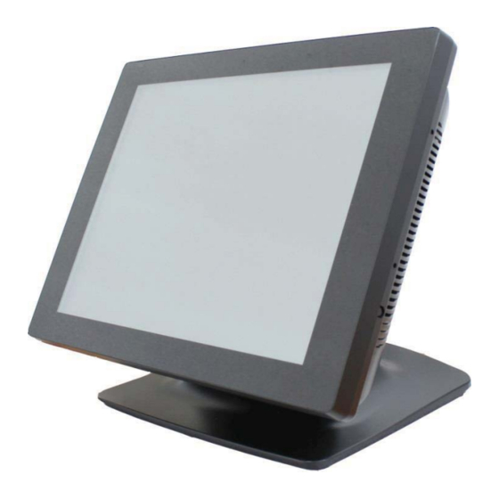
RCT150 1.2 A Visual tour of RCT150 Before you start, please take a few moments to become familiar with RCT150 Terminal. Elegant, Solid, Fashionable and Compact Design Touch screen Zero-Bezel Design Base / Stand VFD/Second display mounting hole MSR mounting... - Page 9 RCT150 “Very Easy Maintenance” Please follow the instructions to reach all inner components: Step 2: Please remove the circled five Step 1: Please position the terminal as shown below screws. on a working table with “soft protective pad”. Step 3: The back cover can now be removed.
-
Page 10: What Comes With Rct150
RCT150 1.2a What comes with RCT150 Please check if your packaging contains below listed items before setting up your RCT150. If any of the items is missing or damaged, please contact your supplier immediately. ¾ Main system with hidden power supply in the case. -
Page 11: Dimensions Of Rct150 And Its Optional Peripheral
RCT150 1.2b Dimensions of RCT150 and its optional peripheral 15” RCT150 dimensions: 15” RCT150 with MSR integrated: 15” RCT150 with 2-1 MSR+iButton module 15” RCT150 with second 7” LCD monitor integrated: integrated:... - Page 12 RCT150 15” RCT150 with second 10” LCD monitor 15” RCT150 with VFD customer display integrated: integrated:...
-
Page 13: Features Of Rct150
RCT150 features a highly durable, rigorously tested design that is reliable and dependable in rugged environments. Environment protection Environmental friendly, RoHS compliant product. High Stability RCT150 has a longer overall system MTBF to provide a higher stability during operation. Version: 1.0... -
Page 14: Io Interface
RCT150 1.4 IO Interface IO interface is located at the bottom of the display. To clearly see IO interface you must remove the cable cover. 12V DC output is connected back-end products require fire retardant case Chart of the connector panel:... -
Page 15: Hardware Setup
USB devices when the power is still on. Do not insert or remove any devices or components from RCT150 while the power is still on. Please make sure that flat touch screen will be well protected by soft pad on working table. - Page 16 RCT150 Step 4: Then remove HDD or SSD from Step 3: Dismounting HDD or SSD from the the tray. tray requires two screws to be removed. Step 5: Please insert new HDD or SSD Step 6: Please tighten left and right screws into the tray.
- Page 17 RCT150 2.2.2 Memory Step 2: Please see below where RAM module Step 1: Please remove five screws indicated below can be reached for replacement. to expose memory module. Version: 1.0...
- Page 18 RCT150 Please follow the instructions below to change memory on RCT150. Make sure that the terminal and all other peripherals which are connected to the terminal have been powered down and unplugged. 2. Disconnect all power cords and cables. 3. Locate the SO-DIMM socket on the system board.
-
Page 19: Optional Peripherals Installation
RCT150 Step 4: Connect Pin Head and push header directly into Mini PCI-E Connecter. Step 5: Please reverse step 1~2 to assemble the terminal. 2.3 Optional peripherals installation 2.3.1 Magnetic Stripe Reader Installation./ 2-1 MSR+Ibutton module Step 2: Please remove the circled five Step 1: Please position the terminal as shown below screws. - Page 20 RCT150 Step 3: Please refer to the chart below for P/N assignment of USB. function USB+ Step 4: Please tightly plug in the connector into USB pin header in correct orientation. Version: 1.0...
- Page 21 RCT150 Step 6: Using two screws to secure the MSR Step 5: Please sort the cable inside terminal housing housing to the right side of the monitor. and cut blind hole in the side. Step 8: Integration completed. Step 7: Using five screws to secure the back cover of the monitor.
-
Page 22: 2-Line Vfd Customer Display
RCT150 2.3.2 2-Line VFD customer display Step 1: Please position the terminal as shown below on a working table with “soft protective pad” Step 3: Please fix VFD to back cover. Cable should Step 2: Please check interface of VFD customer be led through the alignment hole and connect to display. - Page 23 RCT150 Step 5: Integration completed. Note: Please refer to the follow drawing and adjust the jumper on the motherboard to provide RI/+5V/ +12V power for VFD customer display. Version: 1.0...
-
Page 24: Second 7" 4-Line Lcd Display / 7" Lcd Display / 10" Lcd Display
RCT150 2.3.3 Second 7” 4-Line LCD display / 7” LCD display / 10” LCD display Step 1: Please position the terminal as shown below on a working table with “soft protective pad”. Step 3: Please remove the VESA mount cover. Cable Step 2: Please check interface of second display. -
Page 25: Service Manual
RCT150 Step 5: Please put the cover of VESA mount back to the position. Step 6: Integration completed. 3. Service manual 3.1 Touch panel Step 2: Please remove the circled five Step 1: Please position the terminal as shown below screws. -
Page 26: Lcd Panel
RCT150 Step 5: Completed. Step 6:After touch panel is replaced, please reverse the step 1-4to assemble the machine. 3.2 LCD Panel Step 2: Please remove the circled five Step 1: Please position the terminal as shown below screws. on a working table with “soft protective pad”... -
Page 27: Motherboard
RCT150 Step 5: Please remove the circled four screws. Step 6: Please remove the cable. Step 7:Completed. Step 8:After LCD panelis replaced, please reverse the step 1-7to assemble the machine. 3.3 Motherboard Step 2: Please remove the circled five Step 1: Please position the terminal as shown below screws. - Page 28 RCT150 Step 3:Please remove all connected cables Step 4:Please remove four screws of and IO interface from mother board. thermal kit as below. Step 5:Please remove the circled four screws. Step 6:Completed. Step 7:After mother board is replaced, please reverse the step 1-6to assemble the machine.
-
Page 29: Specification
RCT150 4. Specification RCT150 System Specifications Hardware Specification Intel G540 2.5Ghz/2M cache Intel Core i3-3220 3.3Ghz/3M cache Intel Core i5-3550s 3.7Ghz/6M cache Chipset Intel® H61 Chipset System Memory 2GB Standard, Maximum 8G (204-pin DDR3 SO-DIMM x 2) Audio Realtek ALC892 HD Audio 15"... - Page 30 RCT150 Windows POSReady 2009,win XP,POSReady 7,Win 7 Linux Per Request Environment Green Product RoHs,REACH EMI/Safety CE CLASS A,FCC Part 15 Subpart B,CLASS A Operating Temperature 0°C ~ 40°C (32°F ~ 104°F) Storage Temperature -10°C ~ 55°C (14°F ~131°F) Relative Humidity...
Need help?
Do you have a question about the RCT150 and is the answer not in the manual?
Questions and answers