Table of Contents

Subscribe to Our Youtube Channel
Related Manuals for Longshine POS GFT-150 Series


Summary of Contents for Longshine POS GFT-150 Series
- Page 1 Flexible / Classy / High Performance POS GFT-150 Series USER’S MANUAL All-in-One Touch Screen POS System Intel Chipset Motherboard, 15 inches LCD Monitor Available in BLACK & SILVER colors Version: 2.2 Date: January 07, 2011...
- Page 2 Preface About this Manual Thank you for purchasing POS GFT-150 Series All-in-One system. This terminal offers all the enhanced features and is easy to connect to various optional devices for optimal performance. This user manual describes how you setup and connect your terminal.
- Page 3 Preface Federal Communications Commission (FCC) Declaration of Conformity This device complies with part 15 of the FCC Rules. Operation is subject to the following two conditions: 1. This device may not cause harmful interference. 2. This device must accept any interference received, including interference that may cause undesirable operation.
- Page 4 Important Safety Information BEFORE YOU PROCEED Read the safety notices and the User’s Manual carefully before using the product. Keep the box and packaging in case the product needs to be shipped in the future. Follow the product and warning label instructions. ...
- Page 5 Important Safety Information ! OPERATING INSTRUCTIONS Keep the User’s Manual for future reference. Follow the product label instructions. Lay this terminal on a stable surface when installing. Heavy objects placed on the product can cause damage or obstruct proper ventilation. ...
-
Page 6: Table Of Contents
CONTENTS 1. Introduction............................1 Welcome............................1 1.1 How to Use This Manual ....................1 1.2 A Visual Tour of POS GFT-150 Series Terminal ............2 1.2a What Comes With POS GFT-150 Series Terminal .........4 1.2b Dimension 15” ....................7 1.2c Adjustable LCD Operation Angle..............8 1.3 Features ..........................8 ... -
Page 7: Introduction
1.1 How to Use This Manual This manual contains all the information needed for setting up a POS GFT-150 Series Terminal. In addition, you can also consult the manual for the operation system and added peripheral hardware. Provides an introduction to POS GFT-150 Series Terminal and this user’s manual. -
Page 8: A Visual Tour Of Pos Gft-150 Series Terminal
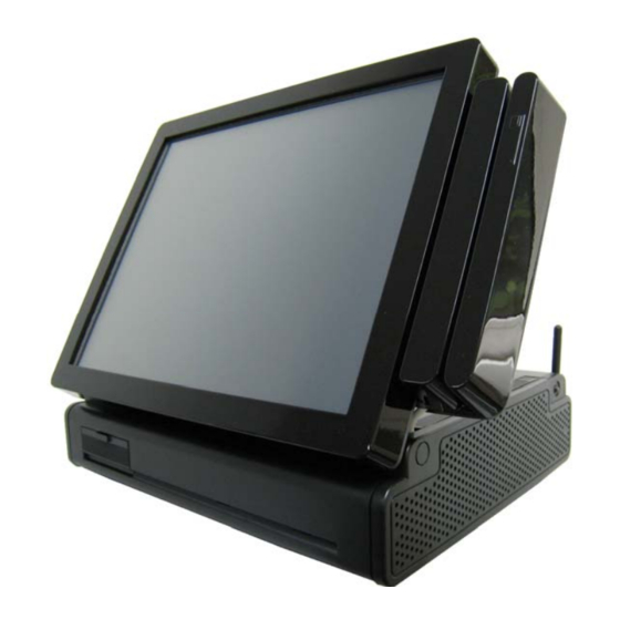
Introduction 1.2 A Visual Tour of POS GFT-150 Series Terminal Before you start, take a few moments to become familiar with POS GFT-150 Series Terminal. Elegant, Solid, Fashionable Compact Design Easy to reach I/O Connector Ports (Back Side of Machine) - Page 9 Introduction Available in 15” TFT LCD Touch 3 in 1 MSR Monitor Smartcard i-Button Reader WiFi Air Vent (on both left and right sides) Finger print-Free Front Bezel Design Auto Power Switch, Speak Hole Bright Control Cover 2011/01/07 Version: 2.2...
-
Page 10: What Comes With Pos Gft-150 Series Terminal
1.2a What Comes With POS GFT-150 Series Terminal The following items are standard with POS GFT-150 Series terminal. Before setting up your POS GFT-150 Series terminal, check that the package contains the following items. If any of the items are missing or damaged, contact your supplier immediately. - Page 11 Introduction Power adapter + AC power cord Parallel port extension cable x 1 + COM port extension cable x 2 Optional Items: 3 in 1 MSR + Smartcard + i-Button WiFi Reader Second LCD monitor 8” 10” VFD Customer Display ...
- Page 12 Introduction Peripherals Receipt Printer Cash Register Barcode Scanner 2011/01/07 Version: 2.2...
-
Page 13: Dimension 15
Introduction 1.2b Dimension 15” 15” POS GFT-150 Terminal 15” POS GFT-150 Terminal Dimensions: and MSR Dimensions: 15” POS GFT-150 Terminal 15” POS GFT-150 Terminal and VFD customer display: and second 8” or 10” LCD monitor: 2011/01/07 Version: 2.2... -
Page 14: Adjustable Lcd Operation Angle
1.2c Adjustable LCD Operation Angle “Super Firm and Perfectly Secured LCD display Angles from 0 ~ 75 degree” 1.3 Features POS GFT-150 Series terminal comes equipped with the following features: Low power consumption LV (Low Voltage) design of the device is embedded with a unique chipset and CPU renders power saving function. -
Page 15: Connector Panels
Introduction 1.4 Connector Panels The connector panel is located at the bottom of the main unit base. To clearly see the panel you must open the base cover. Chart of the connector panel: I/O Port Connector Type Description PS/2 PS/2 Mouse Use this port for an external mouse. -
Page 16: Switch Panels
Introduction 1.5 Switch Panels The switch panel is located in the front of the device. To clearly see the panel you must open the cover. HDD LED Power LED Push Button Description of Function Power On/Off switch button & Power Indicator Steady Green: The system is on. -
Page 17: Hardware Setup
Introduction 2. Hardware Setup Getting Started This section describes how to install the optional accessories on your POS GFT-150 Touch Terminal for optimal serviceability. 2.1 Pre-installation Notice Before you start installing POS GFT-150 terminal, please read the following notices carefully. 1. -
Page 18: Hardware Assembly
Hardware Setup Hardware Assembly Please make sure that the system power is turned off and the power supply is disconnected when making any hardware changes to POS GFT-150 terminal. 2.2a COM power selection Change the Jumper position Before you start using the COM port, please make sure that CN3 (for COM 4), CN5 (for COM 6), CN6 (for COM 5), CN4 (for COM 3), CN2 (for COM2), and CN1 (for COM1) on the main board are set correctly. -
Page 19: Compact Flash Installation
Hardware Setup Prepare nippers to change the position of the jumpers from Ring-IN to +5V or +12V as the picture shown below. 2.2b Compact Flash Installation…… Package Content A Compact Flash (CF) card Installing a CF Card 1. Turn off the system power. 2. -
Page 20: Magnetic Stripe Reader Installation
Specification 2.2c Magnetic Stripe Reader Installation…… An optional Magnetic Stripe Reader (MSR) can be installed on the right side of GFT-150 Terminal. An MSR A cable clip Screw x 2 Installing an MSR Turn off the system power. Using two screws to secure the MSR to the right side of the monitor. - Page 21 Specification Slide out the rear plate (A) and take off the back plate (B). Loosen the screw (C) and slide the unit outwards to reach the main board. Be aware to the LVDS cable while dragging the drawer out. Please do not drag the Note: drawer too much over, or you may tear off the LVDS cable.
- Page 22 Specification Trace the MSR cable into the unit using the cable clip on the side to secure the cable. Connect the MSR cable to the CN13 port. Replace the case, back and rear plate. Screw You may turn the system back on once the MSR is completely installed. 2011/01/07 Version: 2.2...
-
Page 23: D 2-In-1 Card Reader Installation
Specification 2.2d 2-in-1 Card Reader Installation…… An optional 2-in-1 Card Reader can be installed on the right side of GFT-150 Terminal. A 2-in-1 Card Reader A metal piece for securing 2-in-1 Card Reader A cable clip Screw x 4 Installing a 2-in-1 Card Reader Before installing a 2-in-1 Card Reader, please make sure the jumper is set correctly on the Note:... - Page 24 Specification Slide out the rear plate (A) and take off the back plate (B). Loosen the screw (C) and slide the unit outwards to reach the main board. Be aware to the LVDS cable while dragging the drawer out. Please do not drag the drawer Note: too much over, or you may tear off the LVDS cable.
- Page 25 Specification Replace the case, back and rear plate. Screw You may turn the system back on once the 2-in-1 Card Reader is completely installed. Please make sure that the power for 2-in-1 reader should be set to +5V on COM2(CN2). Note: 2011/01/07 Version: 2.2...
-
Page 26: Vfd Customer Display Installation
Specification 2.2e VFD Customer Display Installation… Package Content A VFD VFD Pole x 2 A cable clip A circular base RS-232 cable x 2 (15cm, 30cm) Screw x 2 Assemble and Disassemble the Circular pole There are two standard pole heights that may be ordered. - Page 27 Specification Installing a VFD Note: Before installing a VFD, please make sure the jumper is set correctly on the main board (Please refer to 2.2a COM power selection). The supply voltage for the customer display should be set to +12V. ...
- Page 28 Specification 4. On VFD monitor, there are two cables. Please use the longer one to connect with the COM cable. 5. Position the VFD display into the holder. 6. Connect the VFD COM cable to the COM port. 7. Turn on VFD power switch, and then turn on system power. 2011/01/07 Version: 2.2...
-
Page 29: Wifi Installation
Specification 2.2f WiFi Installation…… An optional WiFi can be installed on the right side of GFT-150 Terminal. Package Content A Mini-PCI card A detachable antenna An Antenna line A U-shape base A cable clip Screw x 2 Installing WiFi 1. - Page 30 Specification Important!! Before sliding out the drawer, please take off both the LVDS connector and the touch panel cable on the main board (marked in yellow). To remove the LVDS cable properly, please hold the connector end of the LVDS cable with fingers and carefully pull it out from the socket.
- Page 31 Specification 4. Remove the SATA HDD power cable and SATA Cable from HDD and touch cable from M/B before you pull out the drawer of M/B. 5. Screw the U-shape base to the unit, and then penetrate the antenna inside. Penetrate the Antenna line into this hole!! Buckle on the line!
- Page 32 Specification 6. Replug the LVDS connector ,the touch panel cable, HDD SATA power cable and HDD SATA Cable, and also reassemble the case, back and rear plate. Screw 7. Broken the hole on the back panel and attach the antenna on. 8.
-
Page 33: Rfid Installation
Specification 2.2g RFID Installation An optional RFID Card can be installed on the GFT-150 Terminal. Package Content An RFID card An RFID cable Screw x 2 Installing RFID 1. Turn off the system power. 2. Loosen the two screws on both sides as the picture shown below. 3. - Page 34 Specification Important!! Before sliding out the drawer, please take off both the LVDS connector and the touch panel cable on the main board (marked in yellow). To remove the LVDS cable properly, please hold the connector end of the LVDS cable with fingers and carefully pull it out from the socket.
- Page 35 Specification 4. Remove the SATA HDD power cable and SATA Cable from HDD and touch cable from M/B before you pull out the drawer of M/B. 5. Remove the RAM from the slot. Screw the RFID card to the system. After RFID card installation, replace the RAM.
- Page 36 Specification 6. On the main board, trace and connect the RFID cable to USB2/3 port. Notice Please pay attention to the USB2/3 port. The illustration shows the pin foot number. Be careful to the direction. The wrong connecting on this port may cause malfunction! USB 2 and 3 Connectors USB 3 USB 2...
- Page 37 Specification 7. Replug the LVDS connector, the touch panel cable, HDD SATA power cable and HDD SATA Cable, and also reassemble the case, back and rear plate. Screw You may turn the system back on once the RFID card is completely installed 2011/01/07 Version: 2.2...
-
Page 38: Optional Second Lcd Panel Display
Specification 2.3 Optional Second LCD Panel Display Package Content A Second Monitor A square base A power cable A 4 pin power cord Screw x 10 POS GFT-150 systems have the option of the second LCD panel display. The mechanical fitting of the second panel display is a very simple process. - Page 39 Specification 3. Slide out the rear plate (A) and take off the back plate (B). Loosen the screw (C) and slide the unit outwards to reach the main board. Loosen this screw! 4. Remove the SATA HDD power cable and SATA Cable from HDD and touch cable from M/B before you pull out the drawer of M/B.
- Page 40 Specification Important!! Before sliding out the drawer, please take off both the LVDS connector and the touch panel cable on the main board (marked in yellow). To remove the LVDS cable properly, please hold the connector end of the LVDS cable with fingers and carefully pull it out from the socket.
- Page 41 Specification 5. Use the 4 pin power cord to connect the 4 pin connector end with the 4 pin power cord of the power supply. Then, Connect the other end to the DC 12V Out connector. Last, use the 2*6 screws to secure the cord.
- Page 42 Specification 6. Replug the LVDS connector, the touch panel cable, HDD SATA power cable and HDD SATA Cable, and also reassemble the case, back and rear plate. Screw 2011/01/07 Version: 2.2...
- Page 43 Specification Installing the second monitor on the device 1. Tear off the seal on the hole. Using four screws to secure the square base holder to the unit. 2. On the Second Panel Display, plug the VGA and POWER CABLE on the relative port. 2011/01/07 Version: 2.2...
- Page 44 Specification 3. Position the Second Panel Display on the base. Trace the VGA and power cable through the base. Power cable VGA cable 4. Using four screws to fasten the Second Panel Display. 2011/01/07 Version: 2.2...
- Page 45 Specification 5. After installation, connect the VGA cable on the VGA port and power cable into DC 12V out port. 6. Last, replace the rear plate. You may turn the system back on once the Second Panel Display is completely installed. 2011/01/07 Version: 2.2...
-
Page 46: Touch Panel Replacement
Specification 2.4 Touch panel Replacement 1. Loosen the six screws to depart the front cover with touch panel from the monitor. 2. To replace Touch Panel, pleas first remove extention cable and then remove front bezel. NOTE: Please reverse the steps from step 2 to step 1 to re-install the touch panel. Pay attention to the position of each cable during re-plug (step 2). -
Page 47: Lcd Panel Replacement
Specification 2.5 LCD Panel Replacement 1. Loosen the screw on the back of the monitor and open the cover. 3. Unplug LVDS connector for LCD Panel and LCD Power cables on the rear of the monitor. LVDS connector (for LCD panel) LCD Power connector (for inverter) - Page 48 Specification 4. Please follow the instructions on chapter 2.5 Touch panel Replacement to un-install touch panel. 5. Please loosen four screws (marked in blue) to depart the panel from the bracket. Please reverse the steps from step 4 to step 1 to re-install the LCD and touch panel. Pay Note: attention to the position of each cable during re-plug (step 2).
-
Page 49: Cmos Setup
Specification CMOS Setup POS GFT-150 systems have adopted the motherboard PS960GL that uses AMI BIOS. Please refer to the PS960GL M/B User’s Manual chapter 3 for a detailed description of the BIOS CMOS setup. 2011/01/07 Version: 2.2... -
Page 50: Specification
Specification 3. Specification Technical Information System GFT-150 Model Name Motherboard ® ® Support Intel Celeron processor w/ FSB 533MHz (PS960GLE) Support Intel® Core™ 2 Duo Mobile & Penryn processor w/ FSB 533/800MHz(PS965GME) 533/800 MHz(PS965GME) System Frequency 2 DDR II SO-DIMM socket Memory Support 200-pin DDR II 533(PS960GLE) or 667(PS965GME)MHz SO-DIMM... - Page 51 Specification Others Second 8"/10" LCD Screen without Touch Monitor Optional Integrated VFD Customer Display Device MSR Card Reader 3 in 1 (MSR + Smart Card + iButton Reader) WiFi RFID Sound Speaker *There is LVDS chip onboard PS960GL M/B which is responsible for connecting the primary LCD display. However the motherboard it self has one VGA port which then can be responsible for connecting the second LCD display.
-
Page 52: Motherboard Configuration
Specification Motherboard Configuration 2011/01/07 Version: 2.2...
Need help?
Do you have a question about the POS GFT-150 Series and is the answer not in the manual?
Questions and answers