
Related Manuals for Longshine COBRA15 System Series


Summary of Contents for Longshine COBRA15 System Series
- Page 1 Fanless True Flat High Performance COBRA15 System Series USER MANUAL Windows POS systems Intel Celeron Processor J1900 technology Version: 1.0 Date: February 16, 2016...
- Page 2 COBRA15 About this Manual Thank you for purchasing COBRA15 All-in-One system. This terminal offers all the enhanced features and is easy to connect to various optional devices for optimal performance. This user manual describes how you can setup and connect your terminal. Copyright The information in this guide is subject to change without prior notice.©...
- Page 3 COBRA15 Federal Communications Commission (FCC) Declaration of Conformity This device complies with part 15 of the FCC Rules. Operation is subject to the following two conditions: 1. This device may not cause harmful interference. 2. This device must accept any interference received, including interference that may cause undesirable operation.
- Page 4 COBRA15 compliance could void the user’s authority to operate this equipment. RoHS 2016/02/15 Version: 1.0...
- Page 5 COBRA15 BEFORE YOU PROCEED Read the safety notices and the User Manual carefully before using the product. Keep the box and packaging in case the product needs to be shipped in the future. Follow the product and warning label instructions. ...
- Page 6 COBRA15 ! OPERATING INSTRUCTIONS Keep the User Manual for future reference. Follow the product label instructions. Lay this terminal Upside down on a stable safe surface when installing. Heavy objects placed on the product can cause damage or obstruct proper ventilation. ...
-
Page 7: Table Of Contents
COBRA15 CONTENTS 1. Introduction ............................. 8 1.1 How to use this manual ....................8 1.2 A Visual tour of COBRA15 ....................9 1.2a What comes with COBRA15 ................13 1.2b Dimensions of COBRA15 and its optional peripherals ........15 1.3 Features of COBRA15 ....................17 1.4 IO Interface ........................ -
Page 8: Introduction
COBRA15 1. Introduction Thank you for purchasing POS COBRA15 Series Terminal. Read this chapter to know about your POS COBRA15 Series Terminal package contents, outlook and dimensions. 1.1 How to use this manual This manual contains all the information needed for setting up a COBRA15. In addition, you can also consult the manual for the instructions to assemble / to service the terminal and to install the optional peripherals. -
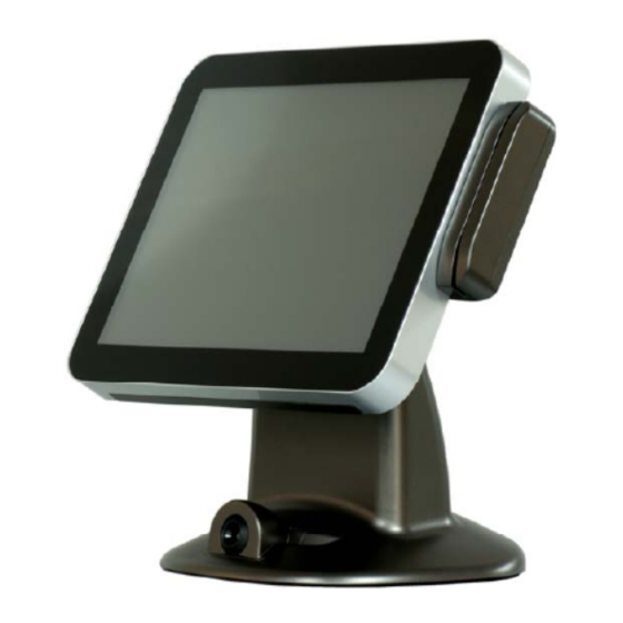
Page 9: A Visual Tour Of Cobra15
COBRA15 1.2 A Visual tour of COBRA15 Before you start, please take a few moments to become familiar with COBRA15 Terminal. Elegant, Solid, Fashionable and Compact Design Item No Description Touch screen Removable Hard drive Extraction slot POWER LED Base / Stand Optional devices Version: 1.0... - Page 10 COBRA15 Item No Description Function cover Optional for VFD ,7” Secondary Display cover MSR cover Speaker holes (speaker Optional) HDD Cover Switch cover Cable cover Version: 1.0...
- Page 11 COBRA15 “Very Easy Maintenance” Please follow the instructions to reach all inner components: Step 2: Please remove cable cover by Step 1: Please position the terminal as shown below sliding it downwards. on a working table with “soft protective pad”. Push Push Step 4: Please disconnect and remove all the...
- Page 12 COBRA15 Step 5: Please unplug and remove the hard Step 6: The back cover can now be removed. disk. Only authorized system engineers are advised to disassemble the device. Please be aware that unauthorized modifications will void your warranty. You are advised to contact your authorized supplier for technical support. Version: 1.0...
-
Page 13: What Comes With Cobra15
COBRA15 1.2a What comes with COBRA15 Please check if your packaging contains below listed items before setting up your COBRA15. If any of the items is missing or damaged, please contact your supplier immediately. Main system with hidden power adapter in the stand. ... - Page 14 COBRA15 COBRA15 with 2D Image scanner COBRA15 with VFD customer display COBRA15 with i-Button COBRA15 with ADDIMAT reader reader COBRA15 with second 7” LCD display Version: 1.0...
-
Page 15: Dimensions Of Cobra15 And Its Optional Peripherals
COBRA15 1.2b Dimensions of COBRA15 and its optional peripherals 15” COBRA15 dimensions: 15” COBRA15 with MSR+RFID integrated: 15” COBRA15 with VFD customer display 15” COBRA15 with 7”second display integrated: integrated: Version: 1.0... - Page 16 COBRA15 Version: 1.0...
-
Page 17: Features Of Cobra15
COBRA15 1.3 Features of COBRA15 Low power consumption LV (Low Voltage) design of the device is embedded with a unique chipset and CPU renders power saving function. Saving cost of ownership Modular design provides the owner with the following benefits: (a) cost effectiveness, (b) customization flexibility, and... -
Page 18: Io Interface
COBRA15 1.4 IO Interface IO interface is located at the bottom of the display. To clearly see IO interface you must remove the cable cover. Chart of the connector panel: Item No Description Power DC-IN 12V 2 USB 2.0 LAN 10/100/1000Mbps Ethernet VGA Connector 2 USB 2.0 Line out... -
Page 19: Hardware Assembly
COBRA15 2. Hardware assembly Please make sure that the system power is turned off and the power supply is disconnected when making any hardware changes to COBRA15. 2.1.1 HDD + SSD Step 1: Please remove the HDD Step 2: Please pull out and retrieve screw. - Page 20 COBRA15 Step 8: Please tighten the circled Step 7: Please push in HDD or SSD into the terminal screw to complete the installation. where indicated below. Version: 1.0...
-
Page 21: Memory
COBRA15 2.1.2 Memory Please follow the instructions below to change memory on COBRA15. 1. Make sure that the terminal and all other peripherals which are connected to the terminal have been powered down and unplugged. 2. Disconnect all power cords and cables. 3. - Page 22 COBRA15 5. Push down the module until the clips at each end of the socket lock into position. You will hear a distinctive click, indicating the module is correctly locked into position. Clip Clip Version: 1.0...
-
Page 23: Mini-Pci-E M-Sata Ssd
COBRA15 2.1.3 Mini-PCI-E m-SATA SSD Step 1: Please position the terminal as shown below Step 2: Please remove cable cover by on a working table with “soft protective pad”. sliding it downwards. Push Push Step 4: Please disconnect and remove all the Step 3: Please remove the circled six connected cables from IO interface and unscrew screws. - Page 24 COBRA15 Step 5: Please unplug and remove the Step 6: The back cover can now be removed. hard disk. Step 7: Mini PCI-E Connecter can then be found where circled. Connect Pin Head and push header directly into Mini PCI-E Connecter. Version: 1.0...
-
Page 25: Optional Peripherals Installation
COBRA15 2.2 Optional peripherals installation 2.4.1 MSR Step 1: Please position the terminal as shown below on a working table with “soft protective pad”. Step 2: Please remove MSR cover to find USB connecter. Step 3: Please refer to the chart below for P/N assignment of USB. Terminal does not support P/S2 interface. - Page 26 COBRA15 Step 4: Please tightly plug in the connector into USB pin header in correct orientation. Step 5: Please sort the cable inside MSR housing and lock the two screws indicated below. Step 6: Integration completed. Version: 1.0...
-
Page 27: Line Vfd Customer Display
COBRA15 2.4.2 2-Line VFD customer display Step 1: Please remove four screws indicated below. Step 2: Please remove four screws indicated below to release the display cover. Step 4: Please fix VFD to function cover as Step 3: Please check interface of VFD customer shown below. - Page 28 COBRA15 Step 5: Please screw four screws indicated below to fix VFD customer display on to function cover. Step 6: Please follow the USB2.0 connector Pin define before insert the VFD cable. Step 7: Please screw four screws indicated below to install VFD customer display to COBRA15. Version: 1.0...
- Page 29 COBRA15 Step 8: Integration completed. Only authorized system engineers are advised to disassemble the device. Please be aware that unauthorized modifications will void your warranty. You are advised to contact your authorized supplier for technical support. Version: 1.0...
-
Page 30: Second 7" Lcd Display
COBRA15 2.2.3 Second 7” LCD display Step 1: Please remove screws indicated below. Step 2: Please remove four screws indicated below to release the display cover. Step 3: Please fix second display to function cover and screw four screws as shown below. Cable should be led through the alignment hole. - Page 31 COBRA15 Step 4: Please follow the USB2.0 connector Pin define before insert the VGA cable. Step 5: Please screw four screws indicated below to install LCD display to COBRA15. Version: 1.0...
- Page 32 COBRA15 Step 6: Integration completed. Version: 1.0...
-
Page 33: Touch Panel Calibration
COBRA15 3 Software Setup This chapter introduces how to install driver & calibrate touch panel for POS COBRA15 Touch Panel calibration COBRA15 can support Win 7 and Win8.1. Before using COBRA15, please install the OS system as factory recommend. Please follow the below instructions to calibrate the touch panel when successfully install OS system. - Page 34 COBRA15 STEP 2 Please open “eGalax Touch” program to select “Tool” page and click “4 points calibration” items for touch panel calibration. Version: 1.0...
- Page 35 COBRA15 STEP 3 Please click 4 points of screen for calibration. Version: 1.0...
- Page 36 COBRA15 Version: 1.0...
- Page 37 COBRA15 STEP 4 After 4 points calibration complete, please click “ok” as below picture to continue using the terminal. Version: 1.0...
- Page 38 COBRA15 Important Notice: Please calibrate the touch panel before using the ternimal. Version: 1.0...
-
Page 39: Specification
COBRA15 4. Specification Hardware Specification Intel® Celeron® Processor J1900 (Clockspeed: 2.0 GHz, Turbo Speed: 2.4 GHz, Cores: 4) System Memory 2GB Standard, Maximum 8G (DDR3L SO-DIMM scoket x 2) Graphics Intel® Gen7 Intel® Graphics DX 11, OGL3.2 Audio Realtek ALC662 HD Audio 15"... - Page 40 COBRA15 Relative Humidity 10% ~ 90% (Non-Condensing) Dimension Dimension 365.3(W) x 234(D) x 394.7(H) mm Weight 7.9Kg Other Indicator Powe LED Button Power on/off , Reset,UP/Down Buzzer Product specifications are subject to change without prior notice Version: 1.0...
Need help?
Do you have a question about the COBRA15 System Series and is the answer not in the manual?
Questions and answers