
Subscribe to Our Youtube Channel
Related Manuals for Longshine GFT-150 Series


Summary of Contents for Longshine GFT-150 Series
- Page 1 Flexible / Classy / High Performance POS GFT-150 Series USER’S MANUAL Windows POS System Intel Chipset Motherboard, 15 inches LCD Monitor Available in BLACK & SILVER colors Version: 1.1 Date: February 15, 2016...
- Page 2 Preface About this Manual Thank you for purchasing POS GFT-150 Series All-in-One system. This terminal offers all the enhanced features and is easy to connect to various optional devices for optimal performance. This user manual describes how you setup and connect your terminal.
- Page 3 Preface Federal Communications Commission (FCC) Declaration of Conformity This device complies with part 15 of the FCC Rules. Operation is subject to the following two conditions: 1. This device may not cause harmful interference. 2. This device must accept any interference received, including interference that may cause undesirable operation.
- Page 4 Important Safety Information BEFORE YOU PROCEED Read the safety notices and the User’s Manual carefully before using the product. Keep the box and packaging in case the product needs to be shipped in the future. Follow the product and warning label instructions. ...
- Page 5 Important Safety Information OPERATING INSTRUCTIONS Keep the User’s Manual for future reference. Follow the product label instructions. Lay this terminal on a stable surface when installing. Heavy objects placed on the product can cause damage or obstruct proper ventilation. ...
-
Page 6: Table Of Contents
Index CONTENTS INTRODUCTION........................7 ........................7 ACKAGE ONTENTS ............................9 EATURE .............................10 UTLOOK ....................12 IMENSION AND PERATION NGLE .........................14 ONNECTOR ANEL ........................14 ONTROL UTTONS HARDWARE SETUP ........................ 16 .......................16 INSTALLATION OTICE ........................16 ARDWARE SSEMBLY 2.2-1 Motherboard Introduction ........................16 2.2-2 MSR Installation ..........................20 2.2-3 2-in-1 Reader Installation ........................22 2.2-4... -
Page 7: Introduction
Parallel port extension cable x 1 + COM port extension cable x 2 Besides above standard items with POS GFT-150 Series terminal, we also provide MSR, VFD customer display, 2-in-1 Reader and peripheral accessories as an optional. Please refer to below... - Page 8 Introduction VFD Customer Display Peripherals Receipt Printer Cash Register Barcode Scanner 2016/02/15 Version: 1.1...
-
Page 9: Feature
Introduction 1.2 Feature POS GFT-150 Series terminal comes equipped with the following features: Low power consumption Low Voltage design of the device is embedded with a unique chipset and CPU renders power saving function. Saving cost of ownership... -
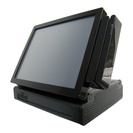
Page 10: Outlook
Introduction 1.3 Outlook GFT-150 POS terminal is easy-to-use and designed to enhance user business flexibility by offering a superior customer experience. Please follow the below instructions for more info of GFT-150 Series Terminal outlook and dimension. Elegant, Solid, Fashionable Compact Design Easy to reach I/O Connector Ports (Back Side of Machine) MSR / 2-in-1 Reader Mounting... - Page 11 Introduction Available in 15” TFT LCD Touch Monitor 2-in-1 Reader Air Vent (on both left and right sides) Finger print-Free Front Bezel Design Auto Power Switch, Speak Hole Bright Control Cover 2016/02/15 Version: 1.1...
-
Page 12: Dimension And Operation Angle
Introduction 1.4 Dimension and Operation Angle 15” POS GFT-150 Terminal 15” POS GFT-150 Terminal Dimensions: and MSR Dimensions: 15” POS GFT-150 Terminal 15” POS GFT-150 Terminal and VFD customer display: and second 8” or 10” LCD monitor: 2016/02/15 Version: 1.1... - Page 13 Introduction Adjustable LCD Operation Angle “Super Firm and Perfectly Secured LCD display Angles from 0 ~ 75 degree.” 2016/02/15 Version: 1.1...
-
Page 14: Connector Panel
Hardware Setup 1.5 Connector Panel The connector panel is located at the back of the machine. Please refer to below for more info of connector I/O ports. Chart of the connector panel: I/O Port Connector Type Description COM 1, COM2 / COM3 / COM4 Serial Ports with 5V/12V COM Port RJ-11 Connector power selectable... - Page 15 Hardware Setup control buttons. HDD LED Power LED Push Button Description of Function Power On/Off switch button & Power Indicator Steady Green: The system is on. Power LED Indicator Off: The system is off. Blinking Red: The device is read/write data on hard disk. HDD LED Indicator Off: No action on the device.
-
Page 16: Hardware Setup
Soft remind that the system power must be off and disconnect to power supply during assembling hardware. 2.2-1 Motherboard Introduction POS GFT-150 series are embedded main board which support to adjust power electricity and setup optional accessories to the device. Please follow the below steps for motherboard setting. STEP 1 Please Loosen the two screws on both sides as the picture shown below. - Page 17 Hardware Setup STEP 2 Slide out the rear plate STEP 3 Loosen below screw at the button of I/O connector panel and slide the case outwards. STEP 4 Remove the monitor cover. 2016/02/15 Version: 1.1...
- Page 18 Hardware Setup STEP 5 When successfully unscrew POS GFT-150 mental piece and reach main board, kindly refer to below table for main board introduction. Item Function DC_JACK USB 2.0 Port LAN RJ_45 Port VGA Port (VGA1) USB 2.0 Port HDMI Port (HDMI1) Line Out (Green) Microphone (Pink) PWR_COM3 Jumper...
- Page 19 Hardware Setup PWR_COM4 Jumper PWR_COM6 Jumper Internal COM Port Headers COM 1, 2, 3, 4, 6 (RS232) Printer Port Header USB 2.0 Connector mSATA Select 1-2: SATA2_2 + mini PCIe 2-3: mSATA, SATA2_2 no function USB 2.0 Connector for MSR / 2-in-1 Reader Important Notice: The default power electricity for GFT-150 COM port is 0, please follow item 9, 10, 11 intructions to change the power electricity.
-
Page 20: Msr Installation
Hardware Setup 2.2-2 MSR Installation An optional Magnetic Stripe Reader (MSR) can be installed on the right side of GFT-150 Terminal. This chapter will indicate how to install MSR on your device. Before installing, kindly check the package content first. The MSR package content includes: An MSR with cable clip Screw * 2... - Page 21 Hardware Setup STEP 4 When plug MSR cable to USB pin header successfully, please secure the cable with cable clip. STEP 5 Assemble the terminal when MSR integration completed. Important Notice: Be aware to the LVDS cable while dragging the drawer out. Please do not drag the drawer too much over, or you may tear off the LVDS cable.
-
Page 22: 2-In-1 Reader Installation
Hardware Setup 2.2-3 2-in-1 Reader Installation An optional 2-in-1 Reader can be installed on the right side of GFT-150 Terminal. The 2-in-1 reader package content includes: An 2-in-1 reader with cable clip A metal piece for securing 2-in-1 Card Reader Screw * 4 Install 2-in-1 card reader for your GFT-150: STEP 1... - Page 23 Hardware Setup STEP 4 When plug cable to USB pin header successfully, please secure the cable with cable clip. STEP 5 Assemble the terminal when MSR integration completed. Important Notice: Be aware to the LVDS cable while dragging the drawer out. Please do not drag the drawer too much over, or you may tear off the LVDS cable.
-
Page 24: Vfd Customer Display Installation
Hardware Setup 2.2-4 VFD Customer Display Installation Package Content A VFD VFD Pole x 2 A cable clip A circular base RS-232 cable x 2 (15cm, 30cm) Screw x 2 Assemble and Disassemble the Circular pole There are two standard pole heights that may be ordered. - Page 25 Hardware Setup Installing a VFD STEP 1 Turn off the system power and screw the VFD Holder to the base. STEP 2 Trace the COM cable through the VFD holder If you are using poles, please also trace the COM cable through the pole.
- Page 26 Hardware Setup STEP 4 Position the VFD display into the holder and Connect the VFD cable to the COM 2, 3 or 4. STEP 5 Turn on VFD power switch and then turn on system power. Important Notice: The default power electricity for GFT-150 COM port is 0. Please change the power electricity to 12V before installing VFD customer display.
-
Page 27: Hdd/ Sdd Kit Installation
Hardware Setup 2.2-5 HDD/ SDD Kit Installation GFT-150 embedded 2.5" SATA II HDD/SSD kit as the factory setting. User can exchange storage if needed. Please follow the below instructions for exchanging storage. STEP 1 Please turn off the system power. STEP 2 Please position the terminal as shown below on the working table and find the 2.5”... - Page 28 Hardware Setup Important Notice: The terminal may be damaged if user aslant push in HDD / SSD kit. Please parallel push HDD or SSD kit into the device. 2016/02/15 Version: 1.1...
-
Page 29: Software Setup
Software Setup 3. Software Setup This chapter introduces how to install driver & calibrate touch panel for POS GFT-150 3.1 Touch Panel calibration GFT-150 can support Win 7 and Win8.1. Before using RDT-150F, please install the OS system as factory recommend. Please follow the below instructions to calibrate the touch panel when successfully install OS system. - Page 30 Software Setup STEP 2 Please open “eGalax Touch” program to select “Tool” page and click “4 points calibration” items for touch panel calibration. 2016/02/15 Version: 1.1...
- Page 31 Software Setup STEP 3 Please click 4 points of screen for calibration. 2016/02/15 Version: 1.1...
- Page 32 Software Setup 2016/02/15 Version: 1.1...
- Page 33 Software Setup STEP 4 After 4 points calibration complete, please click “ok” as below picture to continue using the terminal. Important Notice: Please calibrate the touch panel before using the ternimal. 2016/02/15 Version: 1.1...
-
Page 34: Specifications
Specifications 4. Specifications Hardware Specification Intel® Celeron® Processor J1900 (Clockspeed: 2.0 GHz, Turbo Speed: 2.4 GHz, Cores: 4) System Memory 2GB Standard, Maximum 8G (DDR3L SO-DIMM scoket x 2) Graphics Intel® Gen7 Intel® Graphics DX 11, OGL3.2 Audio Realtek ALC662 HD Audio 15"... - Page 35 Specifications EMI/Safety CE, FCC Class A Operating 0°C ~ 40°C (32°F ~ 104°F) Temperature Storage Temperature -10°C ~ 55°C (14°F ~131°F) Relative Humidity 10% ~ 90% (Non-Condensing) Dimension Dimension 354(W) x 281(D) x 336(H) mm Weight 6.7Kg Other Indicator Powe LED + HDD LED Button Power on/off , Reset,UP/Down Buzzer...
Need help?
Do you have a question about the GFT-150 Series and is the answer not in the manual?
Questions and answers