Table of Contents
Advertisement
Quick Links
UM1775
User manual
Discovery kit with STM32L053C8 MCU
Introduction
The STM32L053 Discovery kit (32L0358DISCOVERY) helps the user to discover the full
feature range of the STM32L0 Series and develop applications. It is based on the
STM32L053C8T6 microcontroller and includes an embedded ST-LINK/V2-1
debugger/programmer, linear touch sensor, touchkeys, I
current measurement, 2.13" E-
DD
paper display, NFC connector for the PLUG-CR95HF-B board, LEDs, push-buttons and a
USB Mini-B connector.
The STM32L053 Discovery kit comes with a comprehensive STM32 software HAL library
with various packaged software examples available in the STM32CubeL0 MCU Package,
®
as well as direct access to Arm
Mbed™ on-line resources at https://os.mbed.com/.
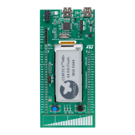
Figure 1. STM32L053 Discovery board
Picture is not contractual.
September 2021
UM1775 Rev 4
1/39
www.st.com
Advertisement
Table of Contents

Related Manuals for ST STM32L053


Summary of Contents for ST STM32L053
-
Page 1: Figure 1. Stm32L053 Discovery Board
User manual Discovery kit with STM32L053C8 MCU Introduction The STM32L053 Discovery kit (32L0358DISCOVERY) helps the user to discover the full feature range of the STM32L0 Series and develop applications. It is based on the STM32L053C8T6 microcontroller and includes an embedded ST-LINK/V2-1 debugger/programmer, linear touch sensor, touchkeys, I current measurement, 2.13”... -
Page 2: Table Of Contents
Embedded ST-LINK/V2-1 ........13... - Page 3 UM1775 Contents 6.11 USART configuration ........23 6.12 OSC clock supply .
- Page 4 List of tables UM1775 List of tables Table 1. Ordering information ............7 Table 2.
- Page 5 STM32L053 Discovery board connections ........
-
Page 6: Features
Features UM1775 Features The STM32L053 Discovery kit offers the following features: • STM32L053C8T6 microcontroller with 64 Kbytes of Flash memory and 8 Kbytes of RAM, in an LQFP48 package • 2.13" E-paper display, 122×250 pixels • USB 2.0 FS •... -
Page 7: Ordering Information
UM1775 Ordering information Ordering information To order the 32L0358DISCOVERY Discovery kit, refer to Table 1. Additional information is available from the datasheet and reference manual of the target microcontroller. Table 1. Ordering information Order code Board reference Target STM32 STM32L0538-DISCO MB1143 STM32L053C8T6 Codification... -
Page 8: Development Environment
Development environment UM1775 Development environment System requirements ® ® (a) ® (b) • Multi.OS support: Windows 10, Linux 64-bit, or macOS ® • USB Type-A or USB Type-C to Mini-B cable Development toolchains ® (c) • IAR Systems - IAR Embedded Workbench ®... -
Page 9: Quick Start
UM1775 Quick start Quick start The STM32L053 Discovery kit is a low-cost and easy-to-use development kit to quickly evaluate and start a development with the STM32L053C8T6 ultra-low-power microcontroller in the STM32L0 Series. Before installing and using the product, accept the Evaluation Product License Agreement from the www.st.com/stm32l0-discovery webpage. -
Page 10: Hardware Layout
Hardware layout UM1775 Hardware layout The STM32L053 Discovery board is designed around the STM32L053C8T6 microcontroller in a 48-pin LQFP package. Figure 2 illustrates the connections between the STM32L053C8T6 and its peripherals (ST- LINK/V2-1, linear touch sensor, touchkeys, I current measurement, 2.13” E-paper display, NFC connector for PLUG-CR95HF-B board, LEDs, push-buttons and an USB Mini- B connector). -
Page 11: Figure 3. Top Layout
UM1775 Hardware layout Figure 3. Top layout ST-LINK/V2-1 (LD2) USB ST-LINK USB USER (LD1) NFC connector (CN1) Reserved (JP1) Reserved (JP2) ST-LINK/DISCOVERY selector (CN4) RX,TX (JP3) VCP RX, TX 5 V power (SB2, SB3) supply input 3 V power supply output... -
Page 12: Figure 4. Bottom Layout
Hardware layout UM1775 Figure 4. Bottom layout Reserved (SB4, 5, 6, 11) Default (SB7,8,9,12) STM_RST (SB10) NRST (SB13) RX, TX (SB14,15) X2 crystal (SB18,19) Crystal USB_USER (X2) (SB16, 17) (SB20) STM32L053C8T6 (U8) OSC_IN (SB21) B2 – RESET B1 – USER (SB29) (SB22) Touch sensor... -
Page 13: Embedded St-Link/V2-1
Windows 10, is available from www.st.com. In cases where the STM32L053 Discovery board is connected to the PC before the driver is installed, some STM32L053 Discovery board interfaces might be declared as “Unknown” in the PC device manager. In this case, the user must install the dedicated driver files and... -
Page 14: St-Link/V2-1 Firmware Upgrade
ST-LINK/V2-1 firmware upgrade ST-LINK/V2-1 embeds a firmware upgrade mechanism for in-situ upgrade through the USB port. As the firmware may evolve during the life time of the ST-LINK/V2-1 product (for example new functionalities, bug fixes, support for new microcontroller families), visiting the www.st.com... -
Page 15: Using St-Link/V2-1 To Program/Debug The Stm32L053C8T6 On Board
To program the STM32L053C8T6 on board, simply plug in the two jumpers on CN4, as shown in Figure 6 in pink, but do not use the CN5 connector as that could disturb the communication with the STM32L053C8T6 of the STM32L053 Discovery board. Figure 6. STM32L053 Discovery board connections UM1775 Rev 4 15/39... -
Page 16: Using St-Link/V2-1 To Program/Debug An External
6.1.5 Using ST-LINK/V2-1 to program/debug an external STM32 application It is very easy to use ST-LINK/V2-1 to program an STM32 microcontroller on an external application. Simply remove the two jumpers from CN4 as shown in Figure 7 and connect the... -
Page 17: Power Supply And Power Selection
The power supply is provided either by the host PC through the USB cable, or by an external 5 V power supply. The STM32L053 Discovery board requires 300 mA from the host PC: about 90 mA are needed by a simple E-paper demo application, 100 mA for an extension board, and 100 mA as a safety margin. -
Page 18: Power Supply Input From The Usb Connector
5 V can also be used as input power supply, for instance when the USB connector is not connected to the PC (pin 5V_I of header P3). In this case, the STM32L053 Discovery board must be powered by a power supply unit or by an auxiliary equipment complying with standard EN-60950-1: 2006+A11/2009. It must be Safety Extra Low Voltage (SELV) with limited power capability. -
Page 19: External Power Supply Inputs: 5V_In Or Usb User Cn3
The external power source 5V_IN or USB USER CN3 is automatically detected. In this case the current consumption of the STM32L053 Discovery board and its extension board may exceed the allowed current on the USB. In this condition it is still possible to use the USB for communication, for programming or debugging only, but it is mandatory to power supply the board first using 5V_IN or USB USER CN3 then connecting the USB cable to the PC. -
Page 20: Nfc Connector For Plug-Cr95Hf-B Board
A NFC (Near Field Communication) transceiver board can be connected to the STM32L053 Discovery board, for example the PLUG-CR95HF-B board. The NFC board is plugged in connector CN1 of STM32L053 Discovery board as following: Figure 8. NFC board plugged on the STM32L053 Discovery board... -
Page 21: Electronic Paper Display (Epd)
Main power supply/power supply for RF drivers Ground Electronic paper display (EPD) The STM32L053 Discovery board includes an E-paper display with high contrast, high reflectance and ultra-wide viewing angle. This display is a TFT active matrix electrophoretic display. The 2.13" active area contains 122×250 pixels and it is capable to display images at 1-bit white, black full display... -
Page 22: Boot0 Configuration
6 mA while connecting pin P2.6 (BOOT0) and P2.5 (VDD) with a jumper or a wire. Linear touch sensor / touchkeys To demonstrate touch sensing capabilities, the STM32L053 Discovery board includes a linear touch sensor, which can be used either as a three-position linear touch sensor or as four touchkeys. -
Page 23: Usb Device Support
The STM32L053C8T6 MCU is also used to drive the second USB Mini-B connector (USB USER), which allows the use of the board as a USB Device. The STM32L053 Discovery board can then act as a USB joystick, mouse, or other similar device. If both USBs are... -
Page 24: Osc 32 Khz Clock Supply
Hardware layout UM1775 6.13 OSC 32 KHz clock supply If PC14 and PC15 are only used as GPIOs instead of as a clock, then SB18 and SB19 are ON and R70 and R71 are removed. HSE oscillator onboard from X2 crystal (not provided) For typical frequencies and its capacitors and resistors, please refer to the STM32L053C8T6 Datasheet. -
Page 25: Solder Bridges
PA2, PA3, PA6, PA7, PB0, PB1 are available as GPIO on P2, P3 headers. ST-LINK/V2-1 module is powered SB1 (ST-LINK/V2-1 PWR) ST-LINK/V2-1 module is not powered Clock signal from header P3.7 is connected to OSC_IN of STM32L053C8T6 or PH0 is available as GPIO. SB20 must be OFF SB21 (OSC_IN) No connection between header P3.7 and PH0 of STM32L053C8T6... -
Page 26: Extension Connectors
6.15 Extension connectors The male headers P2 and P3 can connect the STM32L053 Discovery board to a standard prototyping/wrapping board. STM32L053C8T6 GPIOs are available on these connectors. P2 and P3 can also be probed by an oscilloscope, logical analyzer or voltmeter. - Page 27 UM1775 Hardware layout Table 8. Extension connectors (continued) MCU pin Board function PA10 PA11 PA12 PA13 PA14 PA15 UM1775 Rev 4 27/39...
- Page 28 Hardware layout UM1775 Table 8. Extension connectors (continued) MCU pin Board function 28/39 UM1775 Rev 4...
- Page 29 UM1775 Hardware layout Table 8. Extension connectors (continued) MCU pin Board function PB10 PB11 PB12 PB13 PB14 PB15 PC13 UM1775 Rev 4 29/39...
- Page 30 Hardware layout UM1775 Table 8. Extension connectors (continued) MCU pin Board function PC14 PC15 VDD_USB VDDA VLCD 30/39 UM1775 Rev 4...
- Page 31 UM1775 Hardware layout Table 8. Extension connectors (continued) MCU pin Board function VSSA 1. Signals available depending on SBx value. Refer to Table 7: Solder bridges. 2. Connected through a resistor UM1775 Rev 4 31/39...
-
Page 32: Mechanical Drawing
Mechanical drawing UM1775 Mechanical drawing Figure 12. STM32L053 Discovery board mechanical drawing 32/39 UM1775 Rev 4... -
Page 33: 32L0358Discovery Discovery Kit Information
Any consequences deriving from such usage will not be at ST charge. In no event, ST will be liable for any customer usage of these engineering sample tools as reference designs or in production. -
Page 34: 32L0358Discovery Product History
32L0358DISCOVERY Discovery kit information UM1775 32L0358DISCOVERY product history 8.2.1 Product identification 32L0538DISCO/ This product identification is based on the mother board MB1143-Default-B01. It embeds the STM32L053C8T6 microcontroller with silicon revision code "Z". The limitations of this silicon revision are detailed in the errata sheet STM32L053x6/8 device errata (ES0253). -
Page 35: Appendix A Federal Communications Commission (Fcc)
UM1775 Federal Communications Commission (FCC) and ISED Canada Compliance Statements Appendix A Federal Communications Commission (FCC) and ISED Canada Compliance Statements FCC Compliance Statement A.1.1 Part 15.19 This device complies with Part 15 of the FCC Rules. Operation is subject to the following two conditions: (1) this device may not cause harmful interference, and (2) this device must accept any interference received, including interference that may cause undesired operation. -
Page 36: Ised Compliance Statement
Federal Communications Commission (FCC) and ISED Canada Compliance Statements UM1775 ISED Compliance Statement Compliance Statement ISED Canada ICES-003 Compliance Label: CAN ICES-3 (B) / NMB-3 (B). Déclaration de conformité Étiquette de conformité à la NMB-003 d'ISDE Canada : CAN ICES-3 (B) / NMB-3 (B). 36/39 UM1775 Rev 4... -
Page 37: Appendix Bce Conformity
UM1775 CE conformity Appendix B CE conformity EN 55032 / CISPR32 (2012) Class B product Warning: This device is compliant with Class B of EN55032 / CISPR32. In a residential environment, this equipment may cause radio interference. Avertissement : cet équipement est conforme à la Classe B de la EN55032 / CISPR 32. Dans un environnement résidentiel, cet équipement peut créer des interférences radio. -
Page 38: Revision History
Section 6.1: Embedded ST-LINK/V2-1, Section 6.6: Electronic paper display (EPD) Section 6.9: Linear touch sensor / touchkeys. 10-Sep-2021 Updated Figure 2: STM32L053 Discovery board hardware block diagram Figure 3: Top layout. Revised the beginning of the document: – Updated Introduction, Section 1:... - Page 39 ST products and/or to this document at any time without notice. Purchasers should obtain the latest relevant information on ST products before placing orders. ST products are sold pursuant to ST’s terms and conditions of sale in place at the time of order acknowledgement.
Need help?
Do you have a question about the STM32L053 and is the answer not in the manual?
Questions and answers