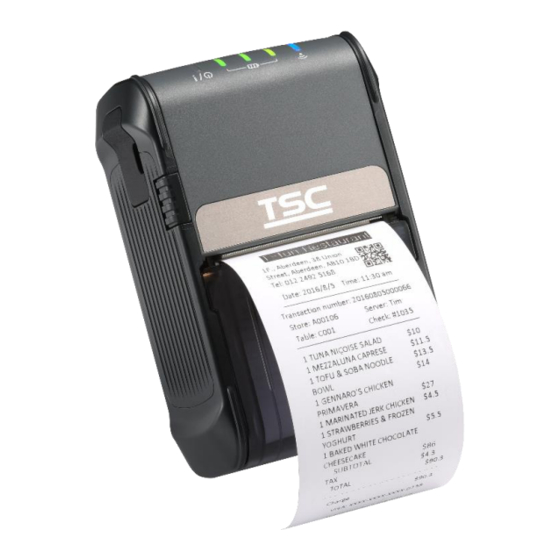
TSC Alpha-2R Service Manual
Direct thermal portable printer
Hide thumbs
Also See for Alpha-2R:
- Manual (56 pages) ,
- User manual (50 pages) ,
- Programming manual (434 pages)
Table of Contents
Advertisement
Quick Links
Advertisement
Table of Contents

Related Manuals for TSC Alpha-2R


Summary of Contents for TSC Alpha-2R
- Page 1 Alpha-2R Direct Thermal Portable Printer SERVICE MANUAL...
-
Page 2: Table Of Contents
Contents 1. FUNDAMENTAL OF THE SYSTEM ........2 1.1 Overview ......................2 2. ELECTRONICS ..........4 2.1 Summary of Board Connectors ..............4 3. MECHANISM ..........11 3.1 Replacing the Platen Roller Assembly ............11 3.2 Replacing the Linerless Platen Roller Assembly ........12 3.3 Replacing the 1"... -
Page 3: Fundamental Of The System
1. FUNDAMENTAL OF THE SYSTEM 1.1 Overview Front View roll Media cover Platen roller LED indicator Feed/Pause button Power on/off button Interface cover Media cover release button Tear bar Black mark sensor Print head USB interface Power jack... - Page 4 Rear View Li-ion battery Battery open clasp Printer serial number label Belt chip...
-
Page 5: Electronics
2. ELECTRONICS 2.1 Summary of Board Connectors Main board top CON6 CON5 CON12 CON1 CON3 CON2 CON11 DCIN1 CON9 Connector Description DC Jack Description DCIN1... - Page 6 Connector Description Firmware download Description 3.3V Data0 Data1 Data2 CON1 Data3 Clock Command USB&RS-232 Description VBUS CON2...
- Page 7 Connector Description Wi-Fi module: Description 3.3V 3.3V 3.3V Reset SPI (MISO) SPI (RTS) SPI (MOSI) SPI (CTS) Interrupt SPI (Clock) Mode: High : BT/Low : Wi-Fi Bluetooth module: CON3 Description 3.3V 3.3V 3.3V Reset UART (RX) UART (RTS) UART (TX) UART (CTS) Configurable Functional GPIO...
- Page 8 Connector Description Head open sensor Description CON5 Head open sensor receiver Black mark sensor Description 3.3V Black mark sensor emitter CON6 Black mark sensor receiver 3.3V LED Board Description VDDBU_3.3V LED Wi-Fi (Green) LED Bluetooth (Blue) LED Wi-Fi/Bluetooth (White) LED Charge status (Red) LED Battery capacity (Green) LED Battery capacity (Green) CON9...
- Page 9 Connector Description Print head Description Data output /Latch Clock TPH 3.3V Strobe1 Strobe2 Strobe3 CON12 /AEO1 /AEO2 Strobe4 Strobe5 Strobe6 Data input...
- Page 10 Connector Description Stepping motor Description CON11 Main board bottom CON8 CON14 CON13...
- Page 11 Connector Description Battery CON13: Description Battery positive Battery positive CON13 CON14 CON14: Description Battery negative Battery negative NFC Module Description 3.3V Interrupt I2C (Data) CON8 I2C (Clock) Reset Firmware download control 3.3V 3.3V...
-
Page 12: Mechanism
3. MECHANISM 3.1 Replacing the Platen Roller Assembly 1. Open the printer cover by pressing the media release button. 2. Use a Phillips screwdriver to remove two screws on platen roller assembly. 3. Replace the platen roller assembly. 4. Reassemble the parts in the reverse procedures. -
Page 13: Replacing The Linerless Platen Roller Assembly
3.2 Replacing the Linerless Platen Roller Assembly 1. Open the printer cover by pressing the media release button. 2. Use a Phillips screwdriver to remove two screws on platen roller assembly. 3. Replace the linerless platen roller assembly. 4. Reassemble the parts in the reverse procedures. -
Page 14: Replacing The 1" / 2" Paper Core Adapter
3.3 Replacing the 1" / 2" paper core adapter 1. Use hex wrench (#9) to remove four screws on lower cover. 2. Remove the right and left side covers by rotating the covers as shown below. Replace the adapters on both sides of paper core. (Please note the direction shown as below) - Page 15 Fix the screws on the adapters with both sides as indicated. Complete the installation of 1" / 2" paper core adapter. 1" / 2" paper core with spindle installed Reassemble the parts in the reverse procedures.
-
Page 16: Replacing The Nfc Module
3.4 Replacing the NFC module Use hex wrench (#9) to remove two screws on lower cover. 2. Remove the left side cover by rotating the cover as shown below. 3. Unplug the flat cable on the slot as indicated. NFC module cable slot... - Page 17 4. Replace the NFC module. (Please place the NFC module on the edge of rib as indicated.) The rib 5. Reassemble the parts in the reverse procedures.
-
Page 18: Replacing The Led & Keys Panel Board
3.5 Replacing the LED & Keys Panel Board 1. Use hex wrench (#9) to remove four screws on lower cover. 2. Remove the right and left side covers by rotating the covers as shown below. 3. Open the printer cover by pressing the media release bar as shown. - Page 19 4. Remove the two screws on both side of the printer. 5. Peel off the waterproof labels on two sides of printer. Waterproof label Waterproof label 6. Disconnect the flat cable on the main board. Remove the top cover assembly.
- Page 20 7. Remove two screws on top cover assembly to replace the LED & keys panel board. LED & keys panel board 8. Reassemble the parts in the reverse procedures.
-
Page 21: Replacing The Gear Assembly & Stepping Motor
3.6 Replacing the Gear Assembly & Stepping Motor 1. Refer to section 3.2 to remove the right, left side and top covers. 2. Remove the plastic plug (black) securing the gears at the top. 3. Remove/Replace the gears assembly. Plastic plug 4. -
Page 22: Replacing The Wi-Fi/Bluetooth Module
3.7 Replacing the Wi-Fi/Bluetooth Module 1. Refer to section 3.2 to remove the right, left side and top covers. 2. Remover four screws securing the internal mechanism. 3. Disconnect the flat cable on the Wi-Fi/Bluetooth control board. (For Wi-Fi module, disconnect the antenna connector on the Wi-Fi module.) Remove/Replace the Wi-Fi/Bluetooth module. -
Page 23: Replacing The Main Board Assembly
3.8 Replacing the Main Board Assembly Refer to section 3.4 to remove the Wi-Fi or Bluetooth module. Remove a screw on the main board. Disconnect all the connectors on the main board. (For TPH connector, loosen the connector lock (black) then disconnect the flat cable from the main board.) Replace the main board. - Page 24 Note: If installing Wi-Fi module, please check the Wi-Fi signal band on configuration page for your using region after replacing the main board. If any questions, please contact the Customer Service Department of your purchased reseller or distributor for assistance. 5.
-
Page 25: Replacing The Print Head Assemble
3.9 Replacing the Print Head Assemble Refer to section 3.5 to remove the main board, take out the internal mechanism as shown below. Loose both side tabs of print head module by pressing the bracket as shown below. 3. Replace the print head module. - Page 26 Note: Please insert the springs into the boss first to install print head module. Reassemble the parts in the reverse procedures.
-
Page 27: Replacing The Hand Open Sensor Assemble
3.10 Replacing the Hand Open Sensor Assemble 1. Refer to section 3.5 to remove the main board. Disconnect the hand open sensor connector on main board. 2. Remove a screw to replace the hand open sensor assembly. 3. Reassemble the parts in the reverse procedures. -
Page 28: Replacing The Black Mark Sensor Assembly
3.11 Replacing the Black Mark Sensor Assembly 1. Refer to section 3.5 to remove the main board. Disconnect the black mark sensor connector on main board. 2. Remove a screw to replace the black mark sensor assembly. 3. Reassemble the parts in the reverse procedures. -
Page 29: Troubleshooting
4. TROUBLESHOOTING 4.1 Common Problems The following guide lists the most common problems that may be encountered when operating this bar code printer. If the printer still does not function after all suggested solutions have been invoked, please contact the Customer Service Department of your purchased reseller or distributor for assistance. - Page 30 * The printer is in Hex Dump * Turn off and on the printer to skip the mode. Irregular printing dump mode. * The RS-232 setting is * Re-set the Rs-232 setting. incorrect.
-
Page 31: Maintenance
5. MAINTENANCE This session presents the clean tools and methods to maintain your printer. 1. Please use one of following material to clean the printer. Cotton swab Lint-free cloth Vacuum / Blower brush 100% ethanol 2. The cleaning process is described as following, Printer Part Method Interval... -
Page 32: Revise History
Revise History Date Content Editor Add Ch.3.2 Replacing the Linerless Platen Roller Assembly Kate 2018/1/19 Add Ch.3.3 Replacing the 1" / 2" paper core adapter Add Ch.3.4 Replacing the NFC module... - Page 34 9F., No.95, Minquan Rd., Xindian Dist., No.35, Sec. 2, Ligong 1st Rd., Wujie Township, New Taipei City 23141, Taiwan (R.O.C.) Yilan County 26841, Taiwan (R.O.C.) TEL: +886-2-2218-6789 TEL: +886-3-990-6677 FAX: +886-2-2218-5678 FAX: +886-3-990-5577 Web site: www.tscprinters.com E-mail: printer_sales@tscprinters.com TSC Auto ID Technology Co., Ltd. tech_support@tscprinters.com...
Need help?
Do you have a question about the Alpha-2R and is the answer not in the manual?
Questions and answers