
Related Manuals for S&T kontron COMe-bV26


Summary of Contents for S&T kontron COMe-bV26
- Page 1 USER GUIDE COMe-bV26 Rev. 1.0, User Guide Doc. ID: 1068 6561 www.kontron.com // 1...
- Page 2 COMe-bV26 - Rev. 1.0, User Guide This page has been intentionally left blank www.kontron.com // 2...
- Page 3 COMe-bV26 - Rev. 1.0, User Guide COME-BV26 – USER GUIDE Disclaimer Kontron would like to point out that the information contained in this user guide may be subject to alteration, particularly as a result of the constant upgrading of Kontron products. This document does not entail any guarantee on the part of Kontron with respect to technical processes described in the user guide or any product characteristics set out in the user guide.
- Page 4 COMe-bV26 - Rev. 1.0, User Guide Intended Use THIS DEVICE AND ASSOCIATED SOFTWARE ARE NOT DESIGNED, MANUFACTURED OR INTENDED FOR USE OR RESALE FOR THE OPERATION OF NUCLEAR FACILITIES, THE NAVIGATION, CONTROL OR COMMUNICATION SYSTEMS FOR AIRCRAFT OR OTHER TRANSPORTATION, AIR TRAFFIC CONTROL, LIFE SUPPORT OR LIFE SUSTAINING APPLICATIONS, WEAPONS SYSTEMS, OR ANY OTHER APPLICATION IN A HAZARDOUS ENVIRONMENT, OR REQUIRING FAIL-SAFE PERFORMANCE, OR IN WHICH THE FAILURE OF PRODUCTS COULD LEAD DIRECTLY TO DEATH, PERSONAL INJURY, OR SEVERE PHYSICAL OR ENVIRONMENTAL DAMAGE (COLLECTIVELY, “HIGH RISK...
- Page 5 COMe-bV26 - Rev. 1.0, User Guide Revision History Revision Brief Description of Changes Date of Issue Author Initial version 2022-Jan-31 Terms and Conditions Kontron warrants products in accordance with defined regional warranty periods. For more information about warranty compliance and conformity, and the warranty period in your region, visit http://www.kontron.com/terms- and-conditions.
-
Page 6: Symbols
COMe-bV26 - Rev. 1.0, User Guide Symbols The following symbols may be used in this user guide DANGER indicates a hazardous situation which, if not avoided, will result in death or serious injury. WARNING indicates a hazardous situation which, if not avoided, could result in death or serious injury. -
Page 7: For Your Safety
COMe-bV26 - Rev. 1.0, User Guide For Your Safety Your new Kontron product was developed and tested carefully to provide all features necessary to ensure its compliance with electrical safety requirements. It was also designed for a long fault-free life. However, the life expectancy of your product can be drastically reduced by improper treatment during unpacking and installation. -
Page 8: Lithium Battery Precautions
COMe-bV26 - Rev. 1.0, User Guide Lithium Battery Precautions If your product is equipped with a lithium battery, take the following precautions when replacing the battery. Danger of explosion if the battery is replaced incorrectly. Replace only with same or equivalent battery type recommended by the manufacturer. ... -
Page 9: Table Of Contents
COMe-bV26 - Rev. 1.0, User Guide Table of Contents Symbols ..........................................6 For Your Safety ........................................7 High Voltage Safety Instructions .................................. 7 Special Handling and Unpacking Instruction ............................7 Lithium Battery Precautions ..................................8 General Instructions on Usage ..................................8 Quality and Environmental Management .............................. - Page 10 COMe-bV26 - Rev. 1.0, User Guide 2.5.4. Operating without Kontron Heatspreader Plate (HSP) Assembly ..................30 2.5.5. Temperature Sensors ..................................31 2.5.6. On-Module Fan Connector ................................32 2.6. Environmental Specification................................33 2.7. Compliance ........................................ 34 2.7.1. MTBF ......................................... 34 2.8. Mechanical Specification ..................................36 2.8.1.
-
Page 11: List Of Tables
COMe-bV26 - Rev. 1.0, User Guide 6.5.2. Exiting the uEFI Shell ................................... 89 6.6. uEFI Shell Scripting ....................................90 6.6.1. Startup Scripting ....................................90 6.6.2. Create a Startup Script ..................................90 6.6.3. Example of Startup Scripts ................................90 6.7. Firmware Update ..................................... 90 Technical Support .................................... - Page 12 COMe-bV26 - Rev. 1.0, User Guide Figure 5: Fan Connector 3-Pin ..................................32 Figure 6: MTBF De-rating Values ................................35 Figure 7: Module Dimensions ..................................36 Figure 8: Module and Carrier Height ................................. 37 Figure 9: Cooling Concept Dimensions ..............................37 Figure 10: COM-bV26 Bottom Side ................................
-
Page 13: 1/ Introduction
COMe-bV26 - Rev. 1.0, User Guide 1/ Introduction This user guide describes the COMe-bV26 module made by Kontron and focuses on describing the modules special features. Kontron recommends users to study this user guide before powering on the module. 1.1. Product Description The COMe-bV26 is a basic form factor COM Express®... -
Page 14: Product Naming Clarification
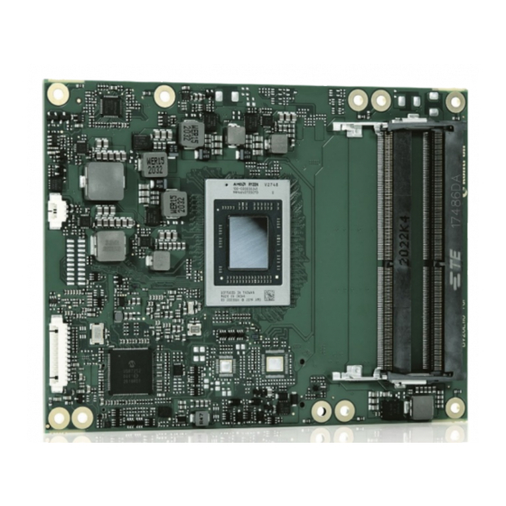
COMe-bV26 - Rev. 1.0, User Guide Figure 2: COM-bV26 Rear Side COMe interface connectors (X1A) SATA mux GBE0- Ethernet Controller Hardware Monitor (HWM) COMe interface connectors (X1B) NVME (optional) Embedded controller TPM 2.0 PCIe switch 10 SPI-Flash (BIOS/EFI) 11 Second SPI Flash (optional) 1.2. -
Page 15: Com Express® Documentation
COMe-bV26 - Rev. 1.0, User Guide Memory size Memory module (#G) /eMMC pseudo SLC memory (#S) 1.3. COM Express® Documentation The COM Express® specification defines the COM Express® module form factor, pinout and signals. For more information about the COM Express® specification, visit the PCI Industrial Computer Manufacturers Group (PICMG®) website. - Page 16 COMe-bV26 - Rev. 1.0, User Guide computer technology evolves. A properly designed COM Express® carrier board can work with several successive generations of COM Express® modules. A COM Express® carrier board design has many advantages of a customized computer-board design and, additionally, delivers better obsolescence protection, heavily reduced engineering effort, and faster time to market www.kontron.com // 16...
-
Page 17: 2/ Product Specification
COMe-bV26 - Rev. 1.0, User Guide 2/ Product Specification 2.1. Module Variants The COMe-bV26 is available in different processor, memory and temperature variants to cover demands in performance, price and power. The following tables list the module variants for the temperature grades. 2.1.1. - Page 18 COMe-bV26 - Rev. 1.0, User Guide Part Number Memory Description 97020-0432-BV26 DDR4-3200 SODIMM 4GB_BV26 DDR4-3200 4 GByte, no ECC 97020-0832-BV26 DDR4-3200 SODIMM 8GB_BV26 DDR4-3200 8 GByte, no ECC 97020-1632-BV26 DDR4-3200 SODIMM 16GB_BV26 DDR4-3200 16 GByte, no ECC 97020-3232-BV26 DDR4-3200 SODIMM 32GB_BV26 DDR4-3200 32 GByte, no ECC 97030-0432-BV26 DDR4-3200 SODIMM 4GB ECC_BV26...
-
Page 19: Functional Specification
COMe-bV26 - Rev. 1.0, User Guide 2.3. Functional Specification 2.3.1. Block Diagram Figure 3: Block Diagram COMe-bV26 COM Express® connector CD – Pin-out Type 6 DP(++) PEG #0-7 DDR4 SODIMM ECC/non-ECC USB #0 (USB3.1) eDP2 LVDS USB #1-3 AMD Embedded V-Series (USB3.1) DDR4 SODIMM V2000 SoCs... -
Page 20: Fusion Controller Hub (Fch)
COMe-bV26 - Rev. 1.0, User Guide The following table lists the specification of the COMe-bV26 processor variants. Table 4: AMD Embedded V-Series Processor Product Family AMD Embedded V2748 V2718 V2546 V2516 V-Series ZEN2 # of Cores # of Threads Base Frequency 2.9 GHz 1.7 GHz 3.0 GHz... -
Page 21: System Memory
COMe-bV26 - Rev. 1.0, User Guide 2.3.4. System Memory The COMe-bV26 supports up to 64 GByte of SODIMM memory with dual DDR4-3200. System Memory Description Socket 2x DDR4 SODIMM Type DDR4-3200 ECC Size (Max.) 64 GByte (2x32 GByte) Technology Dual channel Memory Speed 3200 MTs (max.) In-band ECC... -
Page 22: Audio
COMe-bV26 - Rev. 1.0, User Guide Kontron recommends only using a DP-to-HDMI or DP-to-DVI passive adapter that is complaint to the DP Dual-Mode standard. If adapters are used with FET level shifter for DCC translation, display detection issues may occur. To increase link margin, at 4K resolution a DP redriver on the carrier is recommended 2.3.6. -
Page 23: Pci Express Graphics 3.0 (Peg)
COMe-bV26 - Rev. 1.0, User Guide 2.3.8. PCI Express Graphics 3.0 (PEG) The following table lists the supported PCI Express Graphics (PEG) lane configurations. COMe GPP Lane # Supported Lane Configuration Connector PEG_0 x4 (option) PEG_1 PEG_2 PEG_3 PEG_4 x4 (option) PEG_5 PEG_6 PEG_7... -
Page 24: Sata Gen 3.0
COMe-bV26 - Rev. 1.0, User Guide 2.3.10. SATA Gen 3.0 The COMe-bV26 supports up to two SATA (6 Gb/s) lanes, [SATA_0 and SATA_1]. Alternatively, using a multiplexer IC two SATA (6 Gb/s) lanes [SATA_2 and SATA_3] may be connected to the COMe pinout. The following table lists the SATA port connections. -
Page 25: Storage
COMe-bV26 - Rev. 1.0, User Guide 2.3.12. Storage The following table lists the storage features: Storage Description NVMe SSD 1x up to 1 TByte NVMe SSD NAND Flash (option) Embedded EEPROM (Eeep) 1x Eeep (EEPROM available on I2C bus, address A0h) 2.3.13. -
Page 26: Electrical Specification
COMe-bV26 - Rev. 1.0, User Guide 2.4. Electrical Specification The module powers on by connecting to a carrier board via the COMe interface connector. Before connecting the module to the carrier board, ensure that the carrier board is switch off and disconnected from the main power supply at the time of connection. -
Page 27: Power Management
COMe-bV26 - Rev. 1.0, User Guide 2.4.1.1. Power Supply Voltage Rise Time The input voltage rise time is 0.1 ms to 20 ms from input voltage ≤10% to nominal input voltage. To comply with the ATX specification there must be a smooth and continuous ramp of each DC input voltage from 10 % to 90 % of the DC input voltage final set point. -
Page 28: Power Supply Modes
COMe-bV26 - Rev. 1.0, User Guide COMe Signal Description Reset Button When the “SYS_RESET# “pin is detected active (falling edge triggered), it allows the processor to perform a “graceful” reset, by waiting up to 25 ms for the SMBus (SYS_RESET#) to enter the idle state before forcing a reset, even though activity is still occurring. -
Page 29: Table 8: Single Power Supply Mode Settings
COMe-bV26 - Rev. 1.0, User Guide 2.4.3.2. Single Power Supply Mode To start the module in single power supply mode, connect VCC power and open PWR-OK at the high level. VCC can be 8.5 V to 20 V. To power on the module from S5 state, press the power button or reconnect VCC. Table 8: Single Power Supply Mode Settings State PWRBTN#... -
Page 30: Thermal Management
COMe-bV26 - Rev. 1.0, User Guide 2.5. Thermal Management 2.5.1. Heatspreader Plate Assembly A heatspreader plate (HSP) assembly is NOT a heat sink. The heatspreader plate works as a COM Express® standard thermal interface to be used in conjunction with a heat sink or external cooling devices. External cooling must be provided to maintain the heatspreader plate at proper operating temperatures. -
Page 31: Temperature Sensors
COMe-bV26 - Rev. 1.0, User Guide 2.5.5. Temperature Sensors The on-module thermal resistors measure the processor’s temperature. The thermal resistors are not capable of measuring very fast rises and falls in temperature and measurements may show a certain non-linearity. The thermal resistors give a general indication of the ambient temperature close to the processor. -
Page 32: On-Module Fan Connector
COMe-bV26 - Rev. 1.0, User Guide 2.5.6. On-Module Fan Connector The fan connector powers, controls and monitors an external fan. To connect a standard 3-pin connector fan to the module, use Kontron’s fan cable, see Table 3: Accessories. Figure 5: Fan Connector 3-Pin 3-pin fan connector Table 10: Fan Connector (3-Pin) Pin Assignment Signal... -
Page 33: Environmental Specification
COMe-bV26 - Rev. 1.0, User Guide 2.6. Environmental Specification The COMe-bV26 supports two temperature grades commercial and extended (E1). For temperature grade information, see Chapter 2.1: Module Variants. Table 11: Environmental Specifications Environmental Description Commercial Operating 0°C to +60°C (32°F to 140°F) Grade Non-operating -30°C to +85°C (-22°F to 185°F) -
Page 34: Compliance
COMe-bV26 - Rev. 1.0, User Guide 2.7. Compliance The COMe-bV26 complies with the following or the latest status thereof. If modified, the prerequisites for specific approvals may no longer apply. For more information, contact Kontron Support. Table 12: CE Compliance Europe –... -
Page 35: Figure 6: Mtbf De-Rating Values
COMe-bV26 - Rev. 1.0, User Guide The Telcordia calculation used is “Method 1 Case 3” in a ground benign, controlled environment. This particular method takes into account varying temperature and stress data and the system is assumed to have not been burned- in. -
Page 36: Mechanical Specification
COMe-bV26 - Rev. 1.0, User Guide 2.8. Mechanical Specification The COMe-bV26 is compliant with the COM Express® PICMG COM.0 Rev 3.0, mechanical specification. 2.8.1. Module Dimensions The COMe basic module dimensions are 95 mm x 125 mm (3.7“x 4.9“). Figure 7: Module Dimensions All dimensions are in mm. -
Page 37: Cooling Concept Dimensions
COMe-bV26 - Rev. 1.0, User Guide Figure 8: Module and Carrier Height 13 mm +/- 0.65 mm Heatspreader Heatspreader standoff(s) Module PCB board Connector standoff(s) 5 mm or 8 mm Carrier PCB board 13 mm +/- 0.65 mm 2.8.3. Cooling Concept Dimensions Thermal paste is used to enhance heat transfer away from the APU. -
Page 38: 3/ Features And Interfaces
COMe-bV26 - Rev. 1.0, User Guide 3/ Features and Interfaces 3.1. ACPI Power States ACPI enables the system to power down and save power when not required (suspend) and wake up when required (resume). The ACPI controls the power states S0-S5, where S0 has the highest priority and S5 the lowest priority. The COMe-bV26 supports the ACPI 6.0 power states S0, S3, S4 and S5 only. -
Page 39: Hardware Monitor (Hwm)
COMe-bV26 - Rev. 1.0, User Guide 3.4. Hardware Monitor (HWM) The Nuvoton NCT7802Y Hardware Monitor (HWM) controls the health of the system by monitoring critical aspects such as the module’s processor temperature using thermal resistors, power supply voltages and fan speed for cooling. -
Page 40: Booting The Spi Flash Chip
COMe-bV26 - Rev. 1.0, User Guide Table 16: SPI Boot Pin Configuration BIOS_DIS0# BIOS_DIS1# Boot Bus Function Open Open Boot on on-module SPI Open Boot on carrier board SPI The BIOS cannot be split between two chips. Booting takes place either from the module SPI Flash chip or from the carrier board SPI Flash chip. -
Page 41: Uart
COMe-bV26 - Rev. 1.0, User Guide Each TPM contains an RSA key pair called the Endorsement Key (EK). The pair is maintained inside the TPM and cannot be accessed by software. The Storage Root Key (SRK) is created when a user or administrator takes ownership of the system. -
Page 42: Watchdog Timer Signal
COMe-bV26 - Rev. 1.0, User Guide 3.11.1. Watchdog Timer Signal The watchdog interrupt (WDT) on COM Express® pin B27 on COM Express® connector indicates a Watchdog time-out event has not been triggered within a set time. The WDT signal is configurable to any of the two stages. After reset, the signal is automatically de-asserted. -
Page 43: 4/ System Resources
COMe-bV26 - Rev. 1.0, User Guide 4/ System Resources 4.1. I2C Bus The following table specifies the devices connected to the accessible I2C bus including the I2C address. The I2C bus is available at the COM Express® connector pin A83, I2C_CK and pin A84, I2C_DAT. Table 19: I2C Bus Port Address 8-bit Address 7-bit Address... -
Page 44: 5/ Come Interface Connector
COMe-bV26 - Rev. 1.0, User Guide 5/ COMe Interface Connector The COMe-bV26 is a COM Express® basic module containing two 220-pin connectors X1A and X1B; each with two rows called row A & B on the primary connector X1A and row C & D on the secondary connector X1B. Figure 10: COM-bV26 Bottom Side COMe interface connector (X1A) Pin X1A, PinA1... -
Page 45: X1A And X1B Signals
COMe-bV26 - Rev. 1.0, User Guide 5.2. X1A and X1B Signals For a description of the terms used in the X1A and X1B pin assignment tables, see Table 21: General Signal Description. If a more detailed pin assignment description is required, refer to the PICMG COM.0 Rev. 3.0 Type 6 standard. The information provided under type, module terminations and comments is complimentary to the COM.0 Rev 2.1 Type 6 standard. -
Page 46: Come Interface Connector (X1A) Pin Assignment
COMe-bV26 - Rev. 1.0, User Guide 5.3. COMe Interface Connector (X1A) Pin Assignment The following tables list the pin assignment of the 220-pin connector X1A (A1 to A110) and (Row B1 to B110) and connector X1B (C1 to C110) and (Row D1 to D110). 5.4. - Page 47 COMe-bV26 - Rev. 1.0, User Guide Signal Description Type Termination Comment BATLOW# Battery Low I-3.3 PU 10K 3.3V Assertion will prevent (S5) wake from S3-S5 state SATA_ACT# Serial ATA activity LED OD-3.3 PU 10k 3.3V (S0) HDA_SYNC HD Audio Sync O-3.3 HDA_RST# HD Audio Reset...
- Page 48 COMe-bV26 - Rev. 1.0, User Guide Signal Description Type Termination Comment GPI0 General Purpose Input 0 I-3.3 PU 100K 3.3V (S0) PCIE_TX4+ PCI Express Lane 4 Transmit + DP-O AC Coupled on Only on PCIe_SW Module Option PCIE_TX4- PCI Express Lane 4 Transmit - DP-O AC Coupled on Only on PCIe_SW...
- Page 49 COMe-bV26 - Rev. 1.0, User Guide Signal Description Type Termination Comment LVDS_A_CK- LVDS Channel A Clock- / EDP DP-O Clock: 20-80MHz Lane 3 Transmit - LVDS_I2C_CK LVDS I2C Clock (DDC) / EDP AUX I/O-3.3 PU 2K2 3.3V (S0) LVDS_I2C_DAT I/O-3.3 LVDS I2C Data (DDC) / EDP AUX PU 2K2 3.3V (S0)
- Page 50 COMe-bV26 - Rev. 1.0, User Guide Signal Description Type Termination Comment A107 VCC_12V_A107 Main Input Voltage (8.5-20V) 8.5- A108 VCC_12V_A108 Main Input Voltage (8.5-20V) 8.5- A109 VCC_12V_A109 Main Input Voltage (8.5-20V) 8.5- A110 GND_A110 Power Ground Do not tie the RSVD pins together. www.kontron.com // 50...
-
Page 51: Connector X1A Row B1 - B110
COMe-bV26 - Rev. 1.0, User Guide 5.5. Connector X1A Row B1 - B110 Table 23: Connector X1A Row B1 to B110 Pin Assignment Signal Description Type Termination Comment Power Ground GBE0_ACT# Ethernet Activity LED LPC_FRAME#/ LPC Frame Indicator / O-3.3 ESPI_CS0 eSPI Master Chip Select 0 LPC_AD0/... - Page 52 COMe-bV26 - Rev. 1.0, User Guide Signal Description Type Termination Comment Watchdog Time-Out event O-3.3 PD 10K HDA_SDIN2 Not Connected HDA_SDIN1 Audio Codec Serial Data in 1 I-3.3 HDA_SDIN0 Audio Codec Serial Data in 0 I-3.3 GND_B31 Power Ground SPKR Speaker O-3.3 I2C_CK...
- Page 53 COMe-bV26 - Rev. 1.0, User Guide Signal Description Type Termination Comment GPO2 General Purpose Output 2 O-3.3 PD 100k PCIE_RX3+ PCI Express Lane 3 Receive + DP-I PCIE_RX3- PCI Express Lane 3 Receive - DP-I GND_B60 Power Ground PCIE_RX2+ PCI Express Lane 2 Receive + DP-I PCIE_RX2- PCI Express Lane 2 Receive -...
- Page 54 COMe-bV26 - Rev. 1.0, User Guide Signal Description Type Termination Comment VGA_GRN Analog Video RGB-GREEN PD 150R Only on VGA Option VGA_BLU Analog Video RGB-BLUE PD 150R Only on VGA Option VGA_HSYNC Analog Video H-Sync O-3.3 Only on VGA Option VGA_VSYNC Analog Video V-Sync O-3.3...
-
Page 55: Connector X1B Row C1 - C110
COMe-bV26 - Rev. 1.0, User Guide 5.6. Connector X1B Row C1 - C110 Table 24: Connectors X1B Row C1 to C110 Signal Description Type Termination Comment GND_C1 Power Ground GND_C2 Power Ground USB_SSRX0- USB Super Speed Receive 0- DP-I/O USB_SSRX0+ USB Super Speed Receive 0+ DP-I/O GND_C5... - Page 56 COMe-bV26 - Rev. 1.0, User Guide Signal Description Type Termination Comment DDI2_CTRLCLK_AU DDI2 CTRLCLK/AUX+ I/O- PD 100K DDI2_CTRLDATA_A DDI2 CTRLDATA/AUX- I/O- PU 100K 3.3V (S0) DDI2 DDC/AUX select I-3.3 PD 1M DDI2_DDC_AUX_SE RSVD_C35 Reserved for future use DDI3_CTRLCLK_AU DDI3 CTRLCLK/AUX+ I/O- PD 100K DDI3_CTRLDATA_A...
- Page 57 COMe-bV26 - Rev. 1.0, User Guide Signal Description Type Termination Comment PEG_RX3+ PCI Express Graphics Receive DP-I Input differential pairs PEG_RX3- PCI Express Graphics Receive DP-I Input differential pairs Reserve for future use RSVD_C63 Reserve for future use RSVD_C64 PEG_RX4+ PCI Express Graphics Receive DP-I Input differential pairs...
- Page 58 COMe-bV26 - Rev. 1.0, User Guide Signal Description Type Termination Comment PEG_RX11- PCI Express Graphics Receive Input differential pairs GND_C90 Power Ground PEG_RX12+ PCI Express Graphics Receive Input differential pairs PEG_RX12- PCI Express Graphics Receive Input differential pairs GND_C93 Power Ground PEG_RX13+ PCI Express Graphics Receive Input differential pairs...
-
Page 59: Connector X1B Row D1 - D110
COMe-bV26 - Rev. 1.0, User Guide 5.7. Connector X1B Row D1 - D110 Table 25: Connectors X1B Row D1 to D110 Signal Description Type Termination Comment GND_D1 Power Ground GND_D2 Power Ground USB_SSTX0- USB Super Speed Transmit 0 - DP-O USB_SSTX0+ USB Super Speed Transmit 0 + DP-O... - Page 60 COMe-bV26 - Rev. 1.0, User Guide Signal Description Type Termination Comment DDI1_PAIR2+ Digital Display Interface Pair 2 + DP-O DDI1_PAIR2- Digital Display Interface Pair 2 - DP-O DDI1_DDC_AUX_SE DDI1 DDC/AUX select I-3.3 PD 1M Reserve for future use RSVD_D35 DDI1_PAIR3+ Digital Display Interface Pair 3 + DP-O DDI1_PAIR3-...
- Page 61 COMe-bV26 - Rev. 1.0, User Guide Signal Description Type Termination Comment PEG_TX4+ PCI Express Graphics Transmit DP-O Output differential pairs PEG_TX4- PCI Express Graphics Transmit DP-O Output differential pairs GND_D67 Power Ground PEG_TX5+ PCI Express Graphics Transmit DP-O Output differential pairs PEG_TX5- PCI Express Graphics Transmit DP-O...
- Page 62 COMe-bV26 - Rev. 1.0, User Guide Signal Description Type Termination Comment PEG_TX12- PCI Express Graphics Transmit Output differential pairs GND_D93 Power Ground PEG_TX13+ PCI Express Graphics Transmit Output differential pairs PEG_TX13- PCI Express Graphics Transmit Output differential pairs GND_D96 Power Ground RSVD_D97 SPI Chip Select PEG_TX14+...
-
Page 63: 6/ Uefi Bios
COMe-bV26 - Rev. 1.0, User Guide 6/ UEFI BIOS 6.1. Starting the uEFI BIOS The COM-bV26 uses a Kontron-customized, pre-installed and configured version of AMI Aptio V BIOS ® based on the Unified Extensible Firmware Interface (uEFI) specification. The uEFI BIOS provides a variety of new and enhanced functions specifically tailored to the hardware features of the COM-bV26. -
Page 64: Getting Help
COMe-bV26 - Rev. 1.0, User Guide The currently active menu and the currently active uEFI BIOS Setup item are highlighted in white. Use the left and right arrow keys to select the Setup menu. Each Setup menu provides two main frames. The left frame displays all available functions and configurable functions are displayed in blue. -
Page 65: Main Setup Menu
COMe-bV26 - Rev. 1.0, User Guide 6.4.1. Main Setup Menu The Main setup menu lists sub-screens and second level sub-screens of the functions supported within the Main setup menu. Figure 12: Main Setup Menu The following table shows the Main Menu sub-screens and describes the function. Default settings are in bold. Table 27: Main Setup Menu Sub-screens and Functions Sub-Screen Description... -
Page 66: Advanced Setup Menu
COMe-bV26 - Rev. 1.0, User Guide 6.4.2. Advanced Setup Menu The Advanced Setup menu lists sub-screens and second level sub-screens of the functions supported within the Advanced setup menu. Setting items, on this screen, to incorrect values may cause system malfunctions. Figure 13: Advanced Setup Menu The following table shows the Advanced sub-screen and describes the function. - Page 67 COMe-bV26 - Rev. 1.0, User Guide Sub-Screen Function Second level Sub-Screen/Description Trusted TPM 2.0 UEFI Spec Select the TCG2 Spec Version support. Computing> Version [TCG_1_2, TCG_2] Physical Presence Spec Select to tell OS to support PPI Spec version 1.2 or 1.3. Version Note: Some HCK tests might not support 1.3.
- Page 68 COMe-bV26 - Rev. 1.0, User Guide Sub-Screen Function Second level Sub-Screen/Description Miscellaneous> Sleep Button Mode Shows or hides Lid Switch inside ACPI OS. [Enable, Disable] SMBus Device ACPI Shows or hides SM Bus device from OS. Mode [Hidden, Normal] CPLD Device ACPI Mode Shows or hides CPLD device from OS.
- Page 69 COMe-bV26 - Rev. 1.0, User Guide Sub-Screen Function Second level Sub-Screen/Description Serial Port COM0 (PCI Bus 0, Dev0, Func0, Port0) Console Console Redirection [Enabled, Disabled] Redirection> Console Redirection Settings COM0 (PCI Bus 0, Dev0, Func0, Port0) Console Redirection [Enabled, Disabled] Serial Port for Out-of-Band Management Windows Emergency Management Services (EMS) Console Redirection...
- Page 70 COMe-bV26 - Rev. 1.0, User Guide Sub-Screen Function Second level Sub-Screen/Description [*Active*] Serial Port 1> I0=2E8h: IRQ=3,4,5,7,9,10,11,12] Configuration> Warning: Disabling SIO logical devices may have unwanted side effects. PROCEED WITH CAUTION. [*Active*] Serial Port 2> Serial Port 1 Configuration User this Device [Enabled, Disabled] Logical Device Settings: Current...
- Page 71 COMe-bV26 - Rev. 1.0, User Guide Sub-Screen Function Second level Sub-Screen/Description PCI Subsystem SR-IOV Support SR-IOV capable devices single root IO virtualization support Settings> [Enabled, Disabled] BME DMA Mitigation Re-enables Bus Master Attribute disabled during PCI enumeration for PCI bridges after SMM Locked [Enabled, Disabled] Warning: Changing PCI devices(s) settings may have unwanted side effects! System may hang!
- Page 72 COMe-bV26 - Rev. 1.0, User Guide Sub-Screen Function Second level Sub-Screen/Description Demo Board> PCI-E Port> Hotplug Mode NB Root port Hotplug mode control Dev# (*)/ [Disabled, Hotplug Basic, Hotplug Server, Fun# (*) Hotplug Enhanced, Hotplug Inboard, Auto] Performance> Custom Core PStates AMD CBS>...
- Page 73 COMe-bV26 - Rev. 1.0, User Guide Sub-Screen Function Second level Sub-Screen/Description CPU Common Options> AMD CBS> SMU and PSP Specific uncorrected errors detected by the Debug Mode PSP FW or SMU FW will hang and not reset the system. [Enabled, Disabled, Auto] PPIN Opt-IN Turn on PPIN Feature.
- Page 74 COMe-bV26 - Rev. 1.0, User Guide Sub-Screen Function Second level Sub-Screen/Description DF Common Options> AMD CBS> DF C-States Enable: FW programs registers required to enable feature. [Enabled, Disabled, Auto] DRAM Timing Configuration UMC Common DDR4 Common Options> Options> Warning: Damage caused by use of your AMD Processor outside of specification or in excess of factory settings are not covered under your AMD product warranty and may...
- Page 75 COMe-bV26 - Rev. 1.0, User Guide Sub-Screen Function Second level Sub-Screen/Description UMC Common DDR4 Common Common RAS> AMD CBS> Max Write CRC Error Reply Options> Options> Disable Memory Error Injection [True, False] DRAM ECC Config.> Symbol Size [x4, x8, Auto] DRAM ECC Enable [Enabled,...
- Page 76 COMe-bV26 - Rev. 1.0, User Guide Sub-Screen Function Second level Sub-Screen/Description UMC Common Memory MBIST> Data Eye> 3 Aggressor Channels, AMD CBS> Options> 7 Aggressor Channels] Aggressor Static Lane Control [Enabled, Disabled] Target Static Lane Control [Enabled, Disabled] Data Eye Type [1D Voltage Sweep, 1D Timing Sweep, 2D Full Data Eye, Worst Case Margin...
- Page 77 COMe-bV26 - Rev. 1.0, User Guide Sub-Screen Function Second level Sub-Screen/Description NBID Common SMU Common AMD CBS> System STT Control Options> Options> Temperature [Manual, Auto] Tracking STAPM STAPM Control Control [Manual, Auto] SmartShift Control SmartShift Control [Manual, Auto] System Configuration [10W POR Config–1 Commercial/Consumer, 15W POR Config–1 Commercial/Consumer, 25W POR Config–1 Commercial/Consumer,...
- Page 78 COMe-bV26 - Rev. 1.0, User Guide Sub-Screen Function Second level Sub-Screen/Description AMD CBS> FCH Common Options> Combo PHY Controller 1 COMBO PHY Configuration Static Static Config. Options> Configuration> [Type C, USB Only, DP, USB + DP, Auto] AC Power Loss AC Loss Control Option [Always Off, Always On, Reserved, Previous,...
- Page 79 COMe-bV26 - Rev. 1.0, User Guide Sub-Screen Function Second level Sub-Screen/Description Zero Power ODD [Enabled, Disabled] DT Slot Power Enable [Enabled x1 Lane 0, Enabled x2 Lane0+1, Enabled x4, Disabled] WWAN Power Enable [Enabled, Disabled, Manual] LAN Power Enable [Enabled, Disabled, Manual] WLAN/WIFI Power [Enabled, Disabled, Manual] Enable...
- Page 80 COMe-bV26 - Rev. 1.0, User Guide Sub-Screen Function Second level Sub-Screen/Description AMD PBS> Touch Pad Support [Under I2C 0 Bus, Under I2C 1 Bus, Under I2C 2 Bus, Under I2C 3 Bus, Disabled] Nfc Support [Under I2C 0 Bus, Under I2C 1 Bus, Under I2C 2 Bus, Under I2C 3 Bus, Disabled] ALS Support [Under I2C 0 Bus, Under I2C 1 Bus, Under I2C 2 Bus, Under I2C 3...
- Page 81 COMe-bV26 - Rev. 1.0, User Guide Sub-Screen Function Second level Sub-Screen/Description AMD PBS> iLA TraceMemoryEN Reserved MMIO Intel(R) Ethernet Read only Field Controller> UEFI Driver, Device name, PCI Device ID, Link Status, MAC Address RAM Disk Disk Memory Type [Boot Service Data, Reserved] Configuration>...
-
Page 82: Chipset Setup Menu
COMe-bV26 - Rev. 1.0, User Guide 6.4.3. Chipset Setup Menu The Chipset Setup menu lists sub-screens and second level sub-screens of the functions supported within the Chipset setup menu. Figure 14: Chipset Setup Menu The following table shows Chipset sub-screens and describes the function. Default settings are in bold. Table 29: Chipset Setup Menu Sub-screens and Functions Function Second level Sub-Screen/Description... - Page 83 COMe-bV26 - Rev. 1.0, User Guide Function Second level Sub-Screen/Description South Bridge> SB Debug SB SATA Debug Aggressive Link PM Capability Configuration> Configuration> [Enabled, Disabled, Auto] Port Multiplier Capability [Enabled, Disabled, Auto] SATA Ports Auto Clock Control [Enabled, Disabled, Auto] SATA Partial State Capability [Enabled, Disabled, Auto] SATA FIS Based Switching...
- Page 84 COMe-bV26 - Rev. 1.0, User Guide Function Second level Sub-Screen/Description [Enabled, Disabled] eDP Port Configuration> Configuration Integrated eDP to [Disabled, Auto] LVDS bridge LFP Resolution [Auto [VGA 640x480 1x18, WVGA 800x480 1x18, SVGA 800x600 1x18 XGA 1024x768 1x18, XGA 1024x768 1x24, WXGA 1280x768 1x24, WXGA 1280x800 1x18, WVGA 1366x768 1x24, WSVGA 1024x600 1x18 WSVGA 1024x600 1x24, WXGA+ 1440x900 2x18, WXGA+ 1440x900 2x24 SXGA 1280x1024 2x18, SXGA 1280x1024 2x24, WSXGA+ 1680x1050 2x18...
-
Page 85: Security Setup Menu
COMe-bV26 - Rev. 1.0, User Guide 6.4.4. Security Setup Menu The security Setup menu lists sub-screens and second level sub-screens of the functions supported within the Figure 15: Security Menu Setup The following table shows the Security sub-screens and describes the function. Default settings are in bold. Table 30: Security Setup Menu Sub-screens and Functions Function Description... - Page 86 COMe-bV26 - Rev. 1.0, User Guide Function Description Secure Boot> Export Secure Boot Variables Copy NVRAM content of secure Boot variable to file in a root folder on a file system device. Enroll Efi Image Allow the image to run in secure boot mode. Enroll SHA256 Hash certificate of a PE image into Authorized Signature Database.
-
Page 87: Boot Setup Menu
COMe-bV26 - Rev. 1.0, User Guide 6.4.5. Boot Setup Menu The Boot Setup menu lists sub-screens of the functions supported within the Boot setup menu. Figure 16: Boot Setup Menu The following table shows the Boot Setup sub-screens and describes the function. Default settings are in bold. Table 31: Boot Setup Menu Sub-screens and Functions Function Description... -
Page 88: Save And Exit Setup Menu
COMe-bV26 - Rev. 1.0, User Guide 6.4.6. Save and Exit Setup Menu The Save and Exit Setup menu lists sub-screens of the functions supported within the Save and Exit setup menu. Figure 17: Save and Exit Setup Menu The following table shows the Save and Exit sub-screens and describes the function. Table 32: Save and Exit Setup Menu Sub-screens and Functions Function Description... -
Page 89: The Uefi Shell
COMe-bV26 - Rev. 1.0, User Guide 6.5. The UEFI Shell The Kontron uEFI BIOS features a built-in and enhanced version of the uEFI Shell. For a detailed description of the available standard shell scripting, refer to the EFI Shell User Guide. For a detailed description of the available standard shell commands, refer to the EFI Shell Command Manual. -
Page 90: Uefi Shell Scripting
COMe-bV26 - Rev. 1.0, User Guide 6.6. uEFI Shell Scripting 6.6.1. Startup Scripting If the <ESC> key is not pressed and the timeout has run out, then the uEFI Shell automatically tries to execute some startup scripts. The UEFI shell searches for scripts and executes them in the following order: Initially searches for Kontron flash-stored startup script. -
Page 91: 7/ Technical Support
COMe-bV26 - Rev. 1.0, User Guide 7/ Technical Support For technical support contact our Support department: E-mail: support@kontron.com Phone: +49-821-4086-888 Make sure you have the following information available when you call: Product ID Number (PN), Serial Number (SN) ... -
Page 92: Returning Defective Merchandise
COMe-bV26 - Rev. 1.0, User Guide 7.2. Returning Defective Merchandise All equipment returned to Kontron must have a Return of Material Authorization (RMA) number assigned exclusively by Kontron. Kontron cannot be held responsible for any loss or damage caused to the equipment received without an RMA number. -
Page 93: List Of Acronyms
COMe-bV26 - Rev. 1.0, User Guide List of Acronyms Table 33: List of Acronyms ACPI Advanced Configuration and Power Interface Industry Standard Architecture Application Programming Interface JILI JUMPtec Intelligent LVDS Interface Accelerated Processor Unit KEAPI Kontron Embedded API BIOS Basic Input Output System Local Area Network bits per second Low Pin-Count Interface:... -
Page 94: About Kontron - Member Of The S&T Group
COMe-bV26 – Rev. 1.0, User Guide About Kontron – Member of the S&T Group Kontron is a global leader in IoT/Embedded Computing Technology (ECT). As a part of technology group S&T, Kontron offers a combined portfolio of secure hardware, middleware and services for Internet of Things (IoT) and Industry 4.0 applications.
Need help?
Do you have a question about the kontron COMe-bV26 and is the answer not in the manual?
Questions and answers