
Subscribe to Our Youtube Channel
Related Manuals for S&T Kontron SMARC-sXEL


Summary of Contents for S&T Kontron SMARC-sXEL
- Page 1 USER GUIDE SMARC-sXEL Doc. User Guide Rev. 1.0 Doc. ID: 1068-8367 www.kontron.com // 1...
- Page 2 SMARC-sXEL - User Guide Rev. 1.0 This page has been intentionally left blank www.kontron.com // 2...
- Page 3 SMARC-sXEL - User Guide Rev. 1.0 SMARC-SXEL - USER GUIDE Disclaimer Kontron would like to point out that the information contained in this user guide may be subject to alteration, particularly as a result of the constant upgrading of Kontron products. This document does not entail any guarantee on the part of Kontron with respect to technical processes described in the user guide or any product characteristics set out in the user guide.
- Page 4 SMARC-sXEL - User Guide Rev. 1.0 Intended Use THIS DEVICE AND ASSOCIATED SOFTWARE ARE NOT DESIGNED, MANUFACTURED OR INTENDED FOR USE OR RESALE FOR THE OPERATION OF NUCLEAR FACILITIES, THE NAVIGATION, CONTROL OR COMMUNICATION SYSTEMS FOR AIRCRAFT OR OTHER TRANSPORTATION, AIR TRAFFIC CONTROL, LIFE SUPPORT OR LIFE SUSTAINING APPLICATIONS, WEAPONS SYSTEMS, OR ANY OTHER APPLICATION IN A HAZARDOUS ENVIRONMENT, OR REQUIRING FAIL-SAFE PERFORMANCE, OR IN WHICH THE FAILURE OF PRODUCTS COULD LEAD DIRECTLY TO DEATH, PERSONAL INJURY, OR SEVERE PHYSICAL OR ENVIRONMENTAL DAMAGE (COLLECTIVELY, "HIGH RISK APPLICATIONS").
- Page 5 SMARC-sXEL - User Guide Rev. 1.0 Revision History Revision Brief Description of Changes Date of Issue Author/ Editor Initial version 2021-Sept-17 Terms and Conditions Kontron warrants products in accordance with defined regional warranty periods. For more information about warranty compliance and conformity, and the warranty period in your region, visit http://www.kontron.com/terms- and-conditions.
-
Page 6: Symbols
SMARC-sXEL - User Guide Rev. 1.0 Symbols The following symbols may be used in this user guide DANGER indicates a hazardous situation which, if not avoided, will result in death or serious injury. WARNING indicates a hazardous situation which, if not avoided, could result in death or serious injury. -
Page 7: For Your Safety
SMARC-sXEL – User Guide Rev. 1.0 For Your Safety Your new Kontron product was developed and tested carefully to provide all features necessary to ensure its compliance with electrical safety requirements. It was also designed for a long fault-free life. However, the life expectancy of your product can be drastically reduced by improper treatment during unpacking and installation. -
Page 8: Lithium Battery Precautions
SMARC-sXEL - User Guide Rev. 1.0 Lithium Battery Precautions If your product is equipped with a lithium battery, take the following precautions when replacing the battery. Danger of explosion if the battery is replaced incorrectly. Replace only with same or equivalent battery type recommended by the manufacturer. ... -
Page 9: Table Of Contents
SMARC-sXEL - User Guide Rev. 1.0 Table of Contents Symbols ..........................................6 For Your Safety ........................................7 High Voltage Safety Instructions .................................. 7 Special Handling and Unpacking Instruction ............................7 Lithium Battery Precautions ..................................8 General Instructions on Usage ..................................8 Quality and Environmental Management .............................. -
Page 10: List Of Tables
SMARC-sXEL - User Guide Rev. 1.0 6.8.1. SGMII via SERDES (option) ................................. 34 6.8.2. Link and Activity LEDs ..................................34 SATA 3.0 ........................................34 CAN Bus Interfaces ....................................35 Eeep ..........................................35 eMMC Flash Memory (option) ................................35 I2C Bus Support ...................................... 35 Kontron CPLD ...................................... -
Page 11: List Of Figures
SMARC-sXEL - User Guide Rev. 1.0 Table 3: Component Main Data................................... 20 Table 4: Environmental Conditions ................................25 Table 5: Compliance CE ....................................26 Table 6: Country Compliance ..................................26 Table 7: MTBF ........................................27 Table 8: Power Supply Voltage Requirements ............................28 Table 9: Fan Connector .................................... - Page 12 SMARC-sXEL - User Guide Rev. 1.0 Figure 14: 3-Pin Power Connector ................................29 Figure 15: SMARC Connector 314-Pin ................................ 40 Figure 16: Main Setup Menu ..................................70 Figure 17: Advanced Setup Menu................................72 Figure 18: Chipset Setup Menu ..................................86 Figure 19.
-
Page 13: 1/ Introduction
SMARC-sXEL - User Guide Rev. 1.0 1/ Introduction This user guide describes the Smart Mobility Architecture (SMARC) SMARC-sXEL module, known as module within this user guide and designed for use with a carrier board. The use of this user guide implies a basic knowledge of PC hard- and software. This user guide is focused on describing the special features and is not intended to be a standard PC textbook. -
Page 14: 2/ General Safety Instructions
SMARC-sXEL - User Guide Rev. 1.0 2/ General Safety Instructions Please read this passage carefully and take careful note of the instructions, which have been compiled for your safety and to ensure to apply in accordance with intended regulations. If the following general safety instructions are not observed, it could lead to injuries to the operator and/or damage of the product;... -
Page 15: Electrostatic Discharge (Esd)
SMARC-sXEL - User Guide Rev. 1.0 no cables or parts without insulation in electrical circuits with dangerous voltage or power should be touched directly or indirectly a reliable protective earthing connection is provided a suitable, easily accessible disconnecting device is used in the application (e.g. overcurrent protective device), if the product itself is not disconnectable ... -
Page 16: 3/ Description
SMARC-sXEL - User Guide Rev. 1.0 3/ Description SMARC™ Modules The SMARC™ standard was developed especially for new modules with SOC processors. Modules with this interfaces are characterized by the extremely flat form factor. The SMARC or MXM 3.0 connector comes with 314 pins and a construction height of just 4.3 millimeters. -
Page 17: Variants
SMARC-sXEL - User Guide Rev. 1.0 Variants The SMARC-sXEL module variants are: Table 1: SMARC-sXEL Product Variants Product Number Memory Flash Eth Phy Display SERDES Op Temp. 51016-0432-J2-4 J6426 4 GByte 32 GByte 2x 1 GByte LVDS, HDMI, DP++ 0°C to 60°C 51016-0416-N1-2 N6211 4 GByte... -
Page 18: 4/ System Specification
SMARC-sXEL - User Guide Rev. 1.0 4/ System Specification Functional Block Diagram The block diagram shows all available SMARC-sXEL interfaces. Figure 2: Block Diagram Level- LPDDR4-4267 memory down (up to shifter 16GB – IB-ECC) Intel DP++ Intel® Atom™Embedded Elkhard-Lake Gen11 (DDI1) iGFX (Intel®... -
Page 19: Top Side Features
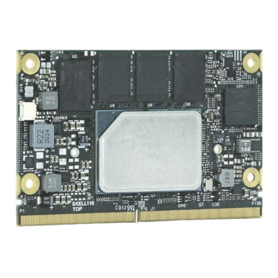
SMARC-sXEL - User Guide Rev. 1.0 Top Side Features Figure 3:Top Side SMARC 2.1 connector 3-pin fan connector Multi-Chip Package (MCP) Mounting points 4x LPDDR memory down Rear Side Features Figure 4: Rear Side SMARC 2.1 connector Product labelling www.kontron.com // 19... -
Page 20: Component Main Data Specification
SMARC-sXEL - User Guide Rev. 1.0 Component Main Data Specification Table 3: Component Main Data SMARC-sXEL Form factor Short module form factor: 82 mm x 50 mm, max. thickness 6 mm Processor Intel® Atom®/Pentium®/Celeron® 6xxx processor family Main Memory Up to 16 GByte LPDDR4 memory down with in-band ECC support Storage (eMMC 5.1 Flash) Up to 128 GByte MLC or option for up to 64 GB pSLC Graphics controller... -
Page 21: Mechanical Specification
SMARC-sXEL - User Guide Rev. 1.0 Mechanical Specification The SMARC short module form factor is 82 mm x 50 mm and includes four mounting holes per SMARC specification. There are two additional holes to enable the attachment of a thermal device such as a heatsink/heatspreader. The total height of the SMARC-sXEL module depends on the height of the implemented cooling solution. -
Page 22: Figure 7: Dimensions Of Smarc-Sxel - Commercial
SMARC-sXEL - User Guide Rev. 1.0 Figure 7: Dimensions of SMARC-sXEL - Commercial Figure 8: Thickness from the Side View, Commercial www.kontron.com // 22... -
Page 23: Thermal Management Specification
SMARC-sXEL - User Guide Rev. 1.0 Thermal Management Specification The SMARC-sXEL uses an on-chip thermal sensors located within the CPU to measure the CPU temperature, and a thermal sensor close to the Hardware monitor chip to measure the module temperature. Figure 9: Temperature Sensors On-chip CPU thermal sensor Hardware monitor chip temperature... -
Page 24: Figure 10: Heatspreader As Cooling Solution
SMARC-sXEL - User Guide Rev. 1.0 Kontron recommends the use of thermal interfaces between the heatspreader plate and the major heat-generating components. About 80 % of the power dissipated within the module is conducted to the heatspreader plate and can be removed by the cooling solution. -
Page 25: Environmental Specification
SMARC-sXEL - User Guide Rev. 1.0 Figure 12: Heatspreader Height for Commercial Variants Environmental Specification Table 4: Environmental Conditions Operating Temperature Commercial grade: 0°C to 60°C Industrial grade: -40°C to +85°C Humidity 93 % relative Humidity at 40 °C, non-condensing (according to IEC 60068-2-78) Storage Temperature Commercial grade: -30°C to +85°C... -
Page 26: Compliance
SMARC-sXEL - User Guide Rev. 1.0 Compliance The SMARC-sXEL complies with the relevant requirements and the approximation of the laws relating to ‘CE’ and the standards that are constitutional parts of the declaration. If modified, the prerequisites for specific approvals may no longer apply. -
Page 27: Mtbf
SMARC-sXEL - User Guide Rev. 1.0 4.8.1. MTBF Table 7: MTBF MTBF System MTBF (hour) = 563867 h @ 40°C for SMARC-sXEL Reliability report article number: 51017-0832-R2-4PRO The MTBF estimated value assumes no fan, but a passive heat sinking arrangement. Estimated RTC battery life (as opposed to battery failures) is not accounted for and needs to be considered separately. -
Page 28: Power Specification
SMARC-sXEL - User Guide Rev. 1.0 Power Specification The SMARC-sXEL powers on by connecting to a carrier board via the SMARC connector. Before connecting the module to the carrier board, ensure that the carrier board is switch off and disconnected from the main power supply at the time of connection. -
Page 29: 5/ Module And Connectors
SMARC-sXEL - User Guide Rev. 1.0 5/ Module and Connectors Connectors Location Figure 13: Connectors (top side) SMARC 2.1 connector 3-pin fan connector SMARC Connector The SMARC connector is the central interface containing pins on the top and bottom sides: ... -
Page 30: 6/ Features And Interfaces
SMARC-sXEL - User Guide Rev. 1.0 6/ Features and Interfaces Processor Support The Intel Atom®/Pentium®/Celeron® 6xxx processor family is the base for the SMARC-sXEL. Table 10: Supported Processors Intel® Celeron® Pentium® Celeron® Pentium® J6413 J6426 N6211 N6415 # of Cores # of Threads Base Frequency 1.8 GHz... -
Page 31: System Memory Support
SMARC-sXEL - User Guide Rev. 1.0 System Memory Support The SMARC-sXEL provides two LPDDR4 banks with two devices per bank. Default LPDDR4 Memory sizes are 4 GByte (2x 16 Gb) and 8 GByte (4x 16 Gb). The memory system has LPDDR4 memory down with in-band ECC support (1-bit correction, 2-bits detection). The module’s integrated memory controller helps improve the safety and reliability by providing ECC protection to specific regions of physical memory space. -
Page 32: Hd Audio Interfaces
SMARC-sXEL - User Guide Rev. 1.0 HD Audio Interfaces The SMARC-sXEL provides two I2S audio interfaces; where one I2S Interface is pin shared with HDA. The second I2S interface can also be implemented as a HDA interface. The HDA signal level is 1.8V. Table 13: HD Audio SMARC Connector PCH Pin... -
Page 33: Usb 2.0 Client Mode
SMARC-sXEL - User Guide Rev. 1.0 Table 17: USB 2.0 Ports SMARC Connector PCH USB Port HSIO Port USB0 USB2_2 USB1 USB2_3 USB2 USB2_0 USB3 USB2_1 Dual role Client / Host USB4 USB2_4 USB5 USB2_5 6.6.1. USB 2.0 Client Mode USB port 3 provides dual role client/host. -
Page 34: Sgmii Via Serdes (Option)
SMARC-sXEL - User Guide Rev. 1.0 Table 19: Ethernet Ports SMARC connector ModPHY Lane HSIO Port Description GBE0_MDI[0-3] ETH0 Gigabit Ethernet Controller 0: Media Dependent Interface Differential Pairs 0, 1, 2, 3. The MDI can operate in 2.5 Gb/s, 1000Mb/s, 100 Mb/s, and 10 Mb/s modes. GBE1_MDI[1-3] ETH1 Gigabit Ethernet Controller 0: Media Dependent Interface... -
Page 35: Can Bus Interfaces
SMARC-sXEL - User Guide Rev. 1.0 CAN Bus Interfaces The CAN BUS communication according to ISO 11898-1 (identical to the Bosch CAN Protocol Specification 2.0 part A, B) and according to ISO 11898-4 (Time-triggered Communication on CAN). The Can Bus controller supports communication according to CAN FD Protocol Specification 1.0. The CAN FD option can be used together with event-triggered CAN communication. -
Page 36: Rtc
SMARC-sXEL - User Guide Rev. 1.0 The embedded controller is responsible for the power sequence and reset control for all components. Table 24: Kontron CPLD PCH PIN CPLD I/O Description GP_G[15:18] / ESPI_IO[0:3] G10, F12, F13, E13 GP_G21 / ESPI_CLK Dedicated clock pin GP_G22 / ESPI_RST0_N GP_G20 / ESPI_CS0_N... -
Page 37: Spi Interfaces
SMARC-sXEL - User Guide Rev. 1.0 SPI Interfaces The Serial Peripheral Interface (SPI) bus is a synchronous serial data link where devices communicate in master/slave mode and the master device initiates the data frame. Multiple slave devices are allowed with individual slave select (chip select) lines. -
Page 38: Uart Interfaces
SMARC-sXEL - User Guide Rev. 1.0 any of the hashed components have been modified since the last start, the match fails, and the system cannot gain entry to the network. The SMARC-sXEL supports the built-in CPU firmware TPM (fTPM) using the integrated TPM 2.0 capability of the Intel Platform Trusted Technology (Intel®... -
Page 39: 7/ Pin Definitions
SMARC-sXEL - User Guide Rev. 1.0 7/ Pin Definitions The following sections provide pin definitions and detailed description of all on-board connectors. The connector definitions follow the following notation. Table 28: Connector Definitions Product Number Description Shows the pin-numbers in the connector. The graphical layout of the connector definition tables is made similar to the physical connectors Signal The mnemonic name of the signal at the current pin. -
Page 40: Pinout Of Smarc Connector (Top Side)
SMARC-sXEL - User Guide Rev. 1.0 Figure 15: SMARC Connector 314-Pin Top side connector pins P[1-156] and on the Connector-key gap reverse side, bottom side connector pins S[1-158] Table 29: SMARC Pinout Legend Signal Description DP-I Differential Pair Input DP-I/O Differential Pair Input/Output I/O-3.3 Bi-directional 3.3 V I/O signal... - Page 41 SMARC-sXEL - User Guide Rev. 1.0 Primary Description Type Termin- Comment ation GBE1_SDP IEEE 1588 Trigger Signal for I/O CMOS Hardware Implementation of 3.3V PTP (Precision Time Protocol) GBE0_SDP IEEE 1588 Trigger Signal for I/O CMOS Hardware Implementation of 3.3V PTP (Precision Time Protocol) CSI1_RX0+ CSI1 differential input (point...
- Page 42 SMARC-sXEL - User Guide Rev. 1.0 Primary Description Type Termin- Comment ation MDI2 B1_D C+/- MDI3 B1_D D+/- GBE0_LINK100# Link Speed Indication LED for O OD CMOS Shall be able to sink 24mA or more GBE0 100Mbps 3.3V Carrier LED current. GBE0_LINK1000 Link Speed Indication LED for O OD CMOS...
- Page 43 SMARC-sXEL - User Guide Rev. 1.0 Primary Description Type Termin- Comment ation MDI3 B1_D D+/- GBE0_MDI1+ Differential Pair Signals for I/O GBE MDI Gigabit Ethernet Controller 0: Media External Transformer Carrier Dependent Interface Differential Pairs 0, Series Termination: 1, 2, 3. The MDI can operate in 1000, 100, Magnetics Module and 10Mbit/sec modes.
- Page 44 SMARC-sXEL - User Guide Rev. 1.0 Primary Description Type Termin- Comment ation SDIO_WP PU 10k SDIO Write Protect. This I OD CMOS signal denotes the state of 1.8V / 3.3V the write-protect tab on SD cards. SDIO_CMD SDIO Command/Response. I/O CMOS SDIO controller may detect SD Cards This signal is used for card 1.8V / 3.3V...
- Page 45 SMARC-sXEL - User Guide Rev. 1.0 Primary Description Type Termin- Comment ation SATA_RX+ I SATA Series AC coupled on Module 10nF Serial ATA Channel 0 Receive Input Differential Pair SATA_RX- Serial ATA Channel 0 Receive I SATA Series AC coupled on Module 10nF Input Differential Pair ESPI_CS0# / ESPI1 Master Chip Select 0...
- Page 46 SMARC-sXEL - User Guide Rev. 1.0 Primary Description Type Termin- Comment ation Carrier OD driver to indicate over- current situation. USB2+ USB Differential Data Pairs I/O USB for Port 2 USB2- I/O USB USB Differential Data Pairs for Port 2 USB2_EN_OC# USB Over-Current Sense for I/O OD...
- Page 47 SMARC-sXEL - User Guide Rev. 1.0 Primary Description Type Termin- Comment ation AC coupled off Module HDMI_D2- / HDMI Port, Differential Pair O TMDS DP1_LANE0- Data Lines HDMI Secondary DP Port O DP AC coupled off Module 100nF DC blocking Differential Pair Data Lines capacitors shall be placed on the Carrier HDMI_D1+ /...
- Page 48 SMARC-sXEL - User Guide Rev. 1.0 Primary Description Type Termin- Comment ation I/O DP 3.3V PD 100k Secondary DP Port. AC coupled on Module. If Bidirectional Channel used DP1_AUX_SEL=0 (DP mode): AC coupled for Link Management and on module, 100k PD. If DP1_AUX_SEL=1 Device Control (HDMI mode): DC coupled, CMOS, 100k PU.
- Page 49 SMARC-sXEL - User Guide Rev. 1.0 Primary Description Type Termin- Comment ation discrepancy between the 1.5V and 1.8V signaling, as the chance of damage in mismatched systems is negligible. GPIO Pin 4 Preferred Output PU 470k Alternative use: HDA_RST# I/O CMOS 1.8V P113 GPIO5 /...
- Page 50 SMARC-sXEL - User Guide Rev. 1.0 Primary Description Type Termin- Comment ation P131 SER0_RTS# O CMOS 1.8V Request to Send Handshake Line for Port 0 P132 SER0_CTS# Clear to Send Handshake Line I CMOS 1.8V for Port 0 P133 P134 SER1_TX Asynchronous Serial Data O CMOS 1.8V...
-
Page 51: Pinout Of Smarc Connector (Bottom Side)
SMARC-sXEL - User Guide Rev. 1.0 7.1.2. Pinout of SMARC Connector (Bottom Side) Table 31: SMARC 2.1 Specification Pinout (bottom side) Secondary Description Type Termin- Comment ation CSI1_TX+ / I2C clock for serial camera I/O OD PU 2.2K MIPI-CSI 2.0 mode uses I2C_CAM1_CK I2C_CAM1_CK data support link or CMOS / O... - Page 52 SMARC-sXEL - User Guide Rev. 1.0 Secondary Description Type Termin- Comment ation appropriate for 10/100/1000 unused in some modes according to the GBE transceivers Carrier following: Parallel Termination: 1000 Secondary side center tap MDI0 B1_D TX+/ TX+/ terminations appropriate for A+/- Gigabit Ethernet implementations...
- Page 53 SMARC-sXEL - User Guide Rev. 1.0 Secondary Description Type Termin- Comment ation Gigabit Ethernet MDI0 B1_D TX+/ TX+/ implementations A+/- MDI1 B1_D RX+/ RX+/ B+/- MDI2 B1_D C+/- MDI3 B1_D D+/- GBE1_MDI2- Differential Pair Signals for I/O GBE MDI Gigabit Ethernet Controller 1: Media External Transformer Carrier Dependent Interface Differential Pairs 0, Series Termination:...
- Page 54 SMARC-sXEL - User Guide Rev. 1.0 Secondary Description Type Termin- Comment ation MDI3 B1_D D+/- GBE1_CTREF Center-Tap Reference Analog 0 to Voltage for Carrier Board 3.3V max Ethernet Magnetic (if required by the Module GBE PHY) PCIE_D_TX+ / Differential PCIe link D O PCIE Series AC coupled on Module 75-265nF SERDES_0_TX+...
- Page 55 SMARC-sXEL - User Guide Rev. 1.0 Secondary Description Type Termin- Comment ation configuration where I/O[1] can be used to signal the Alert event MDIO_CLK O CMOS 1.8V Signal for communication to a PHY MDIO Signals to Configure Possible PHYs MDIO_DAT MDIO Signals to Configure I/O OD PU 1k5...
- Page 56 SMARC-sXEL - User Guide Rev. 1.0 Secondary Description Type Termin- Comment ation discrepancy between the 1.5V and 1.8V signaling, as the chance of damage in mismatched systems is negligible. I2S2 Digital Audio Clock I/O CMOS Module Output if CPU acts in Master 1.8V Mode.
- Page 57 SMARC-sXEL - User Guide Rev. 1.0 Secondary Description Type Termin- Comment ation USB2_SSTX- O USB SS shall Transmit Signal Differential DC blocking capacitors 100nF Pairs for SuperSpeed on Port placed on the Module shall USB2_SSRX+ Receive Signal Differential I USB SS DC blocking capacitors 100nF Pairs for SuperSpeed on Port placed on the Carrier...
- Page 58 SMARC-sXEL - User Guide Rev. 1.0 Secondary Description Type Termin- Comment ation DP0_AUX_SEL Auxiliary Selection I CMOS 1.8V PD 1M Pulled to GND on Carrier for DP operation in Dual Mode (DP++) implementations Module must tolerate high level in stand-by mode. Should be connected to pin 13 of the DisplayPort connector to enable a dual-mode DisplayPort interface.
- Page 59 SMARC-sXEL - User Guide Rev. 1.0 Secondary Description Type Termin- Comment ation O D-PHY Secondary DSI Panel Differential Pair Clock Lines S109 LVDS1_CK- / Secondary LVDS Channel O LVDS 100 ohm differential termination across eDP1_AUX- / Differential Pair Clock Lines the differential pair at the endpoint of DSI1_CLK- the signal path, usually on the display...
- Page 60 SMARC-sXEL - User Guide Rev. 1.0 Secondary Description Type Termin- Comment ation O DP Secondary 4-Lane eDP AC coupled off Module 100nF DC blocking Differential Pair Data Lines capacitors shall be placed on the Carrier. Only in use, when two separate eDP ports are supported.
- Page 61 SMARC-sXEL - User Guide Rev. 1.0 Secondary Description Type Termin- Comment ation O D-PHY Secondary DSI Panel No blocking capacitors or termination Differential Pair Data Lines required. Layout for 90 ohm differential impedance. S122 LCD1_BKLT_PW Secondary LVDS Channel O CMOS 1.8V Through pulse width modulation (PWM) Brightness Control only in use, when two separate LVDS...
- Page 62 SMARC-sXEL - User Guide Rev. 1.0 Secondary Description Type Termin- Comment ation O D-PHY Primary DSI Panel Differential No blocking capacitors or termination Pair Data Lines required. Layout for 90 ohm differential impedance. S130 S131 LVDS0_2+ / Primary LVDS Channel O LVDS 100 ohm differential termination across eDP0_TX2+ /...
- Page 63 SMARC-sXEL - User Guide Rev. 1.0 Secondary Description Type Termin- Comment ation S138 O LVDS LVDS0_3- / Primary LVDS Channel 100 ohm differential termination across eDP0_TX3- / Differential Pair Data Lines the differential pairs at the endpoint of DSI0_D3- the signal path, usually on the display assembly.
- Page 64 SMARC-sXEL - User Guide Rev. 1.0 Secondary Description Type Termin- Comment ation sensitive. Should be de- bounced on the Module. S149 SLEEP# PU 10k Driven by OD on Carrier. Sleep indicator from Carrier I OD CMOS Board. be sourced from 1.8 to 5V user Sleep button or Carrier logic.
- Page 65 SMARC-sXEL - User Guide Rev. 1.0 Secondary Description Type Termin- Comment ation S157 TEST# Held Low by Carrier to Invoke I OD CMOS Module must implement PU but actual Module Vendor Specific Test 1.8 to 5V vendor value is depended on particular Module Functions specific design.
-
Page 66: 8/ Configuration
SMARC-sXEL - User Guide Rev. 1.0 8/ Configuration Boot Select The three pins (BOOT_SEL2# Pin-P125; BOOT_SEL1# pin-P124; BOOT_SEL0#, pin-P123) determine the module’s boot device. The pins are set to be either not connected (Float or pulled to ground), to select the required boot method. Register for Kontron’s Customer Section to get access to BIOS downloads and PCN service. -
Page 67: Watch Dog
SMARC-sXEL - User Guide Rev. 1.0 Open pin P123 (BOOT_SEL0#) and pin P124 (BOOT_SEL1#) and connect pin P125 (BOOT_SEL2#) to ground to enable the external SPI Flash chip to boot on carrier SPI or open pin P123 (BOOT_SEL0#) and pin P124 (BOOT_SEL1#) and pin P125 (BOOT_SEL2#) to enable SPI Flash chip to boot on-module SPI. -
Page 68: Power Button (Power_Btn#)
SMARC-sXEL - User Guide Rev. 1.0 If power is removed, the wake-up event (S0) requires VDD_IN to power on the module. 8.3.2. Power Button (POWER_BTN#) The power button (Pin-P128) is available through the SMARC connector. To start the module using the Power Button the PWRBTN# signal must be at least 50 ms (50 ms ≤... -
Page 69: 9/ Uefi Bios
SMARC-sXEL - User Guide Rev. 1.0 9/ uEFI BIOS Starting the uEFI BIOS The board is provided with a Kontron-customized, pre-installed and configured version of American Megatrends, Inc. (AMI). It is based on the Unified Extensible Firmware Interface (uEFI) specification and the Intel® Platform Innovation Framework for EFI. -
Page 70: Setup Menus
SMARC-sXEL - User Guide Rev. 1.0 Setup Menus The Setup utility features a selection bar at the top of the screen that lists the available menus: Main Advanced Chipset Security Boot Save & Exit The currently active menu and the currently active uEFI BIOS Setup item are highlighted in white. - Page 71 SMARC-sXEL - User Guide Rev. 1.0 Sub-screen Description BIOS BIOS Information, FSP information, PSE information, Board information, Processor information, PCH information, Package information and ME Firmware information Information> System Choose the system default language: Language> [English] Platform Read only field Information>...
-
Page 72: Advanced Setup Menu
SMARC-sXEL - User Guide Rev. 1.0 Advanced Setup Menu The Advanced Setup menu provides sub-screens and second level sub-screens with functions, for advanced configuration and Kontron specific configurations. Setting items, on this screen, to incorrect values may cause system malfunctions. Figure 17: Advanced Setup Menu The following table shows the Advanced sub-screen and describes the function. - Page 73 SMARC-sXEL - User Guide Rev. 1.0 Sub-screen Next Level Sub-screens / Description RC ACPI Low Power S0 Determines If ACPI Lower power S0 idle capability (mutually exclusive Settings> Idle Capability> with Smart Connect). While enabled 8254 timer is disabled for SLP_S0 support.
- Page 74 SMARC-sXEL - User Guide Rev. 1.0 Sub-screen Next Level Sub-screens / Description Power and CPU Power Read only field Performance> Management> P1 to P3 Fused Max Core Ratio Boot Select the performance state that the BIOS will set Performance starting from rest vector. Mode>...
- Page 75 SMARC-sXEL - User Guide Rev. 1.0 Sub-screen Next Level Sub-screens / Description CPU Power View/Configure Power and 2-Core Ratio Range 0 to 83. Minimum range Performance> Management> Turbo Options> Limit Override> varies between processors. This 2-Core ration limit must be less than or equal to 1-Core ratio limit.
- Page 76 SMARC-sXEL - User Guide Rev. 1.0 Sub-screen Next Level Sub-screens / Description Power and CPU Power CPU Lock Overclocking Overclocking lock (Bit 20) in Performance> Management> Configuration> Lock> FLEX_Ratio (194) MSR [Enabled, Disabled] GT- Power RC6 (Render Checks Enable render standby support Management Standby)>...
- Page 77 SMARC-sXEL - User Guide Rev. 1.0 Sub-screen Next Level Sub-screens / Description PCH-FW OEM Key Automatic OEM BIOS automatically sends HECI command to revoke Configuration> Revocation Key Revocation> OEM keys. [Enabled, Disabled] configuration> Invoke OEM Key A Heci command will be sent to revoke OEM key. Revocation>...
- Page 78 SMARC-sXEL - User Guide Rev. 1.0 Sub-screen Next Level Sub-screens / Description Thermal Platform CPU Energy [Enabled, Disabled] Consideration> Thermal Read> Configuration> CPU Temp [Enabled, Disabled] Read> Alert Enable Locks all Alert enable settings. Lock> [Enabled, Disabled] CPU Temp> Fail safe temp that EC uses if OS hangs [72] CPU Fan Speed>...
- Page 79 SMARC-sXEL - User Guide Rev. 1.0 Sub-screen Next Level Sub-screens / Description ACPI D3Cold USB Port 2> USB RTD3 support. Superspeed USB 3.0 exposed as RTD3 capable. Settings> Highspeed: USB 2.0 devices exposed as RTD3 capable. Disabled: USB RTD3 support disabled. For Sawtoothpeak USB port1 (below) is Superspeed and port2(top) is highspeed.
- Page 80 SMARC-sXEL - User Guide Rev. 1.0 Sub-screen Next Level Sub-screens / Description Trusted SHA_384 PCR [Enabled, Disabled] Computing> Bank> SM3_256 PCR [Enabled, Disabled] Bank> Pending Schedule an operating for security device. Note: computer reboots operation> during restart to change the state of security device. [None, Clear] Platform [Enabled, Disabled]...
- Page 81 SMARC-sXEL - User Guide Rev. 1.0 Sub-screen Next Level Sub-screens / Description Miscellaneous> I2C Speed> Speed in KHz (Min. 1 KHz and max. 400 KH). 200 KHz is an appropriate default value. [200] Onboard I2C Selects Multi master or Busclear Mode>...
- Page 82 SMARC-sXEL - User Guide Rev. 1.0 Sub-screen Next Level Sub-screens / Description Smart Settings> Smart Self-test> Runs Smart self-test on all HDDs during Post [Enabled, Disabled] Sub-screen Next Level Sub-screens / Description Hardware Read only field Monitor> H/W Monitor type, CPU and Modules temperature value and runtime and standby voltage CPU Fan>...
- Page 83 SMARC-sXEL - User Guide Rev. 1.0 Sub-screen Next Level Sub-screens / Description Serial Port Console [Enabled, Disabled] Console Redirection Redirection> EMS> Sub-screen Next Level Sub-screens / Description AMI Graphics Read only field Output Protocol Intel® Graphics Controller / Intel® GOP Driver [18.0.1031] Policy>...
- Page 84 SMARC-sXEL - User Guide Rev. 1.0 Sub-screen Next Level Sub-screens / Description PCI Sub System PCI Settings Common for all Devices: Settings> BME DMA Re-enable Bus Master Attribute disabled during PCI enumeration for PCI Mitigation> Bridge after SMM locked. [Enabled, Disabled] Change settings of the following PCI devices: Warnings: Changing the PCI device settings may have unwanted side effects.
- Page 85 SMARC-sXEL - User Guide Rev. 1.0 Sub-screen Next Level Sub-screens / Description SDIO Mass Storage Devices Configuration> BUS 0 Dev 1A Fun 0 Mass storage device emulation type. Auto: enumerates devices less than 530 MB as floppies. SOJ58X(63.6GB)> Forced FDD: forces HDD formatted drive to boot FDD [Auto, Floppy, Forced FDD, hard Disk] Sub-screen Next Level Sub-screens / Description...
-
Page 86: Chipset
SMARC-sXEL - User Guide Rev. 1.0 Chipset The Chipset Setup menu lists sub-screens and second level sub-screens of the functions supported within the Chipset setup menu. Figure 18: Chipset Setup Menu The following table shows sub-screens and describes the function. Default settings are in bold. Table 38: Chipset Setup Menu Sub-screens and Functions Sub-screen Next Level Sub-screens / Description... - Page 87 SMARC-sXEL - User Guide Rev. 1.0 Sub-screen Next Level Sub-screens / Description System Agent Memory Memory Memory Power Refresh_2 0-disabled, 1- IMC Enables Configuration> Thermal and Thermal (SA) 2xRef when Warm or Hot, Configuration> Throttling> Configuration> Mode> 2- IMC Enables 2xref when Hot.
- Page 88 SMARC-sXEL - User Guide Rev. 1.0 Sub-screen Next Level Sub-screens / Description System Agent Memory Force ColdReset> Force Coldreset or Choose MrcColdBoot mode, when Configuration> (SA) Coldboot is required during MRC execution- If ME 5 MB is present, Force Coldreset is required! Configuration>...
- Page 89 SMARC-sXEL - User Guide Rev. 1.0 Sub-screen Next Level Sub-screens / Description System Agent Graphics DVMT Pre- Selects the pre-allocated (fixed) graphics memory size Configuration> (SA) allocated> used by the internal graphics device Configuration> [ 32M, 64M, 96M 128M, 160M, 4M, 8M, 12M , 16M, 20M, 24M, 28M, 32M/F7, 36M, 40M, 44M, 48M, 52M, 56M , 60M] DVMT Total Gfx...
- Page 90 SMARC-sXEL - User Guide Rev. 1.0 Sub-screen Next Level Sub-screens / Description PCH-IO PCI Express PCIe EQ PCIe EQ Choose own PCIe EQ setting. Only use Configuration> Configuration> Settings> Override> when you have a thorough understanding of the equalization process. [Enabled, Disabled] Control the PCIe Express Root Port PCIE Express...
- Page 91 SMARC-sXEL - User Guide Rev. 1.0 Sub-screen Next Level Sub-screens / Description PCH-IO PCI Express PCIE Express Hot Plug> PCIe hotplug Configuration> Root Port Configuration> [Enabled, Disabled] [1 to 4]> Advance Error [Enabled, Disabled] Reporting> PCIE Speed> Configure PCIe Speed [Auto, Gen1, Gen2, Gen3] [Enabled, Disabled] Transmitter Half...
- Page 92 SMARC-sXEL - User Guide Rev. 1.0 Sub-screen Next Level Sub-screens / Description PCH-IO PCI Express PCIE Express Extra Prefetch Memory> Prefetchable Configuration> Root Port Options> Configuration> memory range for [1 to 4]> this root bridge [10] Range (0 to 31 bits) Reserved Memory Alignment>...
- Page 93 SMARC-sXEL - User Guide Rev. 1.0 Sub-screen Next Level Sub-screens / Description PCH-IO SATA Configure as Read only Field Configuration> Configuration> eSATA> Hot Plug Supported External> Marks port as External [Enabled, Disabled] SPIN Up Device> Enables staggered spin up on boot (on drives with option enabled spin up only).
- Page 94 SMARC-sXEL - User Guide Rev. 1.0 Sub-screen Next Level Sub-screens / Description PCH-IO Select Enable if USB Overcurrent functionality is used. Configuration> Configuration> Overcurrent Enabling make xHCI controller consume overcurrent Lock> mapping data [Enabled, Disabled] USB Port Enable or disable the corresponding USB port from Disable reporting a device connection to the controller Override>...
- Page 95 SMARC-sXEL - User Guide Rev. 1.0 Sub-screen Next Level Sub-screens / Description PCH/IO Serial IO SPI2 Controller> The SPI2 depend on the thermal subsystem in PCI mode. Configuration> Otherwise, SPI2 will not appear in the OS. SPI2 will be Configuration> disabled if PSE SPIO or PWM or TGPIO is enabled.
- Page 96 SMARC-sXEL - User Guide Rev. 1.0 Sub-screen Next Level Sub-screens / Description PCH-IO PSE IP ownership and GPIO Mux Assignment Configuration Configuration> Configuration> I2SC7> If I2C7 is not set to host owned, all PSE CAN and QEP devices could not be set to host owned too due to sharing same function.
- Page 97 SMARC-sXEL - User Guide Rev. 1.0 Sub-screen Next Level Sub-screens / Description PCH-IO TSN GBE PCH TSN LAN Enable/disable TSN LAN. This will mux RGMII2 PPS and Configuration> Configuration> Measurement> RGMII AUXTS. Disable PSE I2C7 to enable this option. [Enabled, Disabled] PCH TSN GBE Enable or disable TSN Multi Virtual Channels.
- Page 98 SMARC-sXEL - User Guide Rev. 1.0 Sub-screen Next Level Sub-screens / Description PCH/IO Legacy IO Low Set the enable low latency of legacy IO. Some systems require lower IO Configuration> Latency> latency irrespective of power. This is a tradeoff between power and IO latency.
- Page 99 SMARC-sXEL - User Guide Rev. 1.0 Sub-screen Next Level Sub-screens / Description LFP Resolution> WSVGA 1024x600 1x24, …..WXGA+ 1440x900 2x18 configuration> (continued) WXGA+ 1440x900 2x24, SXGA 1280x1024 2x18, SXGA 1280x1024 2x24, WSXGA+ 1680x1050 2x18 WSXGA+ 1680x1050 2x24, UXGA 1600x1200 2x18 UXGA 1600x1200 2x24, WUXGA 1920x1200 2x18 WUXGA 1920x1200 2x24,...
-
Page 100: Security Setup Menu
SMARC-sXEL - User Guide Rev. 1.0 Security Setup Menu The Security Setup menu provides information about the passwords and functions for specifying the security settings. The passwords are case-sensitive. Figure 19. Security Setup Menu The following table shows the Security sub-screens and describes the function. Default settings are in bold. Table 39: Security Setup Menu Sub-screens and Functions Sub-screen Next Level Sub-screens / Description... -
Page 101: Remember The Password
SMARC-sXEL - User Guide Rev. 1.0 Sub-screen Next Level Sub-screens / Description Secure Boot> Restore Factor Keys> Restore factor defaults [Yes, No] Management> Reset to Set Up Mode> Export Secure Boot Variables> Enroll Efi Image> Allows image to run in secure boot mode. -
Page 102: Boot Setup Menu
SMARC-sXEL - User Guide Rev. 1.0 Boot Setup Menu The Boot Setup menu lists dynamically generated boot device priority order. Figure 20: Boot Setup Menu The following table shows the Boot Setup sub-screens and describes the function. Default settings are in bold. Table 40: Boot Setup Menu Sub-screens and Functions Sub-screen Description... -
Page 103: Save And Exit Setup Menu
SMARC-sXEL - User Guide Rev. 1.0 Save and Exit Setup Menu The Save and Exit Setup menu provides functions for handling changes made to the uEFI BIOS settings and exiting the Setup program. Figure 21: Save and Exit Setup Menu If system cannot boot or work properly due to incorrect setting, activating the Force Recovery jumper will load the default setting of BIOS upon power cycle. - Page 104 SMARC-sXEL - User Guide Rev. 1.0 Sub-screen Description Save as User Defaults> Saves changes done so far as user defaults [Yes, No] Restore User Defaults> Restores user defaults to all setup options [Yes, No] Boot Override: UEFI: Built in EFI Shell> [Yes, No] www.kontron.com // 104...
-
Page 105: 10/ Technical Support
SMARC-sXEL - User Guide Rev. 1.0 Technical Support For technical support contact Kontron’s Support department: E-mail: support@kontron.com Phone: +49-821-4086-888 Make sure you have the following information available when you call: Product ID Number (PN) Serial Number (SN) ... -
Page 106: 11/ Warranty
SMARC-sXEL - User Guide Rev. 1.0 11/ Warranty Kontron defines product warranty in accordance with regional warranty definitions. Claims are at Kontron’s discretion and limited to the defect being of a material nature. To find out more about the warranty conditions and the defined warranty period for your region, following the steps below: Visit Kontron’s Term and Conditions webpage. -
Page 107: List Of Acronyms
SMARC-sXEL - User Guide Rev. 1.0 List of Acronyms Table 42: List of Acronyms ACPI Advanced Configuration and Power LVDS Low Voltage Differential Signaling Interface Media Access Control (Ethernet layer) Computer-on-Module Multi Chip Package CPLD Complex Programmable Logic Device Management Engine Interface Error Checking and Correction Platform Controller Hub Digital Display Interface... -
Page 108: About Kontron
SMARC-sXEL – User Guide Rev. 1.0 About Kontron Kontron is a global leader in embedded computing technology (ECT). As a part of technology group S&T, Kontron offers a combined portfolio of secure hardware, middleware and services for Internet of Things (IoT) and Industry 4.0 applications.
Need help?
Do you have a question about the Kontron SMARC-sXEL and is the answer not in the manual?
Questions and answers