Table of Contents
Advertisement
Quick Links
Advertisement
Table of Contents

Related Manuals for S&T kontron COMe-cEL6


Summary of Contents for S&T kontron COMe-cEL6
- Page 1 USER GUIDE COMe-cEL6 User Guide, Rev.1.3 Doc. ID: 1068 2881 www.kontron.com...
- Page 2 COMe-cEL6 - User Guide, Rev.1.3 This page has been intentionally left blank www.kontron.com // 2...
- Page 3 COMe-cEL6 - User Guide, Rev.1.3 COME-CEL6 - USER GUIDE Disclaimer Kontron would like to point out that the information contained in this user guide may be subject to alteration, particularly as a result of the constant upgrading of Kontron products. This document does not entail any guarantee on the part of Kontron with respect to technical processes described in the user guide or any product characteristics set out in the user guide.
- Page 4 COMe-cEL6 - User Guide, Rev.1.3 Intended Use THIS DEVICE AND ASSOCIATED SOFTWARE ARE NOT DESIGNED, MANUFACTURED OR INTENDED FOR USE OR RESALE FOR THE OPERATION OF NUCLEAR FACILITIES, THE NAVIGATION, CONTROL OR COMMUNICATION SYSTEMS FOR AIRCRAFT OR OTHER TRANSPORTATION, AIR TRAFFIC CONTROL, LIFE SUPPORT OR LIFE SUSTAINING APPLICATIONS, WEAPONS SYSTEMS, OR ANY OTHER APPLICATION IN A HAZARDOUS ENVIRONMENT, OR REQUIRING FAIL-SAFE PERFORMANCE, OR IN WHICH THE FAILURE OF PRODUCTS COULD LEAD DIRECTLY TO DEATH, PERSONAL INJURY, OR SEVERE PHYSICAL OR...
- Page 5 COMe-cEL6 - User Guide, Rev.1.3 Revision History Revision Brief Description of Changes Date of Issue Author Initial Version 2021-July-23 Added Tjuntion temperature range to Table 5: Processor 2021-Sept-09 Specification Update GPIO 2022-Jul-29 Table 2 part number changed 2022-Aug-23 Terms and Conditions Kontron warrants products in accordance with defined regional warranty periods.
-
Page 6: Symbols
COMe-cEL6 - User Guide, Rev.1.3 Symbols The following symbols may be used in this user guide. DANGER indicates a hazardous situation which, if not avoided, will result in death or serious injury. WARNING indicates a hazardous situation which, if not avoided, could result in death or serious injury. -
Page 7: For Your Safety
COMe-cEL6 – User Guide, Rev.1.3 For Your Safety Your new Kontron product was developed and tested carefully to provide all features necessary to ensure its compliance with electrical safety requirements. It was also designed for a long fault-free life. However, the life expectancy of your product can be drastically reduced by improper treatment during unpacking and installation. -
Page 8: Lithium Battery Precautions
COMe-cEL6 - User Guide, Rev.1.3 Lithium Battery Precautions If your product is equipped with a lithium battery, take the following precautions when replacing the battery. Danger of explosion if the battery is replaced incorrectly. Replace only with same or equivalent battery type recommended by the manufacturer. ... -
Page 9: Table Of Contents
COMe-cEL6 - User Guide, Rev.1.3 Table of Contents Symbols ..........................................6 For Your Safety ........................................7 High Voltage Safety Instructions .................................. 7 Special Handling and Unpacking Instruction ............................7 Lithium Battery Precautions ..................................8 General Instructions on Usage ..................................8 Quality and Environmental Management .............................. - Page 10 COMe-cEL6 - User Guide, Rev.1.3 2.5.5. Temperature Sensors ..................................31 2.5.6. On-board Fan Connector ................................... 32 2.6. Environmental Specification................................32 2.7. Standards and Certifications ................................33 2.7.1. MTBF ......................................... 33 2.8. Mechanical Specification ..................................35 2.8.1. Module Dimensions ..................................... 35 2.8.2.
-
Page 11: List Of Tables
COMe-cEL6 - User Guide, Rev.1.3 6.4.5. Boot Setup Menu ....................................91 6.4.6. Save and Exit Setup Menu ................................92 6.5. The uEFI Shell ......................................93 6.5.1. Entering the uEFI Shell ..................................93 6.5.2. Exiting the uEFI Shell ................................... 93 6.6. uEFI Shell Scripting ....................................94 6.6.1. -
Page 12: List Of Figures
COMe-cEL6 - User Guide, Rev.1.3 List of Figures Figure 1: COMe-cEL6 Front Side ................................... 13 Figure 2: COMe-cEL6 Bottom Side ................................14 Figure 3: Block Diagram COMe-cEL6 ................................18 Figure 4: Module Temperature Sensors ..............................31 Figure 5: Fan Connector 3-Pin ..................................32 Figure 6: MTBF De-rating Values ................................ -
Page 13: 1/ Introduction
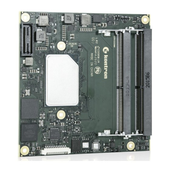
COMe-cEL6 - User Guide, Rev.1.3 1/ Introduction This user guide describes the COMe-cEL6 module made by Kontron and focuses on describing the modules special features. Kontron recommends users to study this user guide before powering on the module. 1.1. Product Description The COMe-cEL6 is small form factor COM Express®... -
Page 14: Product Naming Clarification
COMe-cEL6 - User Guide, Rev.1.3 Figure 2: COMe-cEL6 Bottom Side COMe Interface connector X1A 3-pin fan connector COMe Interface Connector X1B 1.2. Product Naming Clarification COM Express® defines a Computer-On-Module (COM), with all the components necessary for a bootable host computer, packaged as a super component. -
Page 15: Com Express® Documentation
COMe-cEL6 - User Guide, Rev.1.3 1.3. COM Express® Documentation The COM Express® specification defines the COM Express® module form factor, pinout and signals. For COM Express® specification information, visit the PCI Industrial Computer Manufacturers Group (PICMG®) website. 1.4. COM Express® Functionality All Kontron COM Express®... -
Page 16: 2/ Product Specification
COMe-cEL6 - User Guide, Rev.1.3 2/ Product Specification 2.1. Module Variants The COMe-cEL6 is available in different processor, memory and temperature variants to cover demands in performance, price and power. The following tables list the module variants for the commercial and industrial temperature grades. - Page 17 COMe-cEL6 - User Guide, Rev.1.3 Part Number Cooling Description 36034-0000-99-0 HSP COMe-cEL6 (E2) THREAD Heatspreader for COMe-cEL6 commercial and E2, threaded mounting holes 36034-0000-99-1 HSP COMe-cEL6 (E2) THROUGH Heatspreader for COMe-cEL6 commercial and E2, through holes 36099-0000-99-0 COMe Active Uni Cooler COM Express®...
-
Page 18: Functional Specification
COMe-cEL6 - User Guide, Rev.1.3 2.3. Functional Specification 2.3.1. Block Diagram Figure 3: Block Diagram COMe-cEL6 COM Express® connector CD – Pin-out Type 6 DP++ DP++ DDI2 DDI1 DDR4 3200 MT/s DDR4 3200 MT/s USBSS #0 (USB 3.0) SODIMM SODIMM Gen11 USBSS #1 iGFX... -
Page 19: Table 5: Processor Specification
COMe-cEL6 - User Guide, Rev.1.3 The following table lists the specification of the COMe-cEL6 processor variants. Table 5: Processor Specification Intel® Celeron® Pentium® Celeron® Pentium® J6413 J6426 N6211 N6415 # of Cores # of Threads Cache 1.5 MByte 1.5 MByte 1.5 MByte 1.5 MByte Base Frequency... -
Page 20: Platform Controller Hub (Pch)
COMe-cEL6 - User Guide, Rev.1.3 Intel® Atom™ Atom® Atom® Atom™ Atom™ Atom™ X6211E X6413E X6425E X6212RE X6414RE X6425RE Max. # PCIe Lanes Premium IO Intel® PSE Intel® PSE Intel® PSE Intel®PSE/TSN Intel®PSE/TSN Intel®PSE/TSN Intel® TCC Intel® TCC Intel® TCC Use Condition Embedded Embedded Embedded... -
Page 21: Graphics (Lvds Or Edp, Dp++)
COMe-cEL6 - User Guide, Rev.1.3 For volume production, if required, test and qualify other types of RAM. In order to qualify RAM it is recommend to configure three systems running a RAM Stress Test program in a heat chamber at 60°C, for a minimum of 24 hours. For a list of Kontron memory modules, see Table 4: Accessories. -
Page 22: Pci Express Lanes [0-5]
COMe-cEL6 - User Guide, Rev.1.3 2.3.7. PCI Express Lanes [0-5] The COMe-cEL6 supports up to six high-speed PCI Express 3.0 lanes PCIe [0-5], allowing for the connection of up to six separate external PCIe devices. The default PCIe configuration is (6 x1) with options for (1 x2 + 4 x1), (2 x2 + 2x1) and (1 x4 + 2x1). -
Page 23: Sata
COMe-cEL6 - User Guide, Rev.1.3 The following table lists the USB 2.0 port connections COMe Connector Description PCH USB Port USB0 USB2_0 USB 2.0 port USB1 USB2_1 USB 2.0 port USB2 USB2_2 USB 2.0 port USB3 USB2_3 USB 2.0 port USB4 USB2_4 USB 2.0 port... -
Page 24: Come High-Speed Serial Interfaces Overview
COMe-cEL6 - User Guide, Rev.1.3 Do not use an integrated RJ45 connector module with the center tap shorted together with all 4 pairs at the center-tap transformer. This increases the common mode noise and may create EMI. Kontron recommends adding a discrete common choke in series with each PHY MDI differential line pairs If this type of integrated connector module (ICM) is chosen. -
Page 25: Additional Features
COMe-cEL6 - User Guide, Rev.1.3 Operating System (OS) Board Support Packages for: Windows 10 Linux VxWorks Custom BIOS Settings/ Supported Flash Backup 2.3.14. Additional Features The following table lists General, Special and Optional COMe-cEL6 features. General Features On-module and external carrier boot from SPI LPC bus (default) pins shared with eSPI (eSPI overlay on request) LID Signal... -
Page 26: Electrical Specification
COMe-cEL6 - User Guide, Rev.1.3 2.4. Electrical Specification The module powers on by connecting to a carrier board via the COMe interface connector. Before connecting the module to the carrier board, ensure that the carrier board is switch off and disconnected from the main power supply at the time of connection. -
Page 27: Power Management
COMe-cEL6 - User Guide, Rev.1.3 2.4.1.1. Power Supply Voltage Rise Time The input voltage rise time is 0.1 ms to 20 ms from input voltage ≤10% to nominal input voltage. To comply with the ATX specification there must be a smooth and continuous ramp of each DC input voltage from 10 % to 90 % of the DC input voltage final set point. -
Page 28: Power Supply Modes
COMe-cEL6 - User Guide, Rev.1.3 COMe Signal Description Reset Button When the “SYS_RESET# “ pin is detected active (falling edge triggered), it allows the processor to perform a “graceful” reset, by waiting up to 25 ms for the SMBus (SYS_RESET#) to enter the idle state before forcing a reset, even though activity is still occurring. -
Page 29: Table 9: Single Power Supply Mode Settings
COMe-cEL6 - User Guide, Rev.1.3 2.4.3.2. Single Power Supply Mode To start the module in single power supply mode, connect VCC power and open PWR_OK at the high level. VCC can be 8.5 V to 20 V. To power on the module from S5 state, press the power button or reconnect VCC. Suspend/Standby states are not supported in single power supply mode. -
Page 30: Thermal Management
COMe-cEL6 - User Guide, Rev.1.3 2.5. Thermal Management 2.5.1. Heatspreader Plate Assembly and Metal Heat Slug A heatspreader plate (HSP) assembly is NOT a heat sink. The heatspreader plate works as a COM Express® standard thermal interface to be used in conjunction with a heat sink or external cooling devices. External cooling must be provided to maintain the heatspreader plate at proper operating temperatures. -
Page 31: Temperature Sensors
COMe-cEL6 - User Guide, Rev.1.3 2.5.5. Temperature Sensors The thermal resistor (Figure 4, pos. 1) measures the Multi Chip Package (MCP) temperature. The thermal resistor is not capable of measuring very fast rises and falls in temperature and measurements may show a certain non- linearity. -
Page 32: On-Board Fan Connector
COMe-cEL6 - User Guide, Rev.1.3 2.5.6. On-board Fan Connector The fan connector powers, controls and monitors an external fan. To connect a standard 3-pin connector fan to the module, use Kontron’s fan cable, see Table 4: Accessories. Figure 5: Fan Connector 3-Pin 3-pin fan connector Table 11: Fan Connector (3-Pin) Pin Assignment Signal... -
Page 33: Standards And Certifications
COMe-cEL6 - User Guide, Rev.1.3 2.7. Standards and Certifications The COMe-cEL6 complies with the following standards and certificates. If modified, the prerequisites for specific approvals may no longer apply. For more information, contact Kontron Support. Table 13: Standards and Certifications Emission EN 55032 Class B Electromagnetic compatibility of multimedia equipment -... -
Page 34: Figure 6: Mtbf De-Rating Values
COMe-cEL6 - User Guide, Rev.1.3 The MTBF estimated value above assumes no fan, but a passive heat sinking arrangement. Estimated RTC battery life (as opposed to battery failures) is not accounted for and needs to be considered separately. Battery life depends on both temperature and operating conditions. -
Page 35: Mechanical Specification
COMe-cEL6 - User Guide, Rev.1.3 2.8. Mechanical Specification The COMe-cEL6 is compliant with the COM Express® PICMG COM.0 Rev 3.0 mechanical specification. 2.8.1. Module Dimensions The compact module dimensions are: 95 mm x 95 mm (3.74” x 3.74“). Figure 7: Module Dimensions Top Side *All dimensions are in mm. -
Page 36: Module Height
COMe-cEL6 - User Guide, Rev.1.3 Figure 8: Module Dimensions Bottom Side *All dimensions are in mm. 2.8.2. Module Height The COM Express® specification defines a module height of approximately 13 mm, when measured from the bottom of the module’s PCB board, to the top of the heatspreader. The overall height of the module and carrier board depends on the implemented cooling solution. -
Page 37: Metal Heat Slug Dimensions
COMe-cEL6 - User Guide, Rev.1.3 2.8.3. Metal Heat Slug Dimensions The metal heat slug (35 mm x 24 mm) is located on top of the multi-chip package. Figure 10: Metal Heat Slug Dimensions *All dimensions shown in mm. Metal heat slug www.kontron.com // 37... -
Page 38: 3/ Features And Interfaces
COMe-cEL6 - User Guide, Rev.1.3 3/ Features and Interfaces 3.1. ACPI Power States ACPI enables the system to power down and save power (suspend) when not required and wake up when required (resume). The ACPI controls the power states S0-S5, where S0 has the highest priority and S5 the lowest priority. The COMe-cEL6 supports ACPI 6.0 and the power states S0, S3, S4, S5 only. -
Page 39: Fast I2C
COMe-cEL6 - User Guide, Rev.1.3 3.4. Fast I2C The fast I2C bus transfers data between components data transfers at up to 400 kHz clock speed. The I2C controller supports: Multimaster transfers Clock stretching Collision detection Interruption on completion of an operation To change the I2C bus speed, in the BIOS setup menu select: Advanced>Miscellaneous>I2C Speed>... -
Page 40: Lpc
COMe-cEL6 - User Guide, Rev.1.3 3.7. LPC The Low Pin Count (LPC) interface is pin shared with eSPI. The LPC interface is the default connection to the COMe connector. The module’s signal ESPI_EN# (pinB47) indicates whether ESPI-mode or LPC-mode is enabled/disabled. In LPC mode “ESPI_EN#”... -
Page 41: Sdio (Option)
COMe-cEL6 - User Guide, Rev.1.3 3.11. SDIO (option) The SDIO feature is supported using the processor. To find out more about SDIO, contact Kontron Support. 3.12. Serial Peripheral Interface (SPI) The Serial Peripheral Interface (SPI) bus is a synchronous serial data link where devices communicate in master/slave mode, where the master device initiates the data frame. -
Page 42: Booting The Spi Flash Chip
COMe-cEL6 - User Guide, Rev.1.3 3.12.2. Booting the SPI Flash Chip Initially, the EFI Shell is booted with an USB key containing the binary used to flash the on-module SPI Flash chip. program the external SPI Flash chip on the carrier board with the BIOS binary, use an external programmer. Register for Kontron’s Customer Section to get access to BIOS downloads and PCN service. -
Page 43: Uart (Option)
COMe-cEL6 - User Guide, Rev.1.3 3.14. UART (option) The UART option supports the serial communications interface up to two serial RX/TX ports defined in the COMe specification on pins A98 (SERO_TX) and A99 (SERO_RX) for UART0, and pins A101 (SER1_TX) and A102 (SER1_RX) for UART1. -
Page 44: 4/ System Resources
COMe-cEL6 - User Guide, Rev.1.3 4/ System Resources 4.1. I2C Bus The following table specifies the devices connected to the accessible I2C bus including the I2C address. The I2C bus is available at COMe pin A83, I2C_CK and pin A84, I2C_DAT. Table 19: I2C Bus Port Address 8-bit 7-bit... -
Page 45: 5/ Come Interface Connector
COMe-cEL6 - User Guide, Rev.1.3 5/ COMe Interface Connector The two 220-pin COMe interface connectors X1A and X1B, each with two rows called row A & B on primary connector X1A and row C & D on secondary connector X1B, are mounted on the bottom side of the module. Figure 11: COMe Interface Connector COMe interface connector (X1A) PinA1... -
Page 46: X1A And X1B Signals
COMe-cEL6 - User Guide, Rev.1.3 5.2. X1A and X1B Signals The terms used in the connector pin assignment tables and a description of the signal type can be found in Table 21: General Signal Description. If additional information is required refer to, the Appendix at the end of this user guide and the PICMG specification COM.0 Rev 3.0 Type 10 standard. -
Page 47: Come Interface Connectors (X1A, X1B) Pin Assignment
COMe-cEL6 - User Guide, Rev.1.3 5.3. COMe Interface Connectors (X1A, X1B) Pin Assignment The following tables list the pin assignment of the two 220-pin COMe interface connectors X1A (Row A1 to A110) and (Row B1 to B110) and X1B (Row C1 to C110) and (Row D1 to D110). 5.3.1. - Page 48 COMe-cEL6 - User Guide, Rev.1.3 COMe Signal Description Type Termination Description USB_6_7_OC# USB overcurrent indicator port 6/7 I-3.3 PU 10 kΩ, 3.3 V (S5) USB4- USB 2.0 data differential pair port 4 DP-I/O Integrated PD 14.25 KΩ to USB4+ 24.8 kΩ in PCH Power Ground PWR GND USB2-...
- Page 49 COMe-cEL6 - User Guide, Rev.1.3 COMe Signal Description Type Termination Description LVDS_A3+ LVDS channel A DAT3 DP-O LVDS_A3- Power Ground PWR GND LVDS_A_CK+ LVDS channel A clock or EDP lane 3 transmit DP-O Clock 20 MHz to 80 MHz LVDS_A_CK- LVDS_I2C_CK LVDS I2C Clock for (DDC) / I/O-3.3...
-
Page 50: Connector X1A Row B1 - B110
COMe-cEL6 - User Guide, Rev.1.3 5.3.2. Connector X1A Row B1 – B110 Table 23: Connector X1A Row B1 to B110 Pin Assignment COMe Signal Description Type Termination Description Power Ground PWR GND GBE0_ACT# Ethernet Controller activity LED indicator LPC_FRAME# / LPC Frame indicator / O-3.3 / ESPI_CSO... - Page 51 COMe-cEL6 - User Guide, Rev.1.3 COMe Signal Description Type Termination Description Power Ground PWR GND SPKR Speaker output provides the PC beep O-3.3 signal and is mainly intended for debugging purposes I2C_CK I2C port clock output O-3.3 PU 2.21 kΩ 3.3V (S5) I2C_DAT I2C port data I/O line...
- Page 52 COMe-cEL6 - User Guide, Rev.1.3 COMe Signal Description Type Termination Description LVDS_B2+ LVDS Channel B Dat2+/- DP-O LVDS_B2- LVDS_B3+ LVDS Channel B Dat3+/- DP-O LVDS_B3- LVDS/BKLT_EN LVDS /EDP panel backlight enable 0-3.3 PD 100 kΩ (ON) Power Ground PWR GND LVDS_B_CK+ LVDS Channel B Clock+/- DP-O...
-
Page 53: Connector X1B Row C1 - C110
COMe-cEL6 - User Guide, Rev.1.3 5.3.3. Connector X1B Row C1 – C110 Table 24: Connectors X1B Row C1 to C110 COMe Signal Description Type Termination Comment Power ground PWR GND USB_SSRX0- USB SuperSpeed receive data pair 0 DP-I To USB hub USB_SSRX0+ Power ground PWR GND... - Page 54 COMe-cEL6 - User Guide, Rev.1.3 COMe Signal Description Type Termination Comment DDI3_PAIR1+ Digital Display Interface pair 3 DDI3_PAIR1- DDI3_HPD RSVD Reserved for future use DDI3_PAIR2+ Digital Display Interface pair 2 DDI3_PAIR2- RSVD Reserved for future use DDI3_PAIR3+ Digital Display Interface pair 3 DDI3_PAIR3- Power Ground PWR GND...
- Page 55 COMe-cEL6 - User Guide, Rev.1.3 COMe Signal Description Type Termination Comment PEG_RX12+ PCI Express Graphics Receive Inputs differential Pair 12 PEG_RX12- Power ground PWR GND PEG_RX13+ PCI Express Graphics Receive Inputs differential Pair 13 PEG_RX13- Power ground PWR GND RSVD Reserved for future use PEG_RX14+ PCI Express Graphics Receive Inputs...
-
Page 56: Connector X1B Row D1 - D110
COMe-cEL6 - User Guide, Rev.1.3 5.3.4. Connector X1B Row D1 – D110 Table 25: Connector X1A Row D1 – D110 COMe Signal Description Type Termination Comment Power ground PWR GND USB_SSTX0- USB SuperSpeed transmit data path 0 DP-O USB_SSTX0+ Power ground PWR GND USB_SSTX1- USB SuperSpeed transmit data path 1... - Page 57 COMe-cEL6 - User Guide, Rev.1.3 COMe Signal Description Type Termination Comment DDI2_HPD DDI2 Hotplug Detect: Multiplexed with I-3.3 PD 100 KΩ DP2_HPD and HDMI2_HPD RSVD Reserved for future use DDI2_PAIR2+ Multiplexed with DP2_LANE2+/- and DP-O TMDS2_DATA0+/- DDI2_PAIR2- RSVD Reserved for future use DDI2_PAIR3+ Multiplexed with DP2_LANE3+/- and DP-0...
- Page 58 COMe-cEL6 - User Guide, Rev.1.3 COMe Signal Description Type Termination Comment PEG_TX12+ PCI Express Graphics Transmit Output differential Pair 12 PEG_TX12- Power ground PWR GND PEG_TX13+ PCI Express Graphics Transmit Output differential Pair 13 PEG_TX13- Power ground PWR GND RSVD Reserved for future use PEG_TX14+ PCI Express Graphics Transmit Output...
-
Page 59: 6/ Uefi Bios
COMe-cEL6 - User Guide, Rev.1.3 6/ UEFI BIOS 6.1. Starting the uEFI BIOS The COMe-cEL6 uses a Kontron-customized, pre-installed and configured version of AMI Aptio V BIOS ® based on the Unified Extensible Firmware Interface (uEFI) specification and the Intel® Platform Innovation Framework for EFI. The uEFI BIOS provides a variety of new and enhanced functions specifically tailored to the hardware features of the COMe-cEL6. -
Page 60: Getting Help
COMe-cEL6 - User Guide, Rev.1.3 The currently active menu and the currently active uEFI BIOS Setup item are highlighted in white. Use the left and right arrow keys to select the Setup menu. Each Setup menu provides two main frames. The left frame displays all available functions and configurable functions are displayed in blue. -
Page 61: Main Setup Menu
COMe-cEL6 - User Guide, Rev.1.3 6.4.1. Main Setup Menu The Main setup menu lists sub-screens and second level sub-screens of the functions supported within the Main setup menu. Figure 13: Main Setup Menu Screen The following table shows the Main Menu sub-screens and describes the function. Default settings are in bold. Table 27: Main Setup Menu Sub-screen Description... -
Page 62: Advanced Setup Menu
COMe-cEL6 - User Guide, Rev.1.3 6.4.2. Advanced Setup Menu The Advanced Setup menu lists sub-screens and second level sub-screens of the functions supported within the Advanced setup menu. Setting items, on this screen, to incorrect values may cause system malfunctions. Figure 14: Advanced Setup Menu Screen The following table shows the Advanced sub-screen and describes the function. - Page 63 COMe-cEL6 - User Guide, Rev.1.3 Sub-screen Next Level Sub-screens / Description RC ACPI Wake System System wake on alarm event. When enabled system will wake on the Settings> from S5 via RTC> hr:min::sec::specified (continued) [Enabled, Disabled] Low Power S0 Determines If ACPI Lower power S0 idle capability (mutually exclusive Idle Capability>...
- Page 64 COMe-cEL6 - User Guide, Rev.1.3 Sub-screen Next Level Sub-screens / Description Power and CPU Power Read only field Perfomance> Management> P1 to P3 Fused Max Core Ratio Boot Select the performance state that the BIOS will set Performance starting from rest vector. Mode>...
- Page 65 COMe-cEL6 - User Guide, Rev.1.3 Sub-screen Next Level Sub-screens / Description CPU Power View/Configure Power and 2-Core Ratio Range 0 to 83. Minimum range Perfomance> Management> Turbo Options> Limit Override> varies between processors. This (continued) (continued) (continued) 2-Core ration limit must be less than or equal to 1-Core ratio limit.
- Page 66 COMe-cEL6 - User Guide, Rev.1.3 Sub-screen Next Level Sub-screens / Description CPU Power Power and IO MWait Enable: mapa IO read instructions sent to IO Perfomance> Management> Redirection> registers PMG_IO_BASE_ADDRBASE+off set to (continued) (continued) MWait (offset) [Enabled, Disabled] Package Maximum c-state limit setting. C-State Limit>...
- Page 67 COMe-cEL6 - User Guide, Rev.1.3 Sub-screen Next Level Sub-screens / Description Power and CPU Power Custom P- Sets the number of customer P-states. At least 2 Performance> Management> State Table> states must be present. [0] (continued) (continued) Power Limit 3 Read only field Settings>...
- Page 68 COMe-cEL6 - User Guide, Rev.1.3 Sub-screen Next Level Sub-screens / Description PCH-FW Firmware Update Anti-Rollback Set HW- Hardware enforced anti-rollback Configuration> Configuration> enforced for current ARB-SVN value. Configuration> (continued) (continued) Anti-Rollback Firmware with lower ARB-SVN is (continued) for Current blocked from execution. Value SVN>...
- Page 69 COMe-cEL6 - User Guide, Rev.1.3 Sub-screen Next Level Sub-screens / Description Thermal Platform Critical Trip Controls temperature of ACPI Critical Trip Point, at Consideration> Thermal Point> which OS shuts down the system. Note: 119 C is the (continued) Configuration> PLAN of Record (POR) for all Intel mobile processors.
- Page 70 COMe-cEL6 - User Guide, Rev.1.3 Sub-screen Next Level Sub-screens / Description ACPI D3Cold USB Port 2> USB RTD3 support for super speed USB 3.1 and high speed USB 2.0 Settings> devices [Enabled, Disabled] (continued) ZPODD> Zero power ODD (ZPODD) only for boar with SPODD support [Enabled, Disabled] WWAN>...
- Page 71 COMe-cEL6 - User Guide, Rev.1.3 Sub-screen Next Level Sub-screens / Description Trusted Pending Schedule an operating for security device. Note: computer reboots Computing> Operation> during restart to change the state of security device. (continued) [None, Clear] Platform [Enabled, Disabled] Hierarchy> Storage [Enabled, Disabled] Hierarchy>...
- Page 72 COMe-cEL6 - User Guide, Rev.1.3 Sub-screen Next Level Sub-screens / Description Miscellaneous> Lid Switch Mode> Shows or hides LID switch in ACPI OS. (continued) [Enabled, Disabled] Sleep Button Shows or hides sleep button in ACPI OS Mode> [Enabled, Disabled] ACPI Temperature Sets mode for temperature polling through OSPM Polling>...
- Page 73 COMe-cEL6 - User Guide, Rev.1.3 Sub-screen Next Level Sub-screens / Description Hardware External Fan> Monitor> Fan Control> Sets fan control mode where disable totally stops the fan.[Disabled, (continued) Manual, Auto] Fan Pulse> No. Pulses the fan produces during one revolution (range 1 to 4) Fan Trip Point Temperature at which the fan accelerates (range 20 to 80 C) Speed>...
- Page 74 COMe-cEL6 - User Guide, Rev.1.3 Sub-screen Next Level Sub-screens / Description Active Serial Logical Device Read only field Configuration> port> Settings IO=2F8h; IRQ=3; (continued) (continued) Current> Possible: Use Allows the user to change the device’s resource Automatic settings. New settings are reflected on the setup Settings>...
- Page 75 COMe-cEL6 - User Guide, Rev.1.3 Sub-screen Next Level Sub-screens / Description XHCI Hand-off> This is a work around for OSs without XHCI hand-off support. The Configuration> XHCI ownership change should be claimed by XHCI driver (continued) [Enabled, Disabled] USB Mass Storage [Enabled, Disabled] Driver Support>...
- Page 76 COMe-cEL6 - User Guide, Rev.1.3 Sub-screen Next Level Sub-screens / Description User Password Admin Password Read only field Management> Management> [Not Installed] Change Admin New password must be between 8 and 32 Characters include lower Password> and upper case, number and symbol. Note: input old admin password I fit was set, then you can change the password to a new one.
-
Page 77: Chipset Setup Menu
COMe-cEL6 - User Guide, Rev.1.3 6.4.3. Chipset Setup Menu The Chipset Setup menu lists sub-screens and second level sub-screens of the functions supported within the Chipset setup menu. Figure 15: Chipset Setup Menu The following table shows sub-screens and describes the function. Default settings are in bold. Table 29: Chipset Setup Menu Sub-screens and Functions Sub-screen Next Level Sub-screens / Description... - Page 78 COMe-cEL6 - User Guide, Rev.1.3 Sub-screen Next Level Sub-screens / Description System Agent Memory Memory Memory Power Refresh_ [Disables, 1- Enabled for Configuration> Thermal and Thermal (SA) Warm or Hot, 2- Configuration> Throttling> (continued) Mode> Configuration> Enabled Hot only] (continued) (continued) (continued) DDR4...
- Page 79 COMe-cEL6 - User Guide, Rev.1.3 Sub-screen Next Level Sub-screens / Description System Agent Memory Train On Warm [Enabled, Disabled] Configuration> (SA) Boot> Configuration> (continued) BDAT Memory Read Only field (continued) Test Type> [Rank margin Tool Rank] Graphics Skip Scanning of Enabled- will not scan for external Gfx card on PEG and Configuration>...
- Page 80 COMe-cEL6 - User Guide, Rev.1.3 Sub-screen Next Level Sub-screens / Description System Agent CPU Crash Log [Enabled, Disabled] (SA) (Device 10)> Configuration> CRID Support> SA CRID and TCSS CRID control for Intel SIPP (continued) [Enabled, Disabled] Above 4 GB Enables automatically when aperture size is set to 2048 MB. MMIO BIOS [Enabled, Disabled] Assignment>...
- Page 81 COMe-cEL6 - User Guide, Rev.1.3 Sub-screen Next Level Sub-screens / Description PCH-IO PCI Express PCIE Express PTM> Precision Time Measurement Configuration> Root Port Configuration> Enabled, Disabled] [1 to 4]> (continued) (continued) DPC> Downstream Port Containment (continued) [Enabled, Disabled] EDPC> Extensions for Downstream Port Containment [Enabled, Disabled] URR>...
- Page 82 COMe-cEL6 - User Guide, Rev.1.3 Sub-screen Next Level Sub-screens / Description PCH-IO PCI Express PCIE Express PCH PCIe LTR Configuration Configuration> Root Port Configuration> LTR> PCIe latency reporting [1 to 4]> (continued) (continued) [Enabled, Disabled] (continued) Snoop Latency Disabled- disable override Override>...
- Page 83 COMe-cEL6 - User Guide, Rev.1.3 Sub-screen Next Level Sub-screens / Description SATA Controllers> PCH-IO SATA [Enabled, Disabled] Configuration> Configuration> SATA Port Multiplier> Determines how the SATA controllers(s) operate (continued) [AHCI] SATA Mode Selection> [Enabled, Disabled] SATA Test Mode> [Enabled, Disabled] Software Feature HDD Unlock>...
- Page 84 COMe-cEL6 - User Guide, Rev.1.3 Sub-screen Next Level Sub-screens / Description PCH-IO SATA SATA Port 0 Disable is default- check module design before Configuration> Configuration> RXPolarity> enabling. (continued) (continued) [Enabled, Disabled] DITO Configuration> [Enabled, Disabled] DITO Value> Read Only port [625] DM value>...
- Page 85 COMe-cEL6 - User Guide, Rev.1.3 Sub-screen Next Level Sub-screens / Description PCH-IO HD Audio HD Audio> Enabled: HDA unconditionally enabled Configuration> Configuration> (continued) [Enabled, Disabled] (continued) (continued) Audio DSP> Enables or disables the Audio DSP. [Enabled, Disabled] HD Audio Advanced iDisplay Audio Disconnects the SDI2 Configuration>...
- Page 86 COMe-cEL6 - User Guide, Rev.1.3 Sub-screen Next Level Sub-screens / Description PCH/IO Serial IO UART2 Controller Set UART2 mode Configuration> Configuration> (COMe UART1> -DBG used for BIOS log print and/or Kernel OS (continued) (continued) UART2 Controller debug (COMe UART1> -COM-16550 Compatibility serial power with power (continued) gating support [Disabled, enabled, Communication port (COM)]...
- Page 87 COMe-cEL6 - User Guide, Rev.1.3 Sub-screen Next Level Sub-screens / Description PCH/IO TSN GBE PSE TSN GBE 0 Link PSE TSN GBE 0 link speed configuration. Configuration> Configuration> Speed> [RefClk 38.4MHz 2.5Gbps, RefClk 38.4MHz 1Gbps] (continued) (continued) Flex IO Lane Read only field Assignment>...
- Page 88 COMe-cEL6 - User Guide, Rev.1.3 Sub-screen Next Level Sub-screens / Description PCH/IO Extended BIOS Enable: redirects memory cycles falling in a specific area to SPI flash Configuration> Range Decode> controller. (continued) [Enabled, Disabled] Sub-Screen Next level Sub-screens / Description Data Format> Read only field Configuration>...
-
Page 89: Security Setup Menu
COMe-cEL6 - User Guide, Rev.1.3 6.4.4. Security Setup Menu The security Setup menu lists sub-screens and second level sub-screens of the functions supported within the Security setup menu. Figure 16: Security Setup Menu The following table shows the Security sub-screens and functions and describes the content. Table 30: Security Setup Menu Sub-screens and Functions Sub-screen Next Level Sub-screens / Description... - Page 90 COMe-cEL6 - User Guide, Rev.1.3 Sub-screen Next Level Sub-screens / Description PO: CT120BX500SSD1> Set User Set HDD user password. (continued) Password> Advisable to power cycle system after setting Hard Disk Passwords. Discard or save changes option in setup does not have any impact on HDD when password is set or removed.
-
Page 91: Boot Setup Menu
COMe-cEL6 - User Guide, Rev.1.3 6.4.5. Boot Setup Menu The Boot Setup menu lists sub-screens of the functions supported within the Boot setup menu. Figure 17: Boot Setup Menu Screen The following table shows the Boot Setup sub-screens and functions and describes the content. Default settings are in bold. -
Page 92: Save And Exit Setup Menu
COMe-cEL6 - User Guide, Rev.1.3 6.4.6. Save and Exit Setup Menu The Save and Exit Setup menu lists sub-screens of the functions supported within the Save and Exit setup menu. Figure 18: Save and Exit Setup Menu Screen The following table shows the Save and Exit sub-screens and functions and describes the content. Table 32: Save and Exit Setup Menu Sub-screens and Functions Sub-screen Description... -
Page 93: The Uefi Shell
COMe-cEL6 - User Guide, Rev.1.3 6.5. The uEFI Shell The Kontron uEFI BIOS features a built-in and enhanced version of the uEFI Shell. For a detailed description of the available standard shell scripting, refer to the EFI Shell User Guide. For a detailed description of the available standard shell commands, refer to the EFI Shell Command Manual. -
Page 94: Uefi Shell Scripting
COMe-cEL6 - User Guide, Rev.1.3 6.6. uEFI Shell Scripting 6.6.1. Startup Scripting If the <ESC> key is not pressed and the timeout has run out then the uEFI Shell automatically tries to execute some startup scripts. The UEFI shell searches for scripts and executes them in the following order: Initially searches for Kontron flash-stored startup script. -
Page 95: Firmware Update
COMe-cEL6 - User Guide, Rev.1.3 6.7. Firmware Update Firmware updates are typically delivered as a ZIP archive. Please find the latest available BIOS-ZIP archive on Kontron's Customer Section. Further information about the firmware update procedure can be found in the included "flash_instruction.txt"-file. -
Page 96: 7/ Technical Support
COMe-cEL6 - User Guide, Rev.1.3 7/ Technical Support For technical support contact our Support Department: E-mail: support@kontron.com Phone: +49-821-4086-888 Make sure you have the following information available when you call: Product ID Number (PN) Serial Number (SN) ... -
Page 97: 8/ Warranty
COMe-cEL6 - User Guide, Rev.1.3 8/ Warranty Kontron defines product warranty in accordance with regional warranty definitions. Claims are at Kontron’s discretion and limited to the defect being of a material nature. To find out more about the warranty conditions and the defined warranty period for your region, follow the steps below: Visit Kontron’s Term and Conditions webpage. -
Page 98: List Of Acronyms
COMe-cEL6 - User Guide, Rev.1.3 List of Acronyms Table 33: List of Acronyms ACPI Advanced Configuration and Power Keyboard Video Mouse Interface Low Pin Count (Bus) Application Programming Interface LVDS Low Voltage Differential Signaling Base Management Controller Media Access Control (Ethernet layer) Command-Line Interface Multi Chip Package Computer-on-Module... -
Page 99: About Kontron
COMe-cEL6 – User Guide, Rev.1.3 About Kontron Kontron is a global leader in IoT/Embedded Computing Technology (ECT). As a part of technology group S&T, Kontron, together with its sister company S&T Technologies, offers a combined portfolio of secure hardware, middleware and services for Internet of Things (IoT) and Industry 4.0 applications. With its standard products and tailor-made solutions based on highly reliable state-of-the-art embedded technologies, Kontron provides secure and innovative applications for a variety of industries.
Need help?
Do you have a question about the kontron COMe-cEL6 and is the answer not in the manual?
Questions and answers