
Related Manuals for S&T Kontron COMe-cTL6


Summary of Contents for S&T Kontron COMe-cTL6
- Page 1 USER GUIDE COMe-cTL6 User Guide Rev. 1.7 Doc. ID: 1068-0490 www.kontron.com // 1...
- Page 2 COMe-cTL6 – User Guide Rev. 1.7 This page has been intentionally left blank www.kontron.com // 2...
- Page 3 COMe-cTL6 – User Guide Rev. 1.7 COME-CTL6 – USER GUIDE Disclaimer Kontron would like to point out that the information contained in this user guide may be subject to alteration, particularly as a result of the constant upgrading of Kontron products. This document does not entail any guarantee on the part of Kontron with respect to technical processes described in the user guide or any product characteristics set out in the user guide.
- Page 4 COMe-cTL6 – User Guide Rev. 1.7 Intended Use THIS DEVICE AND ASSOCIATED SOFTWARE ARE NOT DESIGNED, MANUFACTURED OR INTENDED FOR USE OR RESALE FOR THE OPERATION OF NUCLEAR FACILITIES, THE NAVIGATION, CONTROL OR COMMUNICATION SYSTEMS FOR AIRCRAFT OR OTHER TRANSPORTATION, AIR TRAFFIC CONTROL, LIFE SUPPORT OR LIFE SUSTAINING APPLICATIONS, WEAPONS SYSTEMS, OR ANY OTHER APPLICATION IN A HAZARDOUS ENVIRONMENT, OR REQUIRING FAIL-SAFE PERFORMANCE, OR IN WHICH THE FAILURE OF PRODUCTS COULD LEAD DIRECTLY TO DEATH, PERSONAL INJURY, OR SEVERE PHYSICAL OR...
- Page 5 COMe-cTL6 – User Guide Rev. 1.7 Revision History Revision Brief Description of Changes Date of Issue Author Initial version 2021-Sept-17 RTC range updated 2022-Jan-04 UART0 notice moved to 6.4.3 2022-Jan-31 BIOS Update 2022-Mar-18 TDP parameter in Table 9 modified 2022-Apr-27 New coolers in Table 6: General Accessories 2022-May-19 I2C pin numbering changed Ch 4.1...
-
Page 6: Symbols
COMe-cTL6 – User Guide Rev. 1.7 Symbols The following symbols may be used in this user guide DANGER indicates a hazardous situation which, if not avoided, will result in death or serious injury. WARNING indicates a hazardous situation which, if not avoided, could result in death or serious injury. -
Page 7: For Your Safety
COMe-cTL6 – User Guide Rev. 1.7 For Your Safety Your new Kontron product was developed and tested carefully to provide all features necessary to ensure its compliance with electrical safety requirements. It was also designed for a long fault-free life. However, the life expectancy of your product can be drastically reduced by improper treatment during unpacking and installation. -
Page 8: Lithium Battery Precautions
COMe-cTL6 – User Guide Rev. 1.7 Lithium Battery Precautions If your product is equipped with a lithium battery, take the following precautions when replacing the battery. Danger of explosion if the battery is replaced incorrectly. Replace only with same or equivalent battery type recommended by the manufacturer. ... -
Page 9: Table Of Contents
COMe-cTL6 – User Guide Rev. 1.7 Table of Contents Symbols ..........................................6 For Your Safety ........................................7 High Voltage Safety Instructions .................................. 7 Special Handling and Unpacking Instruction ............................7 Lithium Battery Precautions ..................................8 General Instructions on Usage..................................8 Quality and Environmental Management .............................. - Page 10 COMe-cTL6 – User Guide Rev. 1.7 2.3.23. Carrier Board Reset (CB_RESET#) ............................... 33 2.3.24. System Reset (SYS_RESET#) ................................ 33 2.3.25. Power Button (PWRBTN#) ................................33 2.3.26. Batlow ........................................33 2.3.27. LID Switch (LID#) ....................................33 2.3.28. Sleep Button (SLEEP#) ..................................33 2.3.29.
-
Page 11: List Of Tables
COMe-cTL6 – User Guide Rev. 1.7 4.1. I2C Bus ......................................... 53 4.2. System Management (SM) Bus ................................53 COMe Interface Connectors (X1A and X1B) ..........................54 5.1. Connecting COMe Interface Connector to Carrier Board ......................54 5.2. X1A and X1B Signals ....................................55 5.3. - Page 12 COMe-cTL6 – User Guide Rev. 1.7 Table 18: General Purpose PCI Express 3.0 ............................. 28 Table 19: PCI Express Graphics 4.0 (PEG) ..............................28 Table 20: PCI Express Reference Clock ..............................28 Table 21: USB ........................................29 Table 22: USB Overcurrent ................................... 29 Table 23: SATA ........................................
-
Page 13: List Of Figures
COMe-cTL6 – User Guide Rev. 1.7 Table 74: List of Acronyms ..................................104 List of Figures Figure 1: COMe-cTL6 ......................................14 Figure 2: Block Diagram COMe-cTL6................................21 Figure 3: Front View COMe-cTL6 ................................22 Figure 4: Rear View COMe-cTL6 ................................. 23 Figure 5: Block Diagram 11th Generation processor (Source: Intel) .................... -
Page 14: 1/ Introduction
The Kontron COMe-cTL6 (E2) modules allow up to 48 GB of DDR4 memory. The board is also suited for harsh operating conditions in industrial environments. For example, rugged modules are available that can be used within a temperature range from -40°C to +85°C. -
Page 15: Product Naming Clarification
COMe-cTL6 – User Guide Rev. 1.7 1.2. Product Naming Clarification COM Express® defines a Computer-On-Module, or COM, with all the components necessary for a bootable host computer, packaged as a super component. The product names for Kontron COM Express® Computer-on-Modules consist of: ... -
Page 16: Com Express® Benefits
COMe-cTL6 – User Guide Rev. 1.7 Type 6 Pinout COMe-cTL6 Pinout Feature Gen1 by default as support depends on appropriate carrier board design 1x (optional) LVDS Dual Channel Dual Channel LVDS with option to overlay with embedded Display port (eDP) DP++ (eDP/DP/HDMI/DVI/VGA) External SMB... -
Page 17: 2/ Product Specification
COMe-cTL6 – User Guide Rev. 1.7 2/ Product Specification 2.1. Module Variants The COMe-cTL6 is available in different processor and temperature variants to cover demands in performance, price and power. 2.1.1. Commercial Grade Modules (0°C to +60°C) Commercial Grade Modules (0°C to +60°C) are available as a standard product number. Table 2: Commercial Grade Modules (0°C to +60°C) Product Number Product Name... -
Page 18: E2 Modules (E2, -40°C To +85°C)
COMe-cTL6 – User Guide Rev. 1.7 2.1.3. E2 Modules (E2, -40°C to +85°C) The following table provides a list of E2 modules available for E2 temperature grade (-40°C to +85°C) by design. Table 3: E2 Modules (E2, -40°C to +85°C operating) Product Number Product Name Description... -
Page 19: Table 6: General Accessories
COMe-cTL6 – User Guide Rev. 1.7 Table 6: General Accessories Part Number Cooling Solutions Comments 36099-0000-99-4 COMe Active Uni Cooler2 (w/o COM Express® Universal Active Cooler for HSP) Heatspreader Mounting (95x95x14.3) - 90° turnable 36099-0000-99-5 COMe Passive Uni Cooler2 (w/o COM Express®... -
Page 20: Functional Specification
COMe-cTL6 – User Guide Rev. 1.7 2.3. Functional Specification 2.3.1. Technical Data Table 8: Technical Data Function Definition Compliance COM Express® compact, Pin-out Type 6 Dimensions (H X W) 95mm x 95 mm CPUs Intel 11th generation processors: i7-1185G7E i5-1145G7E i3-1115G4E 6305E i7-1185GRE... -
Page 21: Block Diagram
COMe-cTL6 – User Guide Rev. 1.7 2.3.2. Block Diagram The following figure displays the system block diagram applicable to all COMe-cTL6 modules. Figure 2: Block Diagram COMe-cTL6 www.kontron.com // 21... -
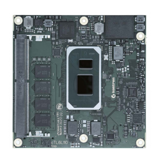
Page 22: Front View
COMe-cTL6 – User Guide Rev. 1.7 2.3.3. Front View Figure 3: Front View COMe-cTL6 SoC Processor DDR4 memory down 1xS0-DIMM DDR4 slot Embedded Controller NVME Mass Storage Ethernet MAC/PHY Intel I255 eDP-to-LVDS bridge Temp. Sensor #1 CPU www.kontron.com // 22... -
Page 23: Rear View
COMe-cTL6 – User Guide Rev. 1.7 2.3.4. Rear View Figure 4: Rear View COMe-cTL6 1. DDR4 memory down 2. 2x COMe Connectors 3. Fan Connector 4. XDP Connector (optional) 5. Programming Connector for embedded Controller 6. SPI-Flash 7. Second SPI-Flash (optional) 8. -
Page 24: Processors
COMe-cTL6 – User Guide Rev. 1.7 2.3.5. Processors 11th Gen Intel® Core™ processors come in two classes – embedded and industrial – to provide a foundation for durable, long-life equipment. Temperature ranges of the industrial SoC are from -40°C to 100°C and Embedded SoCs have a temperature range from 0°... -
Page 25: System Memory
COMe-cTL6 – User Guide Rev. 1.7 Table 9: 11th Generation Intel® Processor Specifications Processor i7-1185G7E i5-1145G7E i3-1115G4E 6305E i7-1185GRE i5-1145GRE i3-1115GRE Classification Embedded (0°C to 100°C) Industrial (-40°C to 100°C) # of Cores/ Threads Processor 1.8/4.4 1.5/4.1 GHz 2.2/3.9 1.8/- GHz 1.8/4.4 1.5/4.1 GHz 2.2/3.9... -
Page 26: Graphics
COMe-cTL6 – User Guide Rev. 1.7 In general, memory modules have a much lower longevity than embedded motherboards, and therefore the EOL of the memory modules may occur several times during the lifetime of the module. Kontron guarantees to maintain memory modules by replacing EOL memory module with another qualified similar module. -
Page 27: Table 14: Ddi2 Interfaces
COMe-cTL6 – User Guide Rev. 1.7 COMe Connector Description DDI1_DDC_AUX_SEL Connected to DP++-AUX Conversion DDI1_HPD DDSP_HPD1 Table 14: DDI2 Interfaces COMe Connector Description DDI2_PAIR[0:3] TCP1_TX[0:3] DDI2_CTRLCLK_AUX+ TCP1_AUX_P/DDP2_CTRLCLK DDI2_CTRLDATA_AUX- TCP1_AUX_N/DDP2_CTRLDATA DDI2_DDC_AUX_SEL Connected to DP++ AUX Conversion DDI2_HPD DDSP_HPD2 Table 15: DDI3 Interfaces COMe Connector Description DDI3_PAIR[0:3]... -
Page 28: Hd Audio
COMe-cTL6 – User Guide Rev. 1.7 2.3.8. HD Audio The HD Audio (HDA) stream can be supported simultaneously on HDMI/DP. Table 17: Audio COMe Connector Description HDA_RST# HDA_RST_# HDA_SYNC HDA_SYNC HDA_BITCLK HDA_BCLK 24.0 MHz clock to external codec HDA_SDOUT HDA_SDO HDA_SDIN0 HDA_SDI0 HDA_SDIN1... -
Page 29: Universal Serial Bus (Usb)
COMe-cTL6 – User Guide Rev. 1.7 2.3.11. Universal Serial Bus (USB) For every USB 3.1 port, one USB2 and one USB31 lane has to be bonded. Therefore, the number of available USB 2.0 ports decreases with every used 3.1 port. The SoC offers up to 8x USB 2.0 and up to 4x USB 3.1 with 10 Gbit/s Table 21: USB COMe USB2 COMe USB3... -
Page 30: Storage
COMe-cTL6 – User Guide Rev. 1.7 Table 24: Ethernet Ethernet 10 Base-T, 100 Base-TX and 1000 Base-T Ethernet Controller Intel® I225LM/IT Ethernet Controller 2.3.14. Storage 2.3.14.1. NVMe – Mass Strorage As option, a M.2 1620 (BGA) NVMe SDD can be connected instead of PEG lanes 0-3. Power Rails are SSD vendor dependent. -
Page 31: Lpc
COMe-cTL6 – User Guide Rev. 1.7 2.3.17. The Module LPC and eSPI interfaces share connector pins. As TGL MCP does not provide an LPC interface any more, CTL6 onboard CPLD will implement an eSPI-to-LPC bridge. The CTL6 supports just LPC at the COMe connector. Table 27: LPC COMe Connector Pin LPC Mode Connection... -
Page 32: Smbus
COMe-cTL6 – User Guide Rev. 1.7 2.3.19. SMBus SMBbus on COMe connector (B13, B14) is shared with onboard devices, so special care must be taken while selecting addresses for carrier devices. SMBus clock and data lines are divided into multiple voltage domains by discrete FET switches. -
Page 33: Carrier Board Reset (Cb_Reset#)
COMe-cTL6 – User Guide Rev. 1.7 2.3.23. Carrier Board Reset (CB_RESET#) Table 34: Carrier Board Reset (CB_RESET#) COMe Signal Description CB_RESET# GP_B13/PLTRST# passed through CPLD 2.3.24. System Reset (SYS_RESET#) Table 35: System Reset (SYS_RESET#) COMe Signal Description SYS_RESET# SYS_RESET Reset-button input from carrier passed through CPLD 2.3.25. -
Page 34: External Spi/Gspi Support
COMe-cTL6 – User Guide Rev. 1.7 2.3.29. External SPI/GSPI Support The Boot SPI0 is routed to COMe connector. This interfaces supports serial flash (for BIOS firmware) and TPM being attached to it only. BOM resistor stuffing option/software switch allows general purpose GSPI to be connected to COMe instead. -
Page 35: General Purpose Ios
COMe-cTL6 – User Guide Rev. 1.7 2.3.32. General Purpose IOs In addition to COMe spec kCPLD implementation supports input and output functionality on all COMe GPIx and GPOx signals. Configuration has to be done by the OS driver. Table 44: General Purpose IOs COMe Signal EC/kCPLD function (option GPIO) GPI0... -
Page 36: Trusted Platform Module (Tpm)
COMe-cTL6 – User Guide Rev. 1.7 2.3.36. Trusted Platform Module (TPM) Chip is Infineon SLB9670XQ2.0 (TPM 2.0), connected to FSPI (dedicated SPI interface from PCH for TPM and BIOS EEPROM). 2.3.37. Embedded Controller (CPLD) Altera MAX10 10M02SCU169I7 (FPGA MAX 10 UBGA169 Industrial range) or pin compatible part can be assembled. EC implements Kontron COMe CPLD Specification 2.8 VHDL block (KCPLD). -
Page 37: Electrical Specification
COMe-cTL6 – User Guide Rev. 1.7 2.4. Electrical Specification The module powers on by connecting to a carrier board via the COMe interface connector. Before connecting the module to the carrier board, ensure that the carrier board is switch off and disconnected from the main power supply at the time of connection. -
Page 38: Power Management
COMe-cTL6 – User Guide Rev. 1.7 2.4.1.1. Power Supply Rise Time The input voltage rise time is 0.1 ms to 20 ms from input voltage ≤10% to nominal VCC. To comply with the ATX specification there must be a smooth and continuous ramp of each DC input voltage from 10% to 90% of the DC input voltage final set point. -
Page 39: Power Supply Modes
COMe-cTL6 – User Guide Rev. 1.7 COMe Signal Description Low level prevents the module from entering the S0 state. A falling edge during S0 will cause a direct switch to S5 (Power Failure). Reset Button When the SYS_RESET# pin is detected active (falling edge triggered), it allows the processor to perform a “graceful”... -
Page 40: Single Supply Mode
COMe-cTL6 – User Guide Rev. 1.7 2.4.5. Single Supply Mode To start the module in single power supply mode, connect VCC power and open PWR_OK at the high level. VCC can be 8.5 V to 20 V. To power on the module from S5 state, press the power button or reconnect VCC. Suspend/Standby states are not supported in single power supply mode. -
Page 41: Thermal Management
COMe-cTL6 – User Guide Rev. 1.7 2.5. Thermal Management 2.5.1. Heatspreader and Active or Passive Cooling Solutions A heatspreader plate assembly is available from Kontron for the COMe-cTL6. The heatspreader plate assembly is NOT a heat sink. The heatspreader works as a COM Express® standard thermal interface to be use with a heat sink or external cooling devices. -
Page 42: Temperature Sensors
COMe-cTL6 – User Guide Rev. 1.7 2.5.5. Temperature Sensors There are some temperature sensors available: temperature sensor in HW-Monitor temperature sensor in CPU, can be read out from HW-monitor via Platform Environment Control Interface (PECI) temperature sensor in NVMe (can be read out from OS) ... -
Page 43: Onboard Fan Connector
COMe-cTL6 – User Guide Rev. 1.7 2.5.6. Onboard Fan Connector The fan connector powers, controls and monitors an external fan. To connect a standard 3-pin connector fan to the module, use Kontron’s fan cable, see Table 4: Product Accessories. Figure 8: Fan Connector 3-Pin 3-pin fan connector The analog output voltage on this connector is generated via a discrete linear voltage regulator from the PWM signal of the HWM. -
Page 44: Environmental Specification
COMe-cTL6 – User Guide Rev. 1.7 2.6. Environmental Specification Standard Definition Operating 0°C to 60°C (for COMe-cTL6 variants) Temperature -40°C to 85°C (by design for COMe-cTL6 E2 variants) (PCB and components should selected and designed accordingly) Storage -30°C to 85°C (for COMe- cTL6 (E1) variants) Temperature -40°C to 85°C (for COMe- cTL6 E2 variants) Humidity... -
Page 45: Mtbf
COMe-cTL6 – User Guide Rev. 1.7 2.7.1. MTBF The following MTBF (Mean Time Before Failure) values were calculated using a combination of manufacturer’s test data, if the data was available, and the Telcordia (Bellcore) issue 2 calculation for the remaining parts. The Telcordia calculation used is “Method 1 Case 3”... -
Page 46: Figure 10: Mtbf De-Rating Values (Reliability Report Article Number 36031-1600-18-7)
COMe-cTL6 – User Guide Rev. 1.7 Figure 10: MTBF De-rating Values (Reliability report article number 36031-1600-18-7) www.kontron.com // 46... -
Page 47: Mechanical Specification
COMe-cTL6 – User Guide Rev. 1.7 2.8. Mechanical Specification 2.8.1. Dimensions The dimensions of the module are: 95.0 mm x 95.0 mm (3.75” x 3.75“) Figure 11: Module Dimensions All dimensions shown in mm. www.kontron.com // 47... -
Page 48: Height
COMe-cTL6 – User Guide Rev. 1.7 2.8.2. Height The height of the module depends on the height of the implemented cooling solution. The height of the cooling solution is not specified in the COM Express® specification. The COM Express® specification defines a module height of approximately 13 mm from module PCB bottom to heatspreader top. -
Page 49: 3/ Features And Interfaces
COMe-cTL6 – User Guide Rev. 1.7 3/ Features and Interfaces 3.1. Fast I2C Fast I2C supports transfer between components on the same board. The COMe-cTL6 features an onboard I2C controller connected to the LPC Bus. The I2C controller supports: Multimaster transfers ... -
Page 50: Real Time Clock (Rtc)
COMe-cTL6 – User Guide Rev. 1.7 Table 54: Supported BIOS Features Winbond/Nuvoton 3.3V 83627DHG-P AMI EFI APTIO V PS/2 Not supported COM1/COM2 Supported Not supported Not supported Floppy Not supported GPIO Not supported Features marked as not supported do not exclude OS support (e.g., HWM is accessible via SMB). If any other LPC Super I/O additional BIOS implementations are necessary then contact Kontron Support. -
Page 51: Trusted Platform Module (Tpm 2.0)
COMe-cTL6 – User Guide Rev. 1.7 BIOS does not support being split between two chips. Booting takes place either from the module SPI or from the baseboard SPI. Table 56: Supported SPI Boot Flash Types for 8-SOIC Package Size Manufacturer Part Number Device ID 8 MB... -
Page 52: Wdt Signal
COMe-cTL6 – User Guide Rev. 1.7 Table 57: Dual Stage Watchdog Timer- Time-out Events Status Events Definition 0000b No action The stage is off and will be skipped. 0001b Reset A reset restarts the module and starts a new POST and operating system. 0010b A non-maskable interrupt (NMI) is a computer processor interrupt that cannot be ignored by standard interrupt masking techniques in the system. -
Page 53: 4/ System Resources
COMe-cTL6 – User Guide Rev. 1.7 4/ System Resources 4.1. I2C Bus The following table specifies the devices connected to the accessible I2C bus including the I2C address. The I2C bus is available at the COM Express® connector pin B33, I2C_CK and pin B34, I2C_DAT. Table 58: I2C Bus Port Address 8-bit Address 7-bit Address... -
Page 54: 5/ Come Interface Connectors (X1A And X1B)
COMe-cTL6 – User Guide Rev. 1.7 5/ COMe Interface Connectors (X1A and X1B) The COMe-cTL6 is a COM Express® compact module containing two 220-pin connectors; each with two rows called row A and B on the primary connector X1A and row C and D on the secondary connector X1B. The following figure is a view from the bottom of the module showing the position of the first pin of row A to row D. -
Page 55: X1A And X1B Signals
COMe-cTL6 – User Guide Rev. 1.7 To protect external power lines of peripheral devices, make sure that: the wires have the right diameter to withstand the maximum available current. The enclosure of the peripheral device fulfills the fire-protection requirements of IEC/EN 62368 5.2. -
Page 56: Connector X1A Row A1 - A110
COMe-cTL6 – User Guide Rev. 1.7 5.3.1. Connector X1A Row A1 – A110 The following section describes the signals found on COM Express™ Type 6 connectors used for Kontron modules. The pinout of the modules complies with COM Express Type 6 Rev. 3.0. The table below describes the terminology used in this section. - Page 57 COMe-cTL6 – User Guide Rev. 1.7 Signal Description Type Termination Comment SATA0_RX- SATA Receive Pair 0 - DP-I Power Ground PWR GND SATA2_TX+ SATA Transmit Pair 2 + DP-O SATA2_TX- SATA Transmit Pair 2 - DP-O SUS_S5# Soft Off Indicator O-3.3 SATA2_RX+ SATA Receive Pair 2 +...
-
Page 58: Table 27: Lpc
COMe-cTL6 – User Guide Rev. 1.7 Signal Description Type Termination Comment RSVD Reserved for future use GBE0_SDP Gigabit Ethernet Controller 0 I/O-3.3 Software-Definable Pin LPC_SERIRQ/ESPI Serial Interrupt Request/eSPI I/OD- PU 8k2 3.3V _CS1# Master Chip Select 1 3.3/O-1,8 (S0) Power Ground PWR GND PCIE_TX5+ PCI Express Lane 5 Transmit +... - Page 59 COMe-cTL6 – User Guide Rev. 1.7 Signal Description Type Termination Comment LVDS_A_CK+ LVDS Channel A Clock+/EDP Lane 3 DP-O Clock: 20-80MHz Transmit + LVDS_A_CK- LVDS Channel A Clock-/EDP Lane 3 DP-O Clock: 20-80MHz Transmit - LVDS_I2C_CK LVDS I2C Clock (DDC)/EDP AUX + I/O-3.3 PU 2k2 3.3V (S0)
- Page 60 COMe-cTL6 – User Guide Rev. 1.7 Signal Description Type Termination Comment SER0_RX Serial Port 0 RXD I-5T PU 10k 3.3V 20V protection (S0) circuit implemented on module A100 Power Ground PWR GND A101 SER1_TX Serial Port 1 TXD O-3.3 20V protection circuit implemented on module, PD on...
-
Page 61: Connector X1A Row B 1 - B 110
COMe-cTL6 – User Guide Rev. 1.7 5.3.2. Connector X1A Row B 1 - B 110 Table 62: Connector X1A Row B Pin Assignment (B1-B110) Signal Description Type Termination Comment Power Ground PWR GND GBE0_ACT# Ethernet Activity LED LPC_FRAME#/ LPC Frame Indicator/eSPI Master O-3.3/eSPI ESPI_CS0 Chip Select 0... - Page 62 COMe-cTL6 – User Guide Rev. 1.7 Signal Description Type Termination Comment SATA3_RX+ SATA 3 Receive Pair + SATA3_RX- SATA 3 Receive Pair - Watch Dog Time-Out event O-3.3 PD 10K HDA_SDIN2 Not Connected not supported HDA_SDIN1 Audio Codec Serial Data in 1 I-3.3 PD 20k in HDA_SDIN0...
- Page 63 COMe-cTL6 – User Guide Rev. 1.7 Signal Description Type Termination Comment PCIE_RX5+ PCI Express Lane 5 Receive + DP-I PCIE_RX5- PCI Express Lane 5 Receive - DP-I GPO1 General Purpose Output 1 O-3.3 PD 100k PCIE_RX4+ PCI Express Lane 4 Receive + DP-I PCIE_RX4- PCI Express Lane 4 Receive -...
- Page 64 COMe-cTL6 – User Guide Rev. 1.7 Signal Description Type Termination Comment VCC_5V_SBY 5V Standby PWR 5V optional (not (S5) neccessary in single supply mode) VCC_5V_SBY 5V Standby PWR 5V optional (not (S5) neccessary in single supply mode) BIOS_DIS1# BIOS Selection Strap 1 I-3.3 PU 10k 3.3V PU might be...
-
Page 65: Connector X1B Row C 1 - C 110
COMe-cTL6 – User Guide Rev. 1.7 Signal Description Type Termination Comment B109 VCC_12V Main Input Voltage (4.75-20V) PWR 4.75- B110 Power Ground PWR GND + and -Differential pair differentiator 5.3.3. Connector X1B Row C 1 - C 110 Table 63: Connector X1B Row C Pin Assignment (C1-C110) Signal Description Type... - Page 66 COMe-cTL6 – User Guide Rev. 1.7 Signal Description Type Termination Comment DDI2_CTRLDATA_ DDI2 CTRLDATA/AUX- I/O-3.3 PU 100k 3.3V AUX- (S0) DDI2_DDC_AUX_S DDI2 DDC/AUX select I-3.3 PD 1M RSVD Reserved for future use DDI3_CTRLCLK_A DDI3 CTRLCLK/AUX+ I/O-3.3 PD 100k DDI3_CTRLDATA_ DDI3 CTRLDATA/AUX- I/O-3.3 PU 100k 3.3V AUX-...
- Page 67 COMe-cTL6 – User Guide Rev. 1.7 Signal Description Type Termination Comment PEG_RX6+ PEG Lane 6 Receive + PEG_RX6- PEG Lane 6 Receive - Power Ground PWR GND PEG_RX7+ PEG Lane 7 Receive + PEG_RX7- PEG Lane 7 Receive - Power Ground PWR GND RSVD Reserved for future use...
-
Page 68: Connector X1B Row D 1 - D 110
COMe-cTL6 – User Guide Rev. 1.7 Signal Description Type Termination Comment C109 VCC_12V Main Input Voltage (4.75-20V) PWR 4.75- C110 Power Ground PWR GND + and - Differential pair differentiator 5.3.4. Connector X1B Row D 1 - D 110 Table 64: Connector X1B Row D Pin Assignment (D1-D110) Signal Description Type... - Page 69 COMe-cTL6 – User Guide Rev. 1.7 Signal Description Type Termination Comment DDI1_PAIR2+ DDI1 Pair 2 + DP-O DDI1_PAIR2- DDI1 Pair 2 - DP-O DDI1_DDC_AUX_S DDI1 DDC/AUX select I-3.3 PD 1M RSVD Reserved for future use DDI1_PAIR3+ DDI1 Pair 3 + DP-O DDI1_PAIR3- DDI1 Pair 3 -...
- Page 70 COMe-cTL6 – User Guide Rev. 1.7 Signal Description Type Termination Comment PEG_TX7+ PEG Lane 7 Transmit + PEG_TX7- PEG Lane 7 Transmit - Power Ground PWR GND RSVD Reserved for future use PEG_TX8+ PEG Lane 8 Transmit + PEG_TX8- PEG Lane 8 Transmit - Power Ground PWR GND PEG_TX9+...
-
Page 71: Bootstrap Signals
COMe-cTL6 – User Guide Rev. 1.7 5.4. Bootstrap Signals Table 65: Bootstrap Signals Signal Description Type Termination Comment SPI_MOSI SPI Master Out Slave In O–3.3 PU 4k7 The internal PU is disabled during reset SMB_ALERT# SMBus Alert I/O–3.3 PU 2k26 HDA_SPKR Speaker O–3.3... -
Page 72: 6/ Uefi Bios
COMe-cTL6 – User Guide Rev. 1.7 6/ UEFI BIOS 6.1. Starting the UEFI BIOS The COMe-cTL6 uses a Kontron-customized, pre-installed and configured version of Aptio ® V UEFI BIOS based on the Unified Extensible Firmware Interface (UEFI) specification. The BIOS version covered in this document might not be the latest version. The latest version might have certain differences to the BIOS options and features described in this chapter. -
Page 73: The Uefi Shell
COMe-cTL6 – User Guide Rev. 1.7 6.2. The UEFI Shell The Kontron UEFI BIOS features a built-in and enhanced version of the UEFI Shell. For a detailed description of the available standard shell scripting, refer to the EFI Shell User Guide. For a detailed description of the available standard shell commands, refer to the EFI Shell Command Manual. -
Page 74: Uefi Shell Scripting
COMe-cTL6 – User Guide Rev. 1.7 6.3. UEFI Shell Scripting 6.3.1. Startup Scripting If the ESC key is not pressed and the timeout has run out then the UEFI Shell tries to execute some startup scripts automatically. It searches for scripts and executes them in the following order: Initially searches for Kontron flash-stored startup script. -
Page 75: Main Setup Menu
COMe-cTL6 – User Guide Rev. 1.7 6.4.1. Main Setup Menu On entering the UEFI BIOS the Setup program displays the Main Setup menu. This screen lists the Main Setup menu sub-screens and provides basic system information as well as functions for setting the system language, time and date. - Page 76 COMe-cTL6 – User Guide Rev. 1.7 Sub-Screen Description Platform Read only field Information Displays Module Information Product Name, Revision, Serial # ‚MAC Address, Boot Counter, and CPLD Rev Additional information for MAC Address The MAC address entry is the value used by the Ethernet controller and may contain the entry’ Inactive’...
-
Page 77: Advanced Setup Menu
COMe-cTL6 – User Guide Rev. 1.7 6.4.2. Advanced Setup Menu The Advanced Setup menu provides sub-screens and second level sub-screens with functions for advanced configuration. Setting items, on this screen, to incorrect values may cause system malfunctions. Figure 16: Advanced Setup Menu The following table shows the Advanced sub-screen and describes the function. - Page 78 COMe-cTL6 – User Guide Rev. 1.7 Sub-Screen Function Second level Sub-Screen/Description [Enabled, Disabled] Configuration> RaceConditionResponse [Enabled, Disabled] Policy Power & CPU Power Management Boot performance [Max Battery, Max Non-Turbo Performance> Control> mode Performance, Turbo Performance] Intel SpeedStep ™ Allows more than two frequency ranges to be supported.
- Page 79 COMe-cTL6 – User Guide Rev. 1.7 Sub-Screen Function Second level Sub-Screen/Description Power & CPU Power Management View/Configure 4-Core Turbo Ratio Limit Ration (TRLR) Performance> Control> Turbo Options> Override [39] Energy Efficient Lowers turbo Turbo frequency to increase efficiency. [Enabled, Disabled] Config TDP Enable [Applies to non-...
- Page 80 COMe-cTL6 – User Guide Rev. 1.7 Sub-Screen Function Second level Sub-Screen/Description Power & CPU Power Management C States CPU power management. Allows CPU to Performance> Control> enter C states when not 100% utilized. Values beyond the range clipped to min/max supported by SKU. [Enabled, Disabled] Package C State Maximum C State limit setting, where...
- Page 81 COMe-cTL6 – User Guide Rev. 1.7 Sub-Screen Function Second level Sub-Screen/Description Thermal Platform Thermal Passive TC2 value TC2 value for ACPI passive cooling Configuration> Configuration> formula (range: 1 to 16) Passive TSP value Sets TSP value for ACPI passive cooling formula (range: 2 to 32).
- Page 82 COMe-cTL6 – User Guide Rev. 1.7 Sub-Screen Function Second level Sub-Screen/Description OEM Flag Settings> MEBx Selection OEM Flag Bit 2 enables MEBx selection Configuration> Screen screen with two options: (1) To enter ME Configuration Screen (2) Initiate remote connection. Note: Network access must be activated from MEBx setup for this screen to be displayed.
- Page 83 COMe-cTL6 – User Guide Rev. 1.7 Sub-Screen Function Second level Sub-Screen/Description Intel® Time Error Log Enable logs errors related to Intel® TCC and saves to Coordinated memory. Computing> [Enabled, Disabled] Intel® TCC Authentication Intel® TCC Determines key to be used, non-OEM Menu>...
- Page 84 COMe-cTL6 – User Guide Rev. 1.7 Sub-Screen Function Second level Sub-Screen/Description Intel® Time PCH PCI Express PCI Express Root ASPM [Disabled, L0s, L1, Coordinated Configuration> Port 5, 6, 7, 8, 9, 10> L0sL1, Auto] Computing> Trusted Read only Field Computing> TPM 2.0 Device Found, Firmware Version and Vendor.
- Page 85 COMe-cTL6 – User Guide Rev. 1.7 Sub-Screen Function Second level Sub-Screen/Description Miscellaneous> I2C Speed Speed in kHz (range: 1 kHz to 400 kHz), default 200 KHz [200] Onboard I2C Mode [Multimaster, Busclear] Manufacturing Mode [Disabled] BIOS Test Mode [Disabled] Lid Switch Mode Show or hide inside ACPI OS [Enabled, Disabled] Sleep Button Mode...
- Page 86 COMe-cTL6 – User Guide Rev. 1.7 Sub-Screen Function Second level Sub-Screen/Description H/W Monitor> Fan Pulse Number of pulse the fan produces during one revolution Fan Trip Point Temperature where fan accelerates (range: 20 to 80 C) [50] Trip Point Speed Fan speed at trip point in %.
- Page 87 COMe-cTL6 – User Guide Rev. 1.7 Sub-Screen Function Second level Sub-Screen/Description Intel TXT Read only field Information> Chipset, BiosAcm. Chipset Txt, CPU Txt, Error code, Class code, Major code and Minor code Switchable SG Mode Select Muxless Graphics> PCI Subsystem PCI Settings Common for all Devices Settings Re-Size BAR Support...
- Page 88 COMe-cTL6 – User Guide Rev. 1.7 Sub-Screen Function Second level Sub-Screen/Description NVMe Depends on hardware configuration. Configuration> TLS Auth Server CA Configuration> Enroll Cert> Enroll Cert Using File Configuration> Cert Guide> Input digital character Commit Changes and Exit Discard Changes and exit Delete Cert>...
-
Page 89: Chipset Menu
COMe-cTL6 – User Guide Rev. 1.7 6.4.3. Chipset Menu Setting items, on this screen, to incorrect values may cause system malfunctions. UART0 will not be disabled for usage in an operating system because it uses a PCI root function, which would cause all serial interfaces to disappear if being disabled. So though being set to 'disabled' it will be available in any operating system after boot. -
Page 90: Table 69: Chipset Menu Sub-Screens And Functions
COMe-cTL6 – User Guide Rev. 1.7 6.4.3.1. Chipset System Agent (SA) Configuration Menu Figure 18: Chipset> System Agent (SA) Configuration Setup Menu Initial Screen The following table shows the Chipset System Agent (SA) Configuration sub-screen and describes the function. Default settings are in bold. Table 69: Chipset menu Sub-screens and Functions Function Second level Sub-Screen/Description... - Page 91 COMe-cTL6 – User Guide Rev. 1.7 Function Second level Sub-Screen/Description Memory In-Band ECC Enables or disables In-Band ECC. Either IBECC or the TME can be enabled. Configuration> Support [Enabled, Disabled] Fast Boot Fast path through the MRC [Enabled, Disabled] Graphics Skip Scanning Enable will not scan for external Gfx cards on PEG and PCH PCIe ports.
- Page 92 COMe-cTL6 – User Guide Rev. 1.7 Function Second level Sub-Screen/Description Graphics Backlight Value Sets LCD backlight brightness (0-255) Configuration> Configuration> [128] LVDS Clock Center [No Spreading, 0.5%, 1.0%, 1.5%, 2.0%, 2.5%]] Spreading EFP3(DP0) Type [DP with HDMI/DVI] EFP4(DP1) Type [DP with HDMI/DVI] EFP5(DP2) Type [DP with HDMI/DVI] EFP6(DP3) Type...
- Page 93 COMe-cTL6 – User Guide Rev. 1.7 Function Second level Sub-Screen/Description Thermal Device SA Thermal Device is always enabled for ICL A0 stepping. (B0:D4:F0) [Enabled, Disabled] CPU Crashlog [Enabled, Disabled] (Device 10) GNA Device SystemAgent Gaussian Network Accelerator (GNA) Device. (B0:D8:F0) [Enabled, Disabled] CRID Support SystemAgent CRID and TCSS CRID control for Intel SIPP.
-
Page 94: Table 70: Chipset Pch-Io Configuration
COMe-cTL6 – User Guide Rev. 1.7 6.4.3.2. Chipset PCH-IO Configuration Setup Menu Figure 19: Chipset PCH-IO Configuration Setup menu Initial Screen The following table shows the Chipset PCH-IO Configuration sub-screens and describes the functions. Default settings are in bold. Table 70: Chipset PCH-IO Configuration Function Second level Sub-Screen/Description PCI Express... - Page 95 COMe-cTL6 – User Guide Rev. 1.7 Function Second level Sub-Screen/Description PCI Express PCIe Root Port 1, 2, 3, 4, 11, 12>(USB/SATA) Detect Value in msec the reference code Configuration> PCIe Root Port 5> (COMe Lane 0) Timeout waits for link to exit Detect State for enabled port before assuming PCIe Root Port 6>...
- Page 96 COMe-cTL6 – User Guide Rev. 1.7 Function Second level Sub-Screen/Description USB Configuration> USB PD0 Programming Select enable if Port Disable Override functionality is used [Enabled, Disabled] XHCI LTR Mode [Enabled, Disabled] USB Overcurrent Select disabled for pin-based debug. Note: If Pin-based debug is enable but USB over current is not disabled, USB Dbc does not work.
- Page 97 COMe-cTL6 – User Guide Rev. 1.7 Function Second level Sub-Screen/Description Serial IO UART0 (00:30:00) cannot be disabled when child device is enabled Configuration like CNVi Bluetooth (\_SB.PC00.UA00.BTH=) SPIO Controller UART0 (00:30:00) cannot be enabled when I2S Audio codec is & enabled (\SB.PC00.I2C0.HDAC) SPIO1 Controller [Enabled, Disabled]...
-
Page 98: Security Setup Menu
COMe-cTL6 – User Guide Rev. 1.7 6.4.4. Security Setup Menu The Security Setup menu provides information about the passwords and functions for specifying the security settings. The passwords are case-sensitive. Figure 20: Security Setup Menu Initial Screen The following table shows the Security set up sub-screens and functions, and describes the content. Table 71: Security Setup Menu Functions Function Description... - Page 99 COMe-cTL6 – User Guide Rev. 1.7 Function Description Secure Boot Key Management> Restore DB Defaults [Yes, No] Secure Boot variables (Size/Keys/Key source) Platform Key [Update] Key Exchange Keys [Update Append] Authorized Signatures [Update Append] Forbidden Signatures [Update Append] Authorized TimeStamps [Update Append] OSRecovery Signatures [Update Append] If only the administrator’s password is set, then only access to setup is limited and requested when entering the setup.
-
Page 100: Boot Menu
COMe-cTL6 – User Guide Rev. 1.7 6.4.5. Boot Menu The Boot menu provides functions for booting up the setup program. Figure 21: Boot Screen Table 72: Boot Menu Functions Function Description Boot Configuration Setup Prompt Timeout Number of seconds to wait for setup activation key. 65535 (0xFFFF) means indefinite waiting. -
Page 101: Save And Exit Setup Menu
COMe-cTL6 – User Guide Rev. 1.7 6.4.6. Save and Exit Setup Menu The Save and Exit setup menu provides functions for handling changes made to the UEFI BIOS settings and exiting the setup program. Figure 22: Save and Exit Setup Menu Initial Screen Table 73: Save and Exit Setup Menu Functions Function Description... -
Page 102: 7/ Technical Support
COMe-cTL6 – User Guide Rev. 1.7 7/ Technical Support For technical support, contact our Support department: E-mail: support@kontron.com Phone: +49-821-4086-888 Make sure you have the following information available when you call: Product ID Number (PN), Serial Number (SN) ... -
Page 103: Returning Defective Merchandise
COMe-cTL6 – User Guide Rev. 1.7 7.2. Returning Defective Merchandise All equipment returned to Kontron must have a Return of Material Authorization (RMA) number assigned exclusively by Kontron. Kontron cannot be held responsible for any loss or damage caused to the equipment received without an RMA number. -
Page 104: Appendix A: List Of Acronyms
COMe-cTL6 – User Guide Rev. 1.7 Appendix A: List of Acronyms Table 74: List of Acronyms ACPI HBR2 Advanced Configuration Power High Bitrate 2 Interface High Definition Audio (HD Audio) Application Programming Interface HD/HDD Hard Disk /Drive Basic COM Express® 125 x 95 Module form HDMI High Definition Multimedia Interface Module... - Page 105 COMe-cTL6 – User Guide Rev. 1.7 Serial Attached SCSI – high speed serial Trusted Platform Module version of SCSI UART Universal Asynchronous Receiver SATA Serial AT Attachment: Transmitter SCSI Small Computer System Interface UEFI Unified Extensible Firmware Interface System Event Log Ultra High Definition ShMC Shelf Management Controller...
-
Page 106: About Kontron - Member Of The S&T Group
COMe-cTL6 – User Guide Rev. 1.7 About Kontron – Member of the S&T Group Kontron is a global leader in IoT/Embedded Computing Technology (ECT). As a part of technology group S&T, Kontron offers a combined portfolio of secure hardware, middleware and services for Internet of Things (IoT) and Industry 4.0 applications.
Need help?
Do you have a question about the Kontron COMe-cTL6 and is the answer not in the manual?
Questions and answers